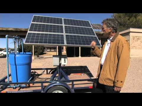
Solar pump inverter sizing starts with the required water volume and pumping head, then checks the motor current, inverter output capability and photovoltaic input limits. Matching the motor’s kilowatt label alone is insufficient. A correctly sized inverter must operate the chosen motor safely while the complete array-and-pump system delivers the required water under the design solar conditions. Treat any fixed panel-to-motor power ratio as a preliminary estimate, not a universal rule. The final selection needs a pump curve, site solar assessment, motor nameplate and the exact inverter’s electrical limits.
Record daily water demand in cubic metres, the required delivery pressure and the seasonal period when the demand must be met. Distinguish an average day from the critical design month. Irrigation, livestock supply and tank filling can have different demand patterns even at the same daily volume. An available borehole yield may impose a separate limit that a larger inverter cannot overcome.
Use the pumping water level rather than only the resting water level. Add the elevation to the delivery point, required pressure head and losses in the pipework at the intended flow. This gives the total dynamic head used to review the pump curve. Pipe length, diameter, fittings and changing well levels can make a system selected from vertical elevation alone inadequate.
The Virginia Tech solar pumping guide sets out water-demand and head assessment as part of system selection. Apply the method to the actual site: a small livestock example is not a rating rule for every industrial three-phase pump installation.
The inverter must supply the motor’s required operating current at the conditions of use. The solar array must also provide enough usable energy across the day. These are related but different checks. A motor may run successfully around noon while the daily water volume remains insufficient because early and late production is too low. Conversely, a large array can still exceed the inverter’s permitted input voltage or current.
For an illustrative hydraulic calculation, useful water energy is E = ρgVH / 3,600,000 in kWh, where water density ρ is approximately 1,000 kg/m³, gravitational acceleration g is 9.81 m/s², V is daily volume in m³ and H is total head in metres. Delivering 50 m³ through 40 m requires about 5.45 kWh of hydraulic energy. This is an example, not a recommended system size.
If the combined motor-and-pump efficiency were assumed to be 50%, that example would require approximately 10.9 kWh at the motor input before other losses. The assumed efficiency must be replaced by suitable performance data. Pumping at variable speed changes the operating point, so a detailed simulation is preferable to dividing the energy by a single assumed number of sunshine hours.
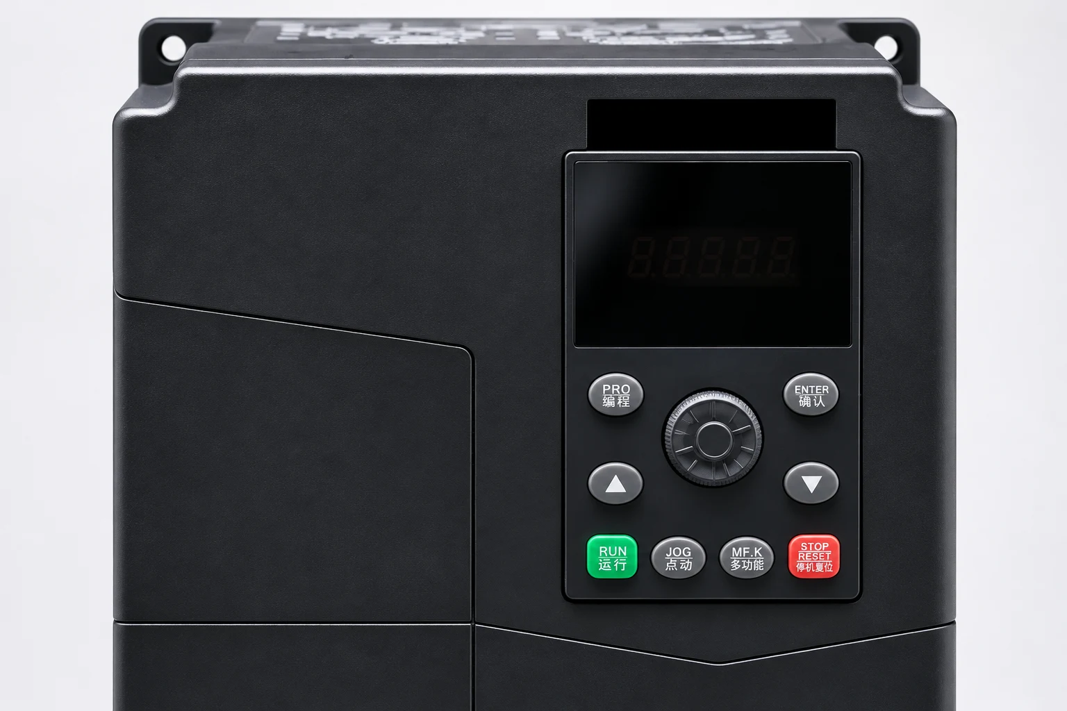
Obtain a clear motor nameplate and confirm rated voltage, phase, current, frequency, power and connection arrangement. Verify that the motor type is supported by the exact inverter model. An induction-motor drive and a permanent-magnet motor controller are not interchangeable merely because their power labels match. Include pump and motor manufacturer requirements for minimum operating speed and cooling.
Compare the motor’s required current with the inverter’s permitted output current after applying the manufacturer’s relevant derating. Enclosure temperature, altitude and installation arrangement may affect the usable rating. Long motor cables can require additional measures that must be reviewed with both motor and drive suppliers. Our temperature and altitude derating guide explains the general review; use the NH133 documentation for the actual selection.
Confirm the pump can deliver against the required head throughout the intended operating range. A drive that starts a motor smoothly cannot guarantee useful flow at low solar input. At some conditions, the available speed may not produce enough head to move water to the delivery point. Define sleep, restart and dry-running behaviour using verified controller capabilities rather than assuming that every solar inverter provides the same functions.
The array’s cold-weather open-circuit voltage must remain within the inverter’s maximum permitted DC input. Its operating voltage under hot conditions must also suit the operating or MPPT window. Use module temperature coefficients and a site-appropriate temperature assessment. A series string that appears acceptable from standard-test-condition values can be unsuitable at a temperature extreme.
Parallel strings raise available current. Check the manufacturer’s limits for operating input current and allowable short-circuit current, along with the required protection and isolation arrangement. Do not infer an approved array size from a single maximum-voltage value. Ask the supplier to review the proposed module datasheet and series/parallel arrangement in writing.
MPPT describes tracking an electrical operating point; it does not increase the available sunlight or remove water-side constraints. Shading, soiling and high module temperature can reduce useful output. Seasonal solar availability should therefore be considered alongside seasonal water demand. Where water storage is practical, a tank can separate daytime pumping from the timing of consumption.
| Input | Evidence to collect | Decision supported |
|---|---|---|
| Daily water volume | Demand schedule for the critical season | Required daily pumping output and storage |
| Total dynamic head | Pumping water level, delivery pressure and pipe-loss calculation | Pump curve and useful speed range |
| Motor duty | Nameplate and motor/pump operating limits | Output voltage, current and motor compatibility |
| PV array | Module datasheet, string layout and temperature assumptions | DC voltage and current compliance |
| Solar availability | Site-specific seasonal resource and shading assessment | Daily water feasibility |
| Site conditions | Temperature, altitude, enclosure and cable route | Derating, protection and installation requirements |
The New Mexico State University design-spreadsheet manual offers a useful example of documenting assumptions and comparing water-pumping inputs. The checklist above is a procurement framework; it is not a substitute for the final electrical and hydraulic design.
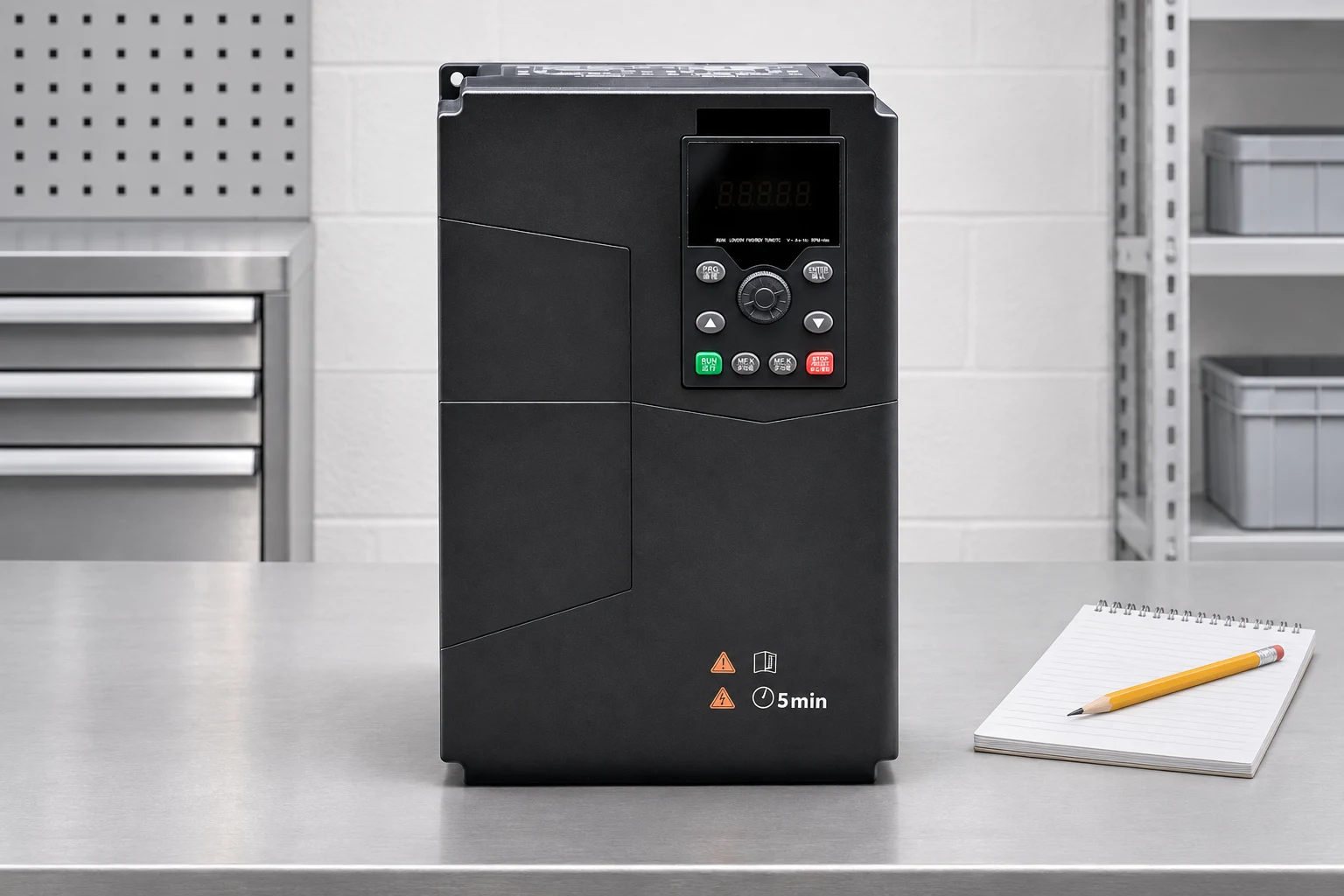
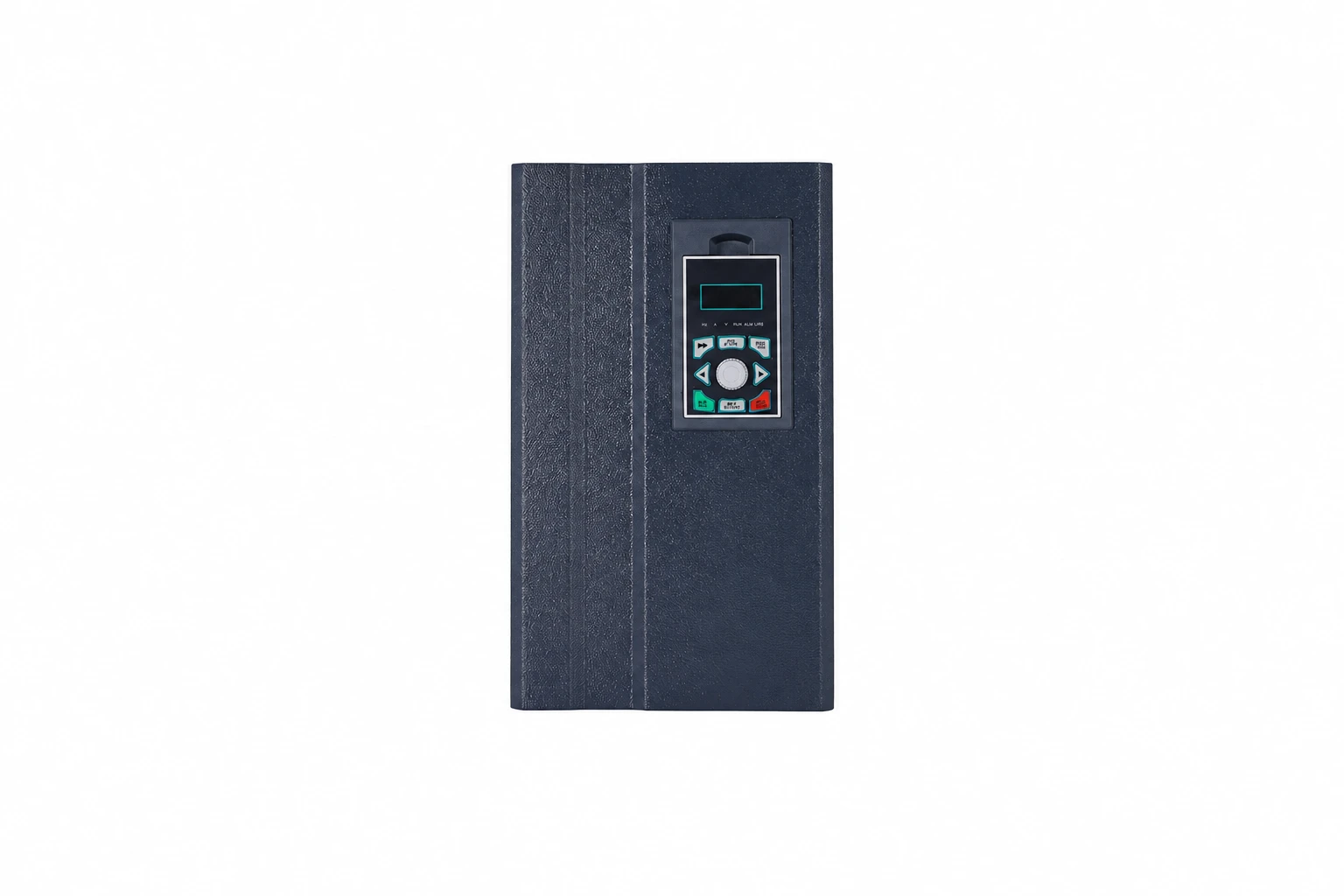
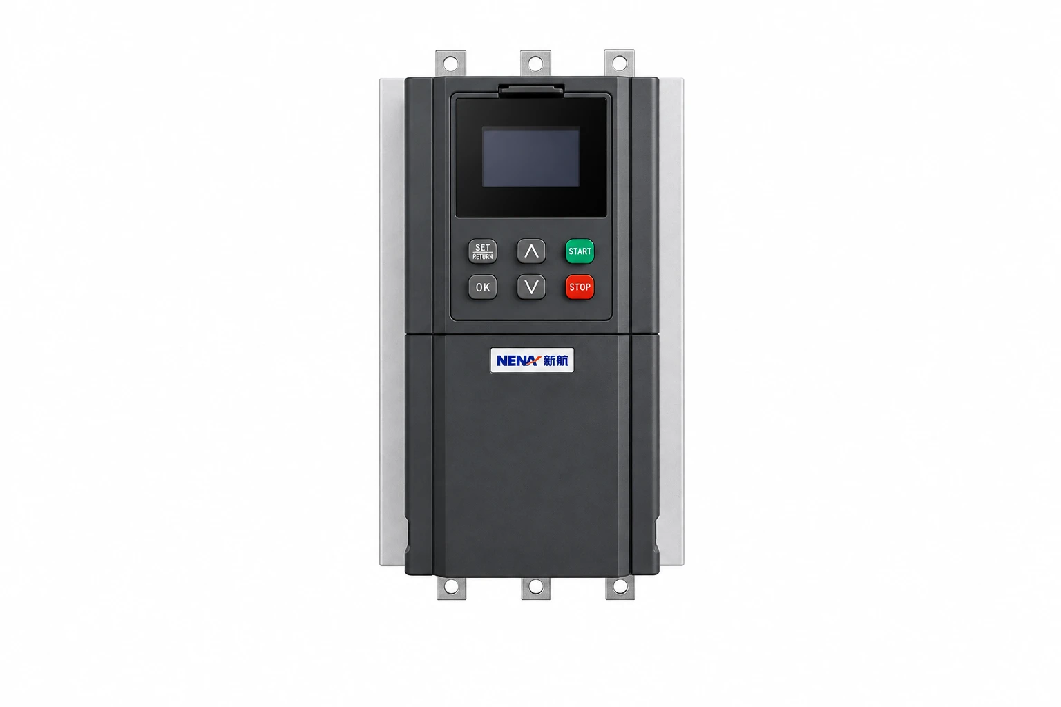
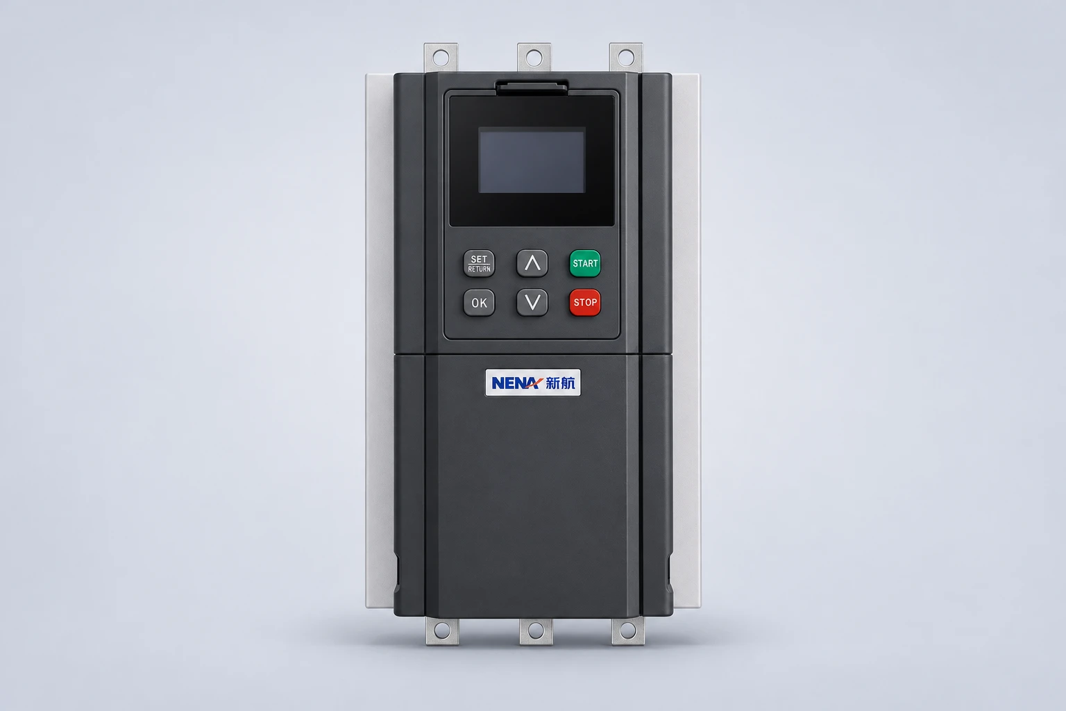
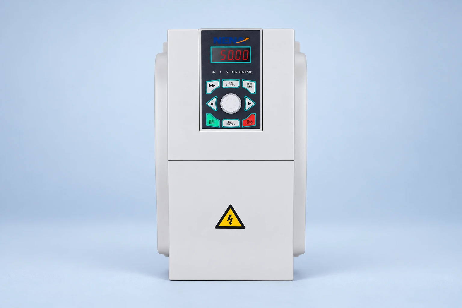
NENA’s NH133 solar water pump inverter is a relevant product family to include in an enquiry. The reference-based photographs identify that product’s visible enclosure and keypad. They do not establish its input window, protection functions, environmental rating or compatibility with a particular pump. Obtain the current manual and model-specific data before placing the order.
For background on the pump-and-drive relationship, read the VFD pump selection guide. Installation handover should also address motor output cable and shielding requirements. These related subjects support the project but do not replace this article’s main task: matching water demand, inverter capability and solar input.
Identify who supplies DC isolators, protective devices, surge protection, sensors, enclosure and commissioning. If grid or generator support is required, confirm that the selected model supports the intended arrangement and obtain an approved changeover design. Do not connect unlike power sources together based on a product-family description or an assumed “hybrid” feature.
Record the accepted parameter set, array configuration, motor information and controller version. During planned testing, measure flow, pumping head and relevant electrical operating values under known conditions. Compare those results with the design prediction for the available sunlight. A successful run command proves much less than a documented water-delivery test.
Test the agreed low-water, tank-full and restart sequences using safe procedures. Confirm that loss of a sensor or restoration of power produces the intended response. Record alarms and the responsibilities for periodic inspection. A clear handover allows later changes in well level or water demand to be distinguished from a controller fault.
A buyer may already own a three-phase pump and ask for an inverter with the same kilowatt rating. First confirm the pump curve and motor nameplate, then check the required water output at the site’s head. If the existing pump operates poorly at reduced speed, a larger PV array alone may not make the daily operating pattern satisfactory. Compare the complete system prediction with an alternative pump selection.
Keep assumptions visible in the offer: the pumping water level, seasonal resource, module arrangement and any permitted shortfall. If a supplier’s calculation uses an average annual sunny day while the requirement applies to the least sunny month, the two documents answer different questions. Resolve that difference before treating the proposed inverter rating as a completed design.
The university video below introduces solar-powered water pumping and its principal components. Use it to understand the whole system before reviewing a supplier’s calculation; the exact electrical design still depends on the selected equipment.
No. Check motor current and voltage, supported motor type, output derating, array voltage and current, and whether the complete system can meet the daily water duty.
There is no universal ratio. Seasonal irradiance, module temperature, hydraulic duty, losses and the inverter’s permitted DC input all affect the acceptable array size.
No. Some systems pump during daylight and store water for later use. Whether that is suitable depends on demand, storage capacity, water quality and the required supply reliability.
Send daily water demand, total dynamic head, pump curve, motor nameplate, site location, solar module datasheet, proposed strings, cable lengths and any backup-power requirement.