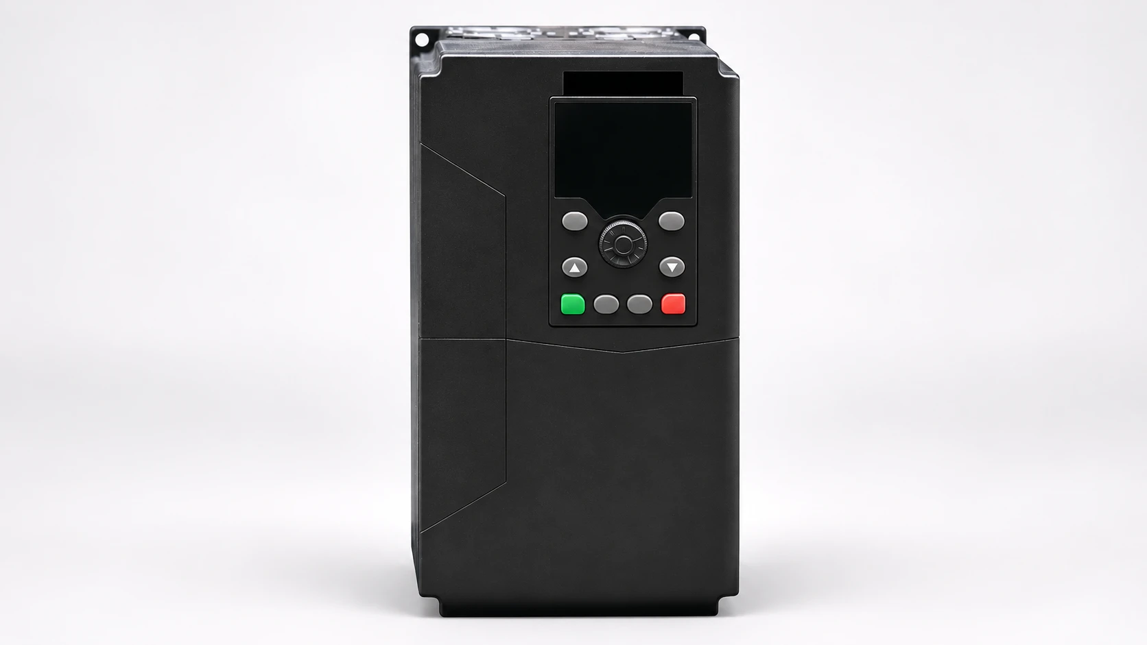
A power meter negative power reading can indicate genuine export, reversed current-sensing polarity, incorrect phase assignment or a measurement configuration problem. Do not reverse wires merely to make the display positive. First establish the meter’s sign convention, the measurement point and whether power can physically flow back toward the source. Then compare the individual phase readings with the approved wiring and operating state. For a current-transformer-fed installation, investigation must also protect the CT secondary circuit. This guide explains how to organize a diagnosis without treating a positive total as proof of correct metering.
A meter needs a reference direction. Imported power may be displayed as positive in one system, while a supervisory screen may use a different convention. Establish the convention from the exact meter manual and the configured data point. Record whether the complaint concerns the local display, a communications register, an energy total or a calculated dashboard value.
Mark the measurement point on the single-line drawing. A meter at a building incomer observes a different boundary from one at a solar inverter or a motor feeder. If generation is connected inside the measured boundary, export may be a real operating condition. If the drawing and the dashboard use different boundaries, the readings can appear contradictory without either device being defective.
El U.S. Bureau of Reclamation protective relay maintenance reference explains instrument-transformer testing and polarity in its own application context. Use those principles with the actual metering documentation; a relay maintenance procedure is not automatically the procedure for a particular compact meter.
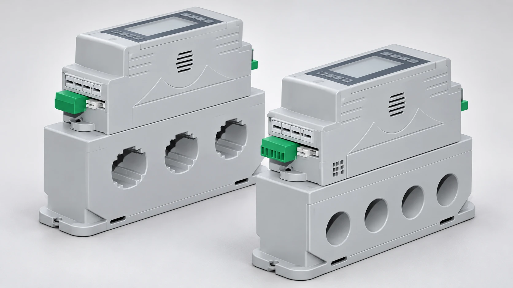
A total can hide opposing errors. One phase may register negative power while others register positive, leaving a plausible-looking aggregate. Record each available phase voltage, current, active power and power factor at the same time. Note the load and any generation operating during that observation. Avoid combining readings taken while the process was changing.
An unexpected sign on one phase suggests a different investigation from a sign reversal on all phases. It does not establish the cause on its own. Check the association between each voltage input and current channel, the defined current direction and the configured system type. A phase-labeling error can survive a superficial check that every conductor is connected.
A known operating condition helps establish an expectation. The responsible engineer can choose a suitable authorized condition and compare the meter with an appropriate reference. Do not create a test by defeating generation protection, switching unidentified conductors or opening equipment without an approved method. The goal is a controlled comparison, not a trial-and-error search for a positive number.
| Patrón observado | Check first | Do not conclude yet |
|---|---|---|
| Negative total during solar generation | Measurement boundary, sign convention and generation versus demand | That every negative reading is a wiring fault |
| One phase negative during expected import | That phase’s voltage-current pairing and sensing direction | That the meter itself has failed |
| All phases negative after installation | Common direction convention and approved connection diagram | That reversing all inputs is automatically correct |
| Local display differs from dashboard | Register identity, data type, scaling and timestamp | That physical rewiring is necessary |
| Plausible total but unusual phase values | Individual channels under a defined operating condition | That a positive total proves correct phase assignment |
This table organizes hypotheses. The polarity and circuit-control basis comes from the Bureau of Reclamation reference and IOGP S-560. Neither document assigns a universal sign convention to all meters or verifies this website’s pictured meter configuration.
For a CT-fed meter, the primary orientation and secondary terminal relationship determine the current signal’s defined direction. The CT markings and the meter’s connection diagram must be interpreted together. Do not identify polarity from insulation color alone; installations and supplied devices can use different markings and conventions.
Phase assignment asks a different question: does the current channel belong with the voltage channel used in the power calculation? A correctly oriented sensor can still be assigned to the wrong phase. Label the relationship end to end on the approved drawing and verify it through the authorized commissioning method. Correcting only the sign can leave the phase association unresolved.
Maintain a record of the original observations before a correction. Record exactly what changed and why. If several changes are made simultaneously, the final result may improve without showing which cause was responsible. A staged, documented investigation is easier to review and gives the next engineer useful evidence if the symptom returns.
A traditional CT secondary circuit needs appropriate precautions and must not be opened casually while the primary carries current. A voltage-output sensor, a Rogowski system and a direct-current-path meter are different arrangements with different instructions. Identify the actual technology before selecting a test or service method. Do not apply a CT shorting procedure to an unidentified sensor.
IOGP S-560 includes provisions for CT secondary circuits in its specified assemblies. This supports the need to treat the circuit deliberately, but it does not supply a universal retrofit scheme. Ask the designer to identify the approved test or shorting facilities where applicable, and follow the equipment-specific procedure with qualified personnel.
Never swap secondary leads live to see whether the sign changes. The meter display is not an adequate basis for choosing a safe work method. If the installed circuit lacks documentation or suitable facilities for the planned work, resolve that issue before proceeding. An unclear metering drawing is a documentation defect, not permission to improvise.
cURL Too many subrequests by single Worker invocation. To configure this limit, refer to https://developers.cloudflare.com/workers/wrangler/configuration/#limits.
cURL Too many subrequests by single Worker invocation. To configure this limit, refer to https://developers.cloudflare.com/workers/wrangler/configuration/#limits.
cURL Too many subrequests by single Worker invocation. To configure this limit, refer to https://developers.cloudflare.com/workers/wrangler/configuration/#limits.
cURL Too many subrequests by single Worker invocation. To configure this limit, refer to https://developers.cloudflare.com/workers/wrangler/configuration/#limits.
cURL Too many subrequests by single Worker invocation. To configure this limit, refer to https://developers.cloudflare.com/workers/wrangler/configuration/#limits.
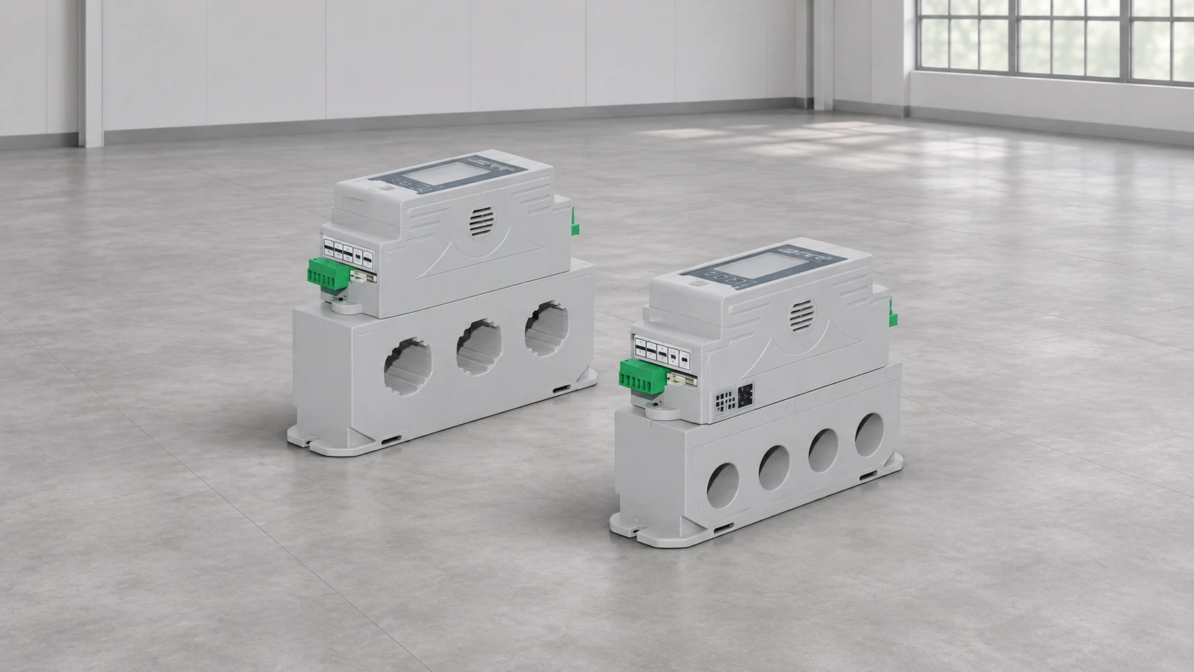
cURL Too many subrequests by single Worker invocation. To configure this limit, refer to https://developers.cloudflare.com/workers/wrangler/configuration/#limits integrated power meter. Ask for the exact model manual, sensing arrangement, connection diagram, sign convention and communications map. The reference photograph shows aperture-style devices; it does not establish that the pictured version accepts external CTs, supports bidirectional energy totals or offers software polarity correction.
For the broader installation context, see the guía de selección de armarios de control de motores. When measurements are being used to justify compensation changes, read the power factor correction sizing article and resolve metering uncertainty first. The capacitor bank hunting guide covers a separate control symptom that should not be diagnosed from one unexplained meter value.
After an approved correction, repeat the defined observation and compare local and remote values for the same quantity and time. Record the final phase association, direction convention and relevant settings. Keep the original readings as evidence of the problem rather than overwriting them with the corrected values.
Where meter data feed an energy report or control system, identify the period affected by the error. Have the responsible team decide how historical data should be treated. Correcting the current display does not automatically repair previous records, and estimated replacements should remain clearly distinguished from measurements.
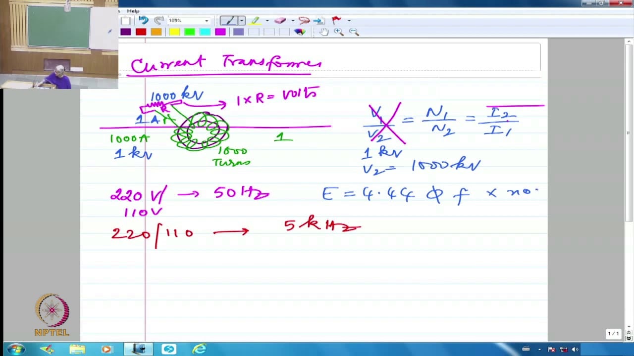
The NPTEL lecture below introduces instrument transformers and their measurement role. It provides academic context, not a live testing procedure or a connection diagram for the pictured meter.
Ver en YouTube — NPTEL IIT Delhi
No. Genuine export, sign conventions, phase assignment and data mapping also need consideration.
No. Correct power interpretation also depends on the voltage-current relationship, direction and configuration.
No. Use the qualified equipment-specific service procedure and the required precautions for the actual sensing technology.
Record the measurement boundary, operating state, sign convention, each available phase value, relevant settings and the approved drawing revision.