A power meter CT ratio tells a compatible meter how primary current relates to the current supplied by its external current transformers. An incorrect ratio can make current, power and energy values consistently too high or too low. Before changing it, identify the actual sensing arrangement, read the installed CT ratings and establish whether the meter already reports primary values. Then trace every multiplier through the display, communications gateway and reporting software. Applying the same factor twice can create an error even when the meter itself is correctly configured.
This guide covers conventional external-CT metering and its data chain. It does not assume that an integrated sensor meter accepts external CTs or exposes a user-adjustable ratio. Hardware compatibility and safe working methods must be confirmed for the actual installation.
Begin with the meter model, wiring diagram and sensor documentation. Distinguish a direct-connected meter, a meter with integrated current sensing and a meter designed for external CT inputs. Similar-looking displays do not establish interchangeable inputs. A conventional current-output CT, a low-voltage-output sensor and a flexible sensing coil require the correct compatible interface.
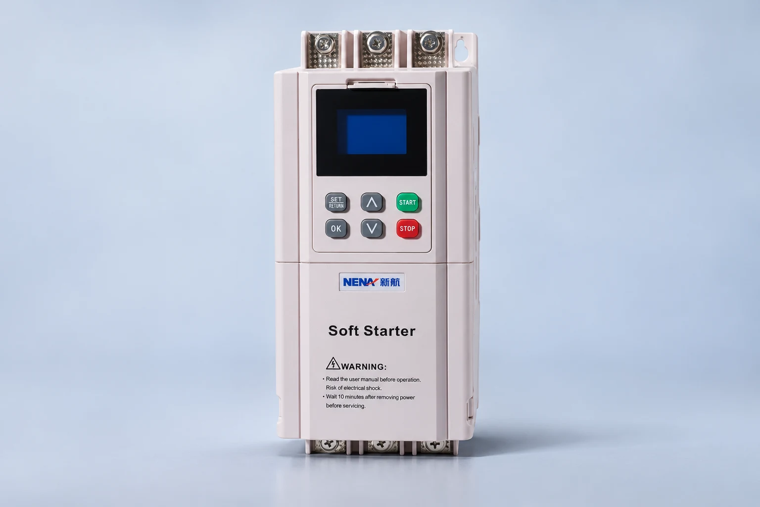
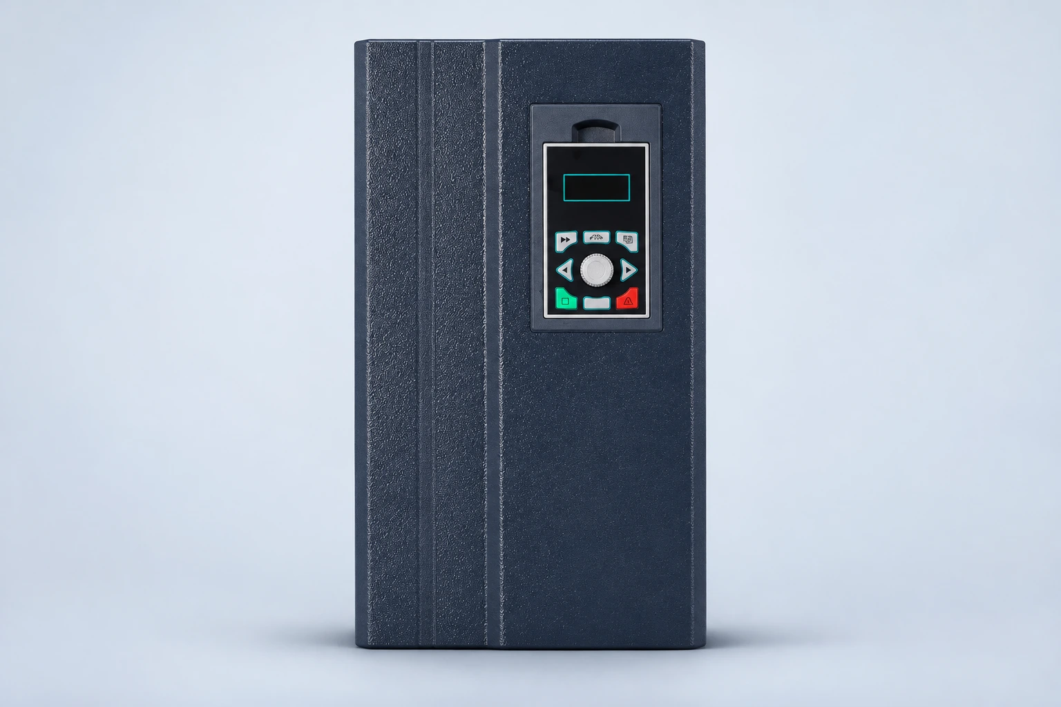
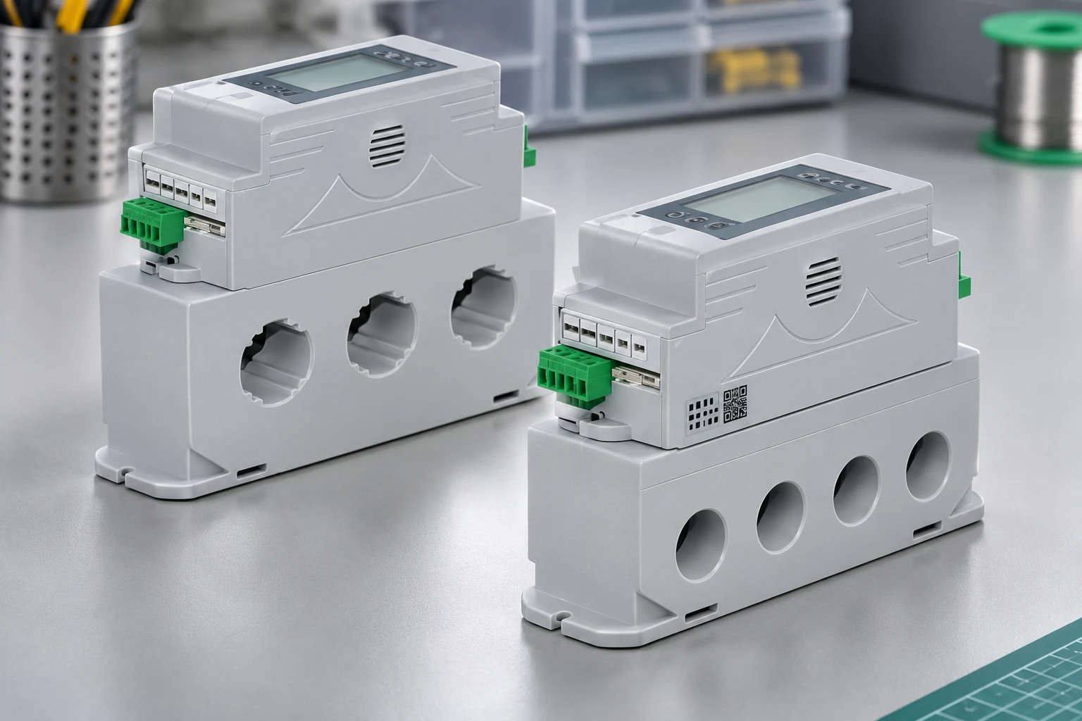
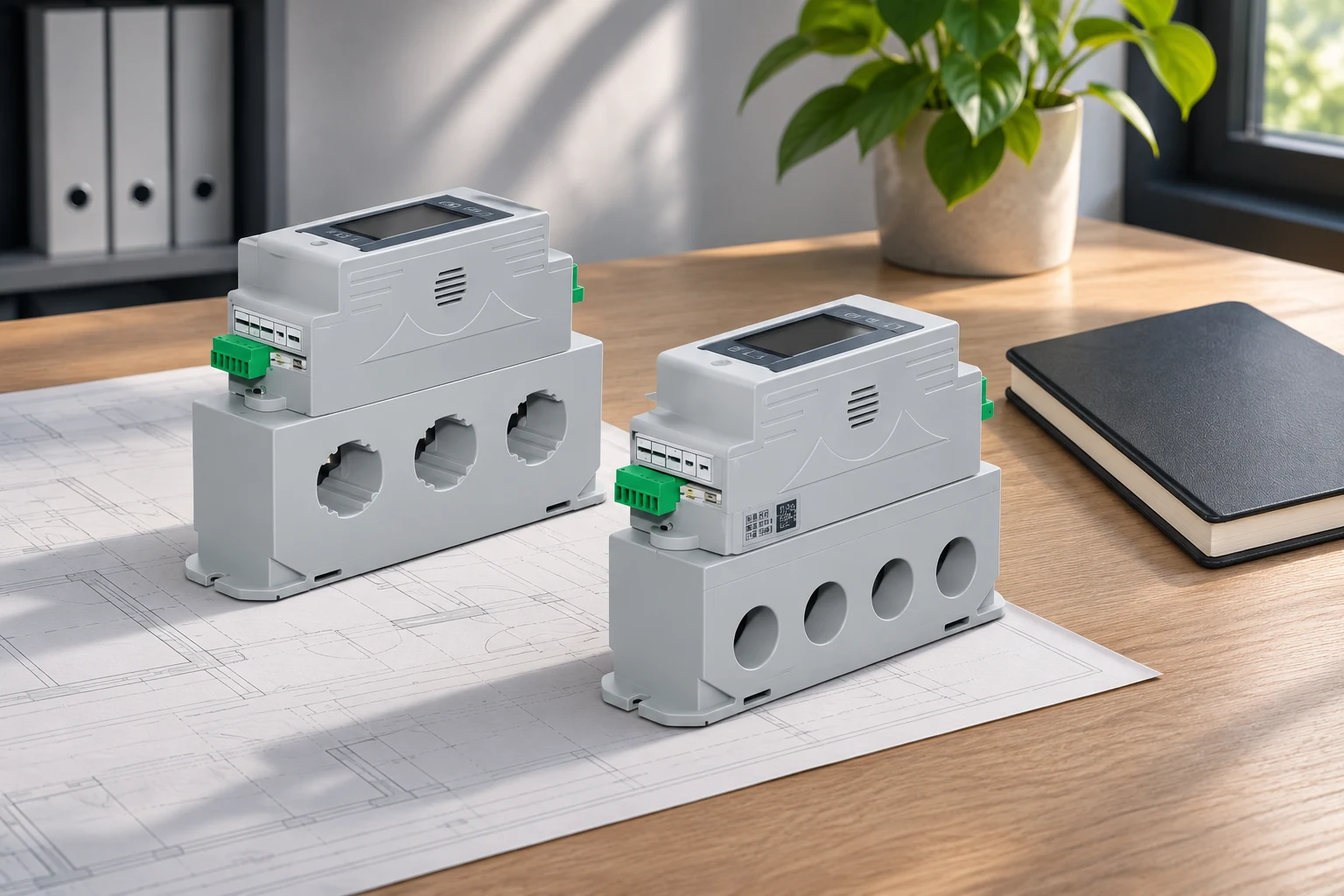
O NENA integrated power meter provides the real product reference for this article’s illustrations. The visible conductor apertures and integrated housing do not prove support for external 1 A or 5 A CTs. Ask for the actual input specification, wiring diagram and configuration manual before proposing this product for an external-CT application.
For the wider procurement scope, review the digital measuring instrument range. Specify the measurement requirement before selecting the enclosure format. A physically convenient instrument can still be unsuitable for the installed sensors, measurement boundary or communications requirements.
For a conventional CT identified as 400:5 A, the nominal ratio is 400 divided by 5, or 80. At the rated primary current, the nominal secondary current is 5 A. The ratio is a relationship between two currents; it is not an instruction to enter the number 80 into every meter. Some instruments request separate primary and secondary settings, while others use a factor or an application-specific configuration.
PNNL’s electricity metering guidance explains the role of current transformers in reducing current to a measurable level. Read that principle alongside the instrument manual. Input type, rated secondary current and permitted sensor arrangement must agree before a numerical ratio is meaningful.
Record the installed CT nameplate for each phase and the actual selected tap where relevant. Do not rely exclusively on an old drawing if a sensor has been replaced. If the rating is inaccessible or illegible, arrange an authorized verification rather than estimating from conductor size.
Consider an illustrative conventional installation with 400:5 A CTs, no voltage transformer and no additional register constant. Assume the recorded value is explicitly on the secondary basis and no internal or software scaling has been applied. The current factor is 80, so a secondary-register energy increment of 2 kWh corresponds to 160 kWh on the primary basis.
The arithmetic is 400 A ÷ 5 A = 80, followed by 2 kWh × 80 = 160 kWh. The factor is dimensionless; the energy unit remains kWh. These numbers are a teaching example, not a product rating, a test result or a consumption estimate for a NENA device.
If the meter already reports primary energy, that reported 160 kWh must not be multiplied by 80 again. If voltage transformers or another approved register constant are present, the conversion basis changes. The City of Banning’s multiplier explanation distinguishes current-transformer factors from combined current-and-voltage-transformer factors.
Draw a simple record of the measurement chain: sensor, meter, communications register, gateway and final report. For each stage, identify the incoming unit, the outgoing unit and any multiplication applied. Record whether the register is expressed in Wh or kWh and whether the number is a primary or secondary value.
A gateway may correctly read a register and still apply an inappropriate multiplier. A reporting system may correctly store a number but attach the wrong engineering unit. Neither situation is solved by changing the installed CT ratio. Compare local and remote values at the same timestamp before deciding where the error originates.
Retain the register definition and the software mapping used for the comparison. A screenshot showing “energy” without its unit or register basis is insufficient. Ask the integrator to identify the exact point rather than adjusting a dashboard factor until the result looks plausible.
This qualitative table organizes the review. It does not provide an accuracy tolerance or authorize live testing. Acceptance limits must come from the applicable project specification, instrument documentation and approved test plan.
| Check | Evidence | Error it helps separate |
|---|---|---|
| Installed sensor identity | CT rating, output type, selected tap and phase label | Wrong hardware or undocumented replacement |
| Meter configuration | Primary and secondary settings or documented factor | Correct sensor with incorrect configured ratio |
| Local measurement basis | Display unit and primary-versus-secondary convention | Missing conversion or a factor applied twice |
| Remote mapping | Register definition, gateway scaling and software unit | cURL Too many subrequests by single Worker invocation. To configure this limit, refer to https://developers.cloudflare.com/workers/wrangler/configuration/#limits |
| cURL Too many subrequests by single Worker invocation. To configure this limit, refer to https://developers.cloudflare.com/workers/wrangler/configuration/#limits | cURL Too many subrequests by single Worker invocation. To configure this limit, refer to https://developers.cloudflare.com/workers/wrangler/configuration/#limits | cURL Too many subrequests by single Worker invocation. To configure this limit, refer to https://developers.cloudflare.com/workers/wrangler/configuration/#limits |
cURL Too many subrequests by single Worker invocation. To configure this limit, refer to https://developers.cloudflare.com/workers/wrangler/configuration/#limits.
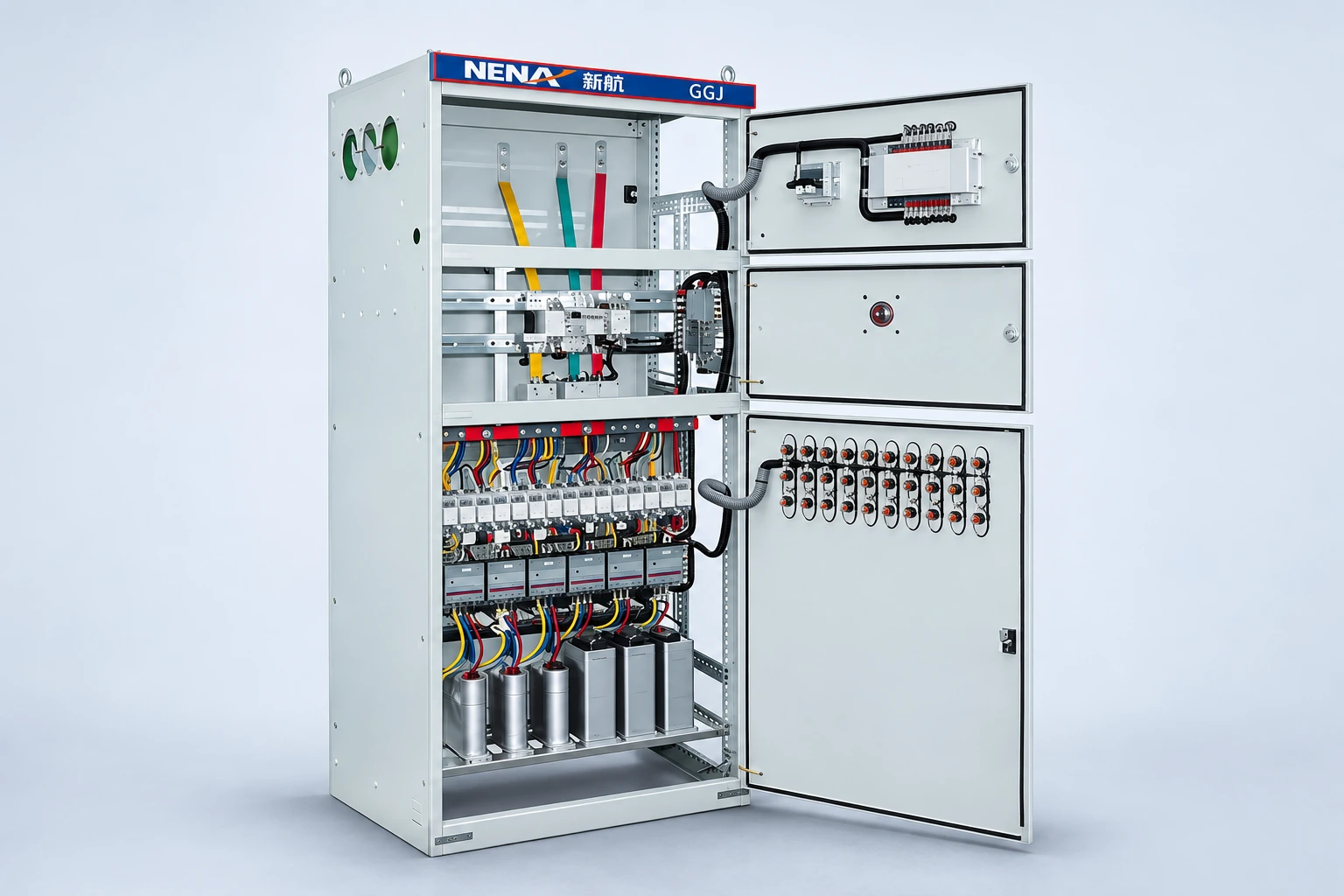
Use o cURL Too many subrequests by single Worker invocation. To configure this limit, refer to https://developers.cloudflare.com/workers/wrangler/configuration/#limits cURL Too many subrequests by single Worker invocation. To configure this limit, refer to https://developers.cloudflare.com/workers/wrangler/configuration/#limits guia de dimensionamento do painel de correção do fator de potência supplies complementary system context. Neither substitutes for validating the meter’s own sensing and data configuration.
Compare corresponding quantities. A current reading cannot be validated simply by matching a power reading to a motor’s nameplate rating. The nameplate is not a simultaneous measurement of actual load. Likewise, an upstream utility total may include loads absent from the submeter boundary.
Plan the comparison with the responsible electrical team. Identify the exact circuit, phase and observation time. Use a reference method appropriate to the installation and document its limitations. Capture the meter display and the relevant software point close enough in time to avoid mistaking a changing load for a scaling discrepancy.
Where readings differ by a consistent factor, compare that factor with the documented ratios and units. Treat the match as a diagnostic clue, not final proof. Multiple configuration mistakes can occasionally offset each other, producing a plausible number in one operating condition while remaining wrong elsewhere.
Do not select an arbitrary pass tolerance from a general article. Consider the instrument and CT accuracy, operating range, reference instrument and test uncertainty. Formal revenue-meter acceptance and facility trend verification have different objectives and may require different authorized procedures.
Access to a configuration screen does not authorize physical work on the metering circuit. Conventional current-output CT secondary circuits can present dangerous voltages if opened while primary current flows. Do not disconnect sensor leads to investigate a reading. Arrange the approved isolation and testing method with qualified personnel.
HSE’s electrical safe-working guidance explains why identification, planning, isolation and suitable competence matter. Local requirements and the equipment owner’s procedures control the work. This article intentionally does not describe a live CT shorting or disconnection procedure.
Software changes also need a defined scope. Preserve the original configuration, identify the authorized replacement values and know how affected reports will be handled. Avoid changing several unrelated settings during the same investigation, because that makes the successful correction difficult to identify and reproduce.
A corrected display does not automatically repair earlier consumption records. Identify the earliest supported start of the configuration error, the correction timestamp and the reporting systems affected. Preserve raw data and record any approved adjustment separately. Do not silently rewrite billing or customer reports based on an unverified assumption about when the error began.
If the factor changed following a CT replacement, retain both sets of hardware records and their effective dates. A single multiplier applied across the whole period may be wrong. Ask the relevant data owner or utility to approve any correction affecting formal reporting or charges.
Send the supplier the one-line diagram, sensing type, current range, intended quantities, phase arrangement and required communications protocol. For an existing installation, include the sensor ratings, meter settings, register definitions and a timestamped comparison. State whether the purpose is monitoring, cost allocation or regulated revenue metering.
Request confirmation of compatibility and documentation for the exact supplied model. Do not assume that an integrated meter and an external-CT meter share interchangeable settings. This question should be resolved before purchase, rather than after installation when a reading appears incorrect.
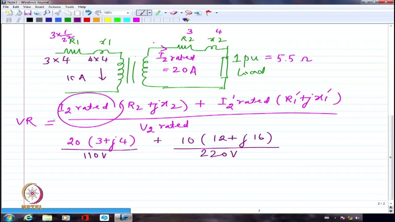
NPTEL IIT Delhi’s introductory instrument-transformer lecture provides background for understanding how measured quantities are transformed. It supports the ratio concept and is independent educational material, not a setup tutorial for the product pictured here.
Assista no YouTube — NPTEL IIT Delhi
Its nominal primary-to-secondary current factor is 80. The required meter entries depend on whether the instrument requests primary and secondary currents separately or uses another documented setting format.
No. Establish the reading basis first. A meter or gateway may already provide primary values, so applying the same ratio again would overstate the result.
Only if the exact model documentation confirms compatible external inputs. Conductor apertures or a similar display do not establish external-CT support.
Not automatically. Historical data requires a separate review of affected dates, original records, scaling stages and authorized corrections by the responsible data owner.