Power meter Modbus communication troubleshooting works best when you separate four questions: is the meter powered, can the serial link carry valid messages, does the meter accept the request, and is the returned value decoded correctly? A blank supervisory screen does not identify which layer failed. Start with a documented, read-only request to one confirmed device, record the exact response, and expand the connection only after that baseline works. This approach prevents a register-mapping problem from becoming an unnecessary wiring change and keeps electrical measurement circuits separate from the communications investigation.
Ask what changed and what still works. A meter that displays local readings but disappears from the monitoring system presents a different problem from an unpowered meter. A gateway that reports a timeout presents a different problem from a valid Modbus exception response. A believable current reading beside an impossible energy total may indicate different register formats, scaling or configuration rather than an unstable physical connection.
Save the meter model, firmware revision, communication option, gateway model and software version. Record when the last successful poll occurred and whether other devices failed at the same time. Keep a copy of the original settings before testing. Do not reset the meter as a first step: a reset can remove the network address, measurement ratios, demand configuration or evidence needed to understand the event.
RS485 describes an electrical interface; it does not prove that a particular meter implements Modbus RTU. Confirm the ordered communication option, supported protocol and register document for the exact revision. A similar-looking model may have a different interface or register map. The Texas Instruments RS485 design guide explains the physical bus, termination and stub considerations; it does not define the application registers of a power meter.
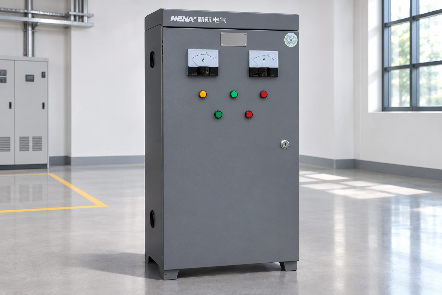
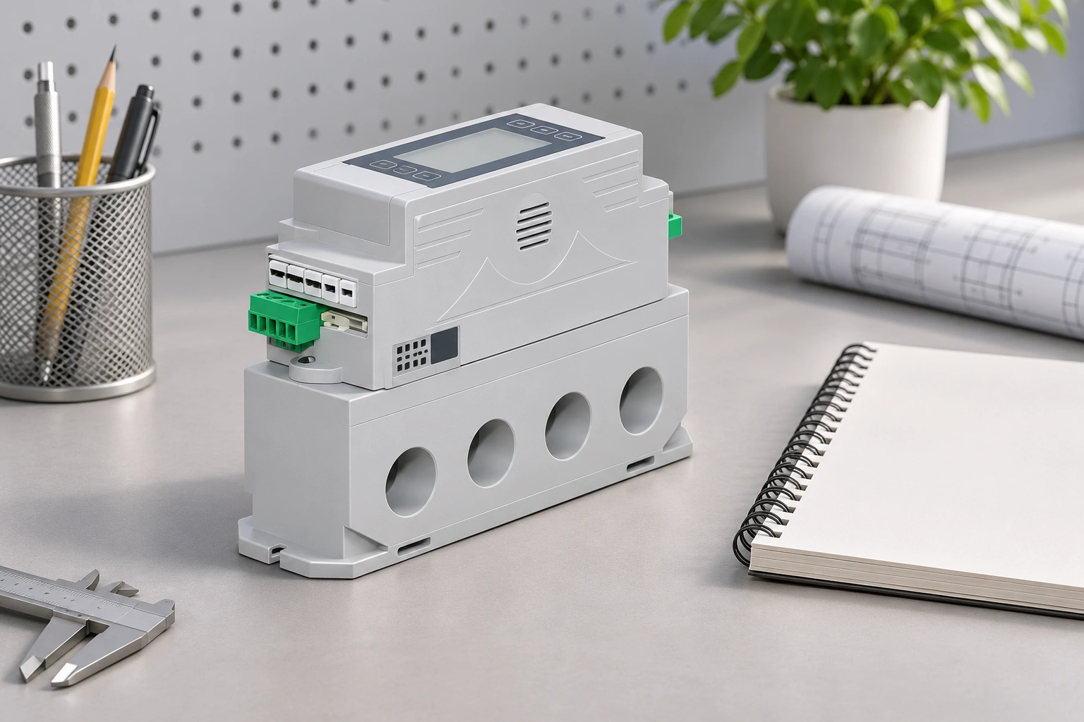
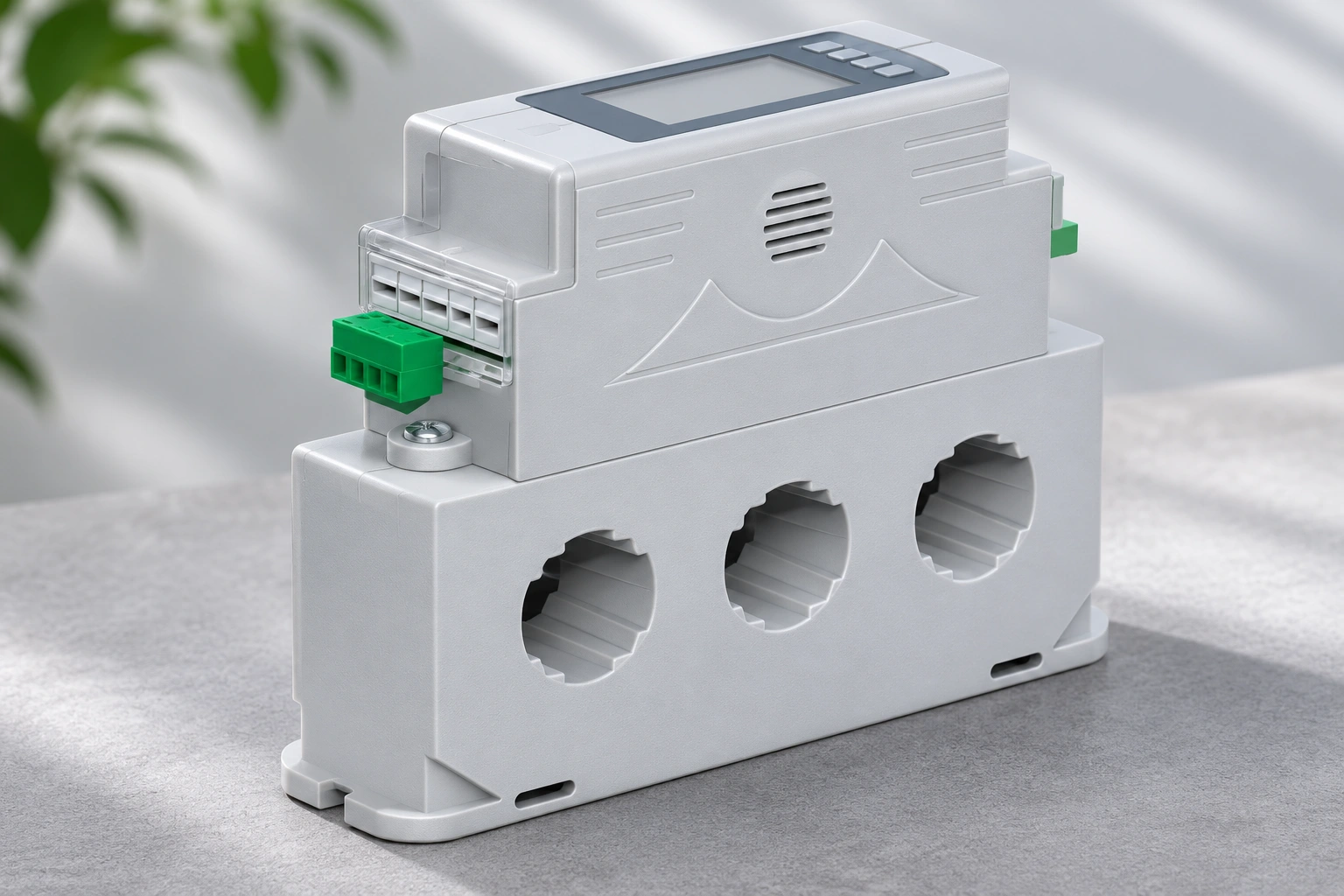
NENA’s integrated power meter product page provides a relevant product reference for a metering project. Confirm the communication implementation and terminal documentation with the supplied device information before specifying it for an existing network. The product photograph illustrates the housing, display and terminal arrangement; it is not a wiring diagram or proof of a particular register set.
A serial connector may be close to hazardous voltage, current transformer circuits or exposed panel equipment. Connecting a laptop is not permission to enter an energized cabinet. Determine whether the required information can be obtained from existing remote diagnostics or a safe external port. Arrange intrusive access under the site’s isolation and work procedures, using personnel competent for the equipment and task.
O HSE guidance on safe electrical working practices covers planning and control of work on or near electrical equipment. Keep voltage and current measurement wiring outside an informal communications experiment. In particular, do not disconnect current transformer secondary wiring to see whether a serial error disappears. Measurement-side faults need their own approved investigation and controls.
The table is a qualitative investigation guide, not a manufacturer fault-code list. Use the device manual and the confirmed network design to decide how each check is performed. The TI physical-layer guidance supports the cabling checks; the exact protocol and register documentation determines the request and decoding checks.
| Observed evidence | Check next | Registo útil |
|---|---|---|
| No local display or status | Confirm the correct supply and device condition through approved access | Supply arrangement, local indication and outage history |
| No response to a known valid request | Device identity, serial settings, selected port and physical path | Request bytes, timeout and selected address |
| Valid exception reply | Function, register range and permitted operation | Exception code and matching register-map revision |
| Intermittent corrupted replies | Bus routing, termination, interference and competing transmitters | Error counts and timestamps against plant operation |
| Stable replies with wrong numbers | Data type, word order, scale and measurement configuration | Raw registers beside the local displayed value |
| Direct connection works, gateway path fails | Gateway routing, unit mapping and serial-side configuration | Working direct request and failing gateway request |
Use one documented measurement with a known register definition and a value visible at the meter. Confirm the device address, baud rate, parity and frame settings at both ends. Do not assume the factory defaults survived commissioning. Check that the computer selected the intended adapter and that another application has not opened the same serial port.
Record the request function, starting address and number of registers. Software may present addresses differently from the manual, including an offset between displayed register references and the transmitted address. Resolve that difference using the software documentation and the register map rather than trying many write operations. A successful read of a documented identification or measurement item establishes a useful baseline.
cURL Too many subrequests by single Worker invocation. To configure this limit, refer to https://developers.cloudflare.com/workers/wrangler/configuration/#limits.
cURL Too many subrequests by single Worker invocation. To configure this limit, refer to https://developers.cloudflare.com/workers/wrangler/configuration/#limits.
cURL Too many subrequests by single Worker invocation. To configure this limit, refer to https://developers.cloudflare.com/workers/wrangler/configuration/#limits.
cURL Too many subrequests by single Worker invocation. To configure this limit, refer to https://developers.cloudflare.com/workers/wrangler/configuration/#limits.
cURL Too many subrequests by single Worker invocation. To configure this limit, refer to https://developers.cloudflare.com/workers/wrangler/configuration/#limits.
cURL Too many subrequests by single Worker invocation. To configure this limit, refer to https://developers.cloudflare.com/workers/wrangler/configuration/#limits guide to demand and instantaneous power. A supervisory system can communicate perfectly while displaying the wrong engineering unit or attaching the wrong label to a valid register.
If values remain consistently offset after decoding is confirmed, review measurement configuration separately. The power meter CT ratio guide addresses one relevant configuration issue. A negative sign also requires investigation of power direction and measurement connections; changing serial polarity will not correct the meaning of a valid negative power value.
When the direct baseline succeeds, follow the data through each additional boundary. Confirm the gateway’s serial port, meter address mapping, network endpoint and supported transaction behavior. A working network connection to a gateway does not prove that its serial-side request reached the meter. Compare the direct request with the software’s actual request, including quantity and address.
Check polling frequency, timeouts and retry behavior against device and network documentation. An overloaded link can accumulate delayed requests and make a healthy meter appear unreliable. Change one variable at a time and observe error counts over a defined interval. Preserve both successful and failed request examples, because an intermittent fault cannot be evaluated from one successful screen refresh.
Record the corrected cause, final settings, register-map revision, raw response and interpreted value. Confirm that ordinary plant operation does not reintroduce timeouts, then restore the full bus and verify all affected devices. Establish how the monitoring system marks stale or unavailable data; a frozen last value should not appear as a fresh measurement.
For a new project, request the communication manual, supported functions, register definitions, data formats, terminal diagram, isolation details and a sample polling configuration before ordering. Include measurement requirements in the same project brief. The guia de seleção do armário de controlo de motores provides a wider context for coordinating monitoring with the equipment and application.
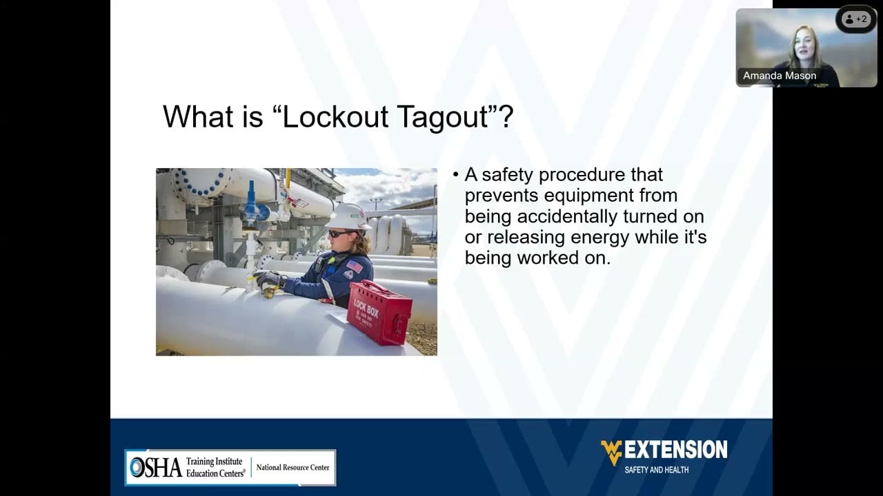
The US Department of Labor video below introduces lockout and tagout principles. It supports the access-planning section rather than teaching Modbus commands; site procedures and task-specific training still determine how the electrical equipment is made safe.
Watch on YouTube — USDepartmentofLabor
No. A timeout can result from the selected port, address, serial settings, wiring, gateway route or request timing. Establish a documented single-device read before attributing the fault to the meter.
Check the register map, address convention, data type, word order, multiplier and engineering units. Compare raw registers with a local displayed quantity before investigating measurement configuration.
No. Termination belongs to the designed bus arrangement and its actual ends. Follow the network and device documentation instead of adding a resistor at each device.
CT wiring is part of the measurement circuit and must not be changed as a communications experiment. Investigate serial transport and measurement configuration as separate tasks under appropriate electrical controls.