VFD motor autotune is a model-specific identification procedure that helps a drive establish parameters for the connected motor. It is different from tuning a pump pressure loop or changing acceleration time. Some identification routines energize a stationary motor; others rotate it and may require the load to be uncoupled. Choose only the procedure supported by the exact drive, motor and application. Before enabling any test, verify the motor data, connection, mechanical condition and safe control of the machine. A successful identification message is a commissioning checkpoint, not proof that the complete machine performs correctly.
A drive’s control method can use an electrical model of the motor to estimate or regulate torque and flux. Identification may establish resistance, inductance or other parameters, depending on the motor type and the manufacturer’s implementation. There is no universal list of values measured by every autotune routine. The selected control mode determines what information is required and whether identification is available or necessary.
Motor identification should be distinguished from speed-loop tuning, inertia estimation and process-loop adjustment. A pressure controller that oscillates may need a review of its sensing, hydraulic system and control gains. Repeating motor identification does not automatically solve that problem. Establish which control layer is under investigation before changing parameters.
For general drive-system context, Natural Resources Canada’s VFD guide discusses the relationship between drives, motors and applications. It is background information; the exact manufacturer’s manual remains the authority for a particular identification procedure.
Collect the motor’s rated voltage, current, frequency, speed and power from the actual nameplate. Confirm the applicable winding connection and the drive’s output voltage capability. A dual-voltage motor may list different currents for different connections. Entering the current associated with the wrong connection can undermine the motor model and the protection settings.
Do not replace the nameplate’s rated speed with calculated synchronous speed. For an induction motor, rated operating speed generally includes slip. Confirm the units expected by the drive, including whether power is entered in kilowatts or horsepower and whether speed is entered directly or inferred through another parameter. Photograph the nameplate and retain it with the parameter record.
Verify the motor type. Induction, permanent-magnet and other motor technologies can require different control selections and identification routines. A procedure for one technology must not be copied to another solely because the keypad menus appear similar. If the plate is incomplete or the motor has been rewound, obtain suitable information before proceeding.
| Routine or task | What to establish before use | What must not be assumed |
|---|---|---|
| Stationary identification | Supported motor/control mode, connection and required motor condition | That a stationary command makes the machine electrically safe |
| Rotating identification | Permitted uncoupling, rotation clearance and the manufacturer’s test requirements | That a coupled production load is acceptable |
| Resistance-only measurement | Exact scope and compatibility with the chosen operating mode | That it identifies every parameter needed for vector operation |
| Inertia or speed-loop tuning | Mechanical configuration, feedback and the drive’s specific procedure | That it is equivalent to electrical motor identification |
| Process PID adjustment | Sensor scaling, process response and control objective | That repeating motor autotune will correct a process-loop problem |
The table identifies questions to ask, not a universal menu sequence. Stationary testing can still energize the motor and produce torque or unexpected movement. Treat the equipment as capable of hazardous action during commissioning. “No intended rotation” and “isolated for work” describe different conditions.
Confirm who controls the run command and speed reference during the test. Local keypad control, remote digital inputs and a supervisory controller may interact. Prevent an unintended remote start using the approved commissioning arrangement. Document which permissives remain active and how the machine will be stopped if conditions become unsafe.
For rotating identification, follow the drive and machine manufacturers’ requirements concerning load removal, brakes and rotation. Uncoupling can itself create mechanical hazards or invalidate a process condition, so it must be planned by competent personnel. Never release a brake or disconnect a driven load based only on a generic online sequence.
Check the final motor cable arrangement and any output contactor, filter or other device with the drive supplier. Identification may depend on the connected circuit, and some output arrangements impose specific restrictions. Do not operate output switching equipment during an active identification routine unless the exact procedure explicitly permits it.
O HSE introduction to electrical safety provides general guidance on competence and specialized work. Use the site’s electrical and mechanical safety arrangements, the equipment instructions and applicable local requirements for the actual commissioning task.
Save an initial parameter backup and record the drive model, firmware, motor identity and selected control mode. Follow the exact manual revision for that equipment. Parameter numbers used by another brand or another series are examples of a different implementation; they are not transferable instructions for a NENA drive.
Confirm the motor’s required initial condition, including whether the procedure specifies a cold or otherwise stabilized motor. Temperature affects electrical resistance, so a routine intended for one thermal state may give a poor result in another. The required condition must come from the manufacturer’s instructions rather than an assumed waiting period.
Record the displayed completion or failure result and the relevant identified values. If the routine fails, retain the message before resetting it. Do not repeatedly change unrelated settings until the fault disappears. Compare the conditions with the manual and investigate the motor data, circuit and mechanical state in an orderly manner.
Begin with the simplest evidence: does the selected motor type match the actual machine, and are the nameplate values correct for its connection? Then check whether the drive’s rating and measurement range suit the motor. A large mismatch between drive and motor requires manufacturer guidance rather than an assumption that extra drive capacity always improves identification.
Have qualified personnel verify connections, cable integrity and the intended output circuit using appropriate isolation and testing procedures. Loose or incomplete connections can invalidate a test. Insulation testing also requires the correct disconnection and protection of electronic equipment; it should never be improvised while a motor remains connected to a drive.
If a rotating routine cannot be performed, ask which alternative is supported and what performance limitations apply. A stationary routine may be useful for some applications, but it is not necessarily equivalent to the complete rotating procedure. Document the approved alternative rather than labeling every incomplete test as a successful tune.
Begin operational verification under the approved test plan. Check direction, stable acceleration, speed response and current at suitable conditions. Compare the driven equipment’s actual behaviour with its design requirement. A normal no-load current does not establish that the machine can start its process load or operate continuously at the minimum intended speed.
For low-speed duty, review motor cooling and required torque separately. The minimum-speed guide explains why the permissible range depends on the motor and application. For the overall control relationship, read como um variador de frequência controla a velocidade do motor. These checks remain necessary even after the identification routine reports completion.
Do not use autotune as a way to conceal a mechanical vibration, unsuitable acceleration rate or braking problem. Investigate the relevant subsystem. Preserve one change at a time in the commissioning record so that improvements and regressions can be traced to a specific action.
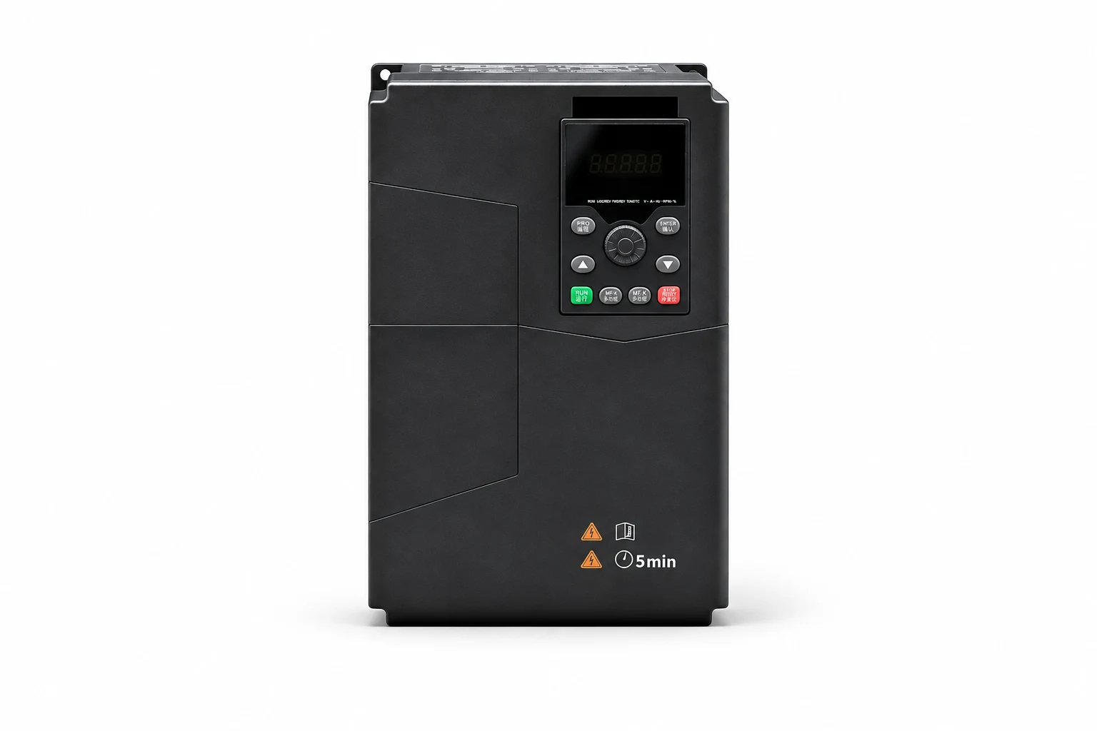
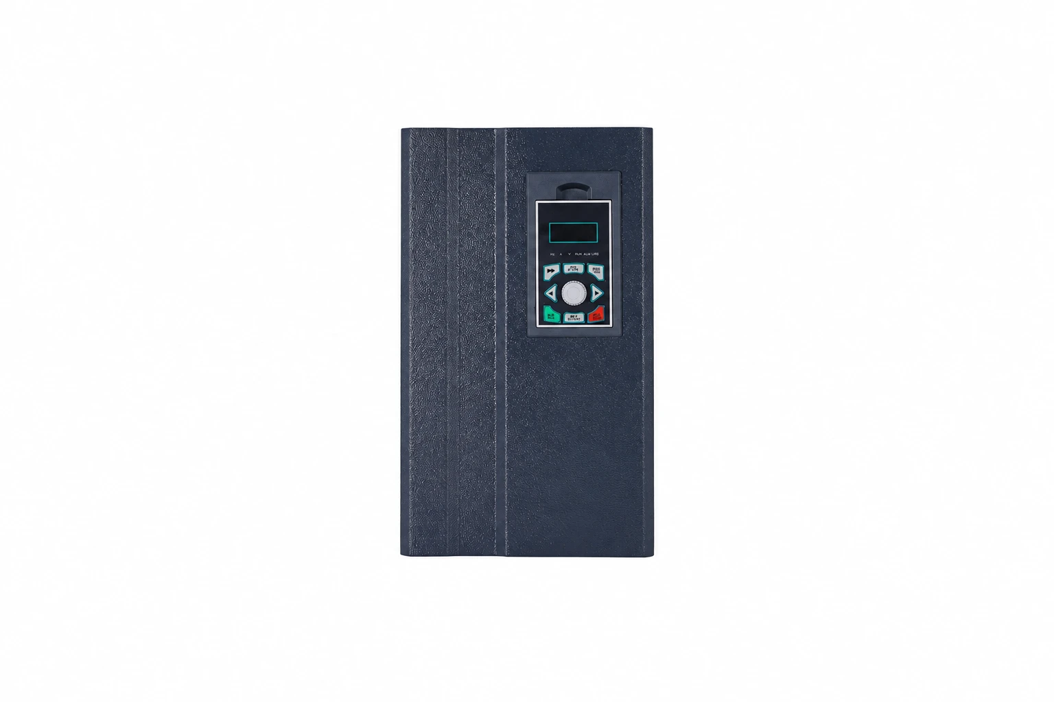
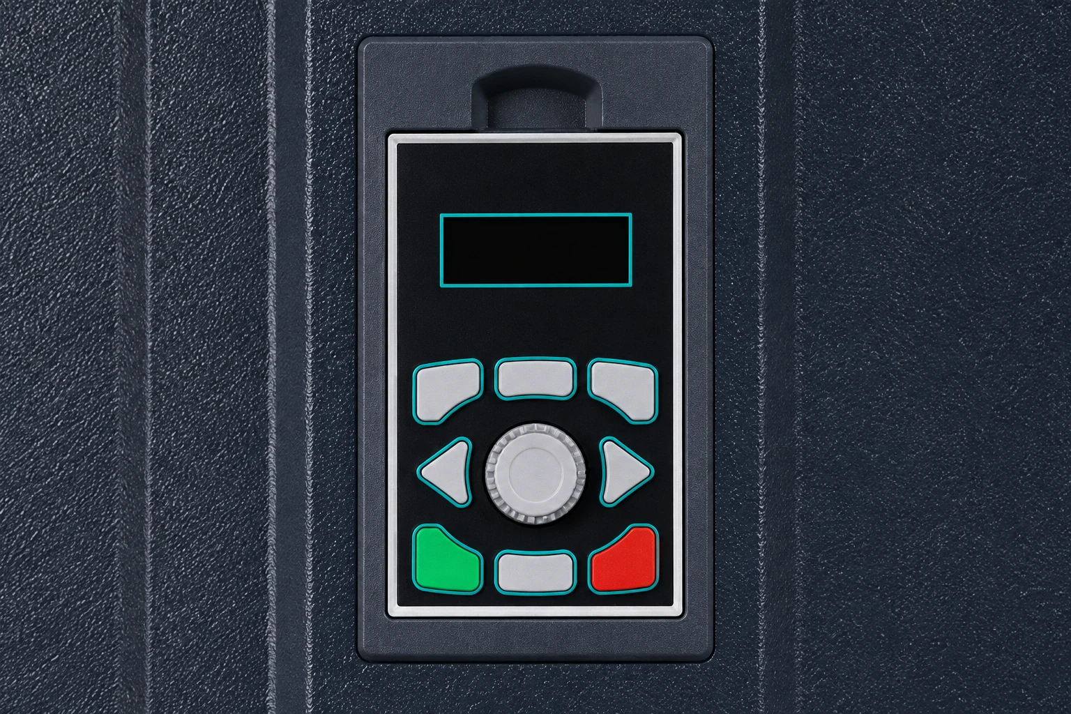
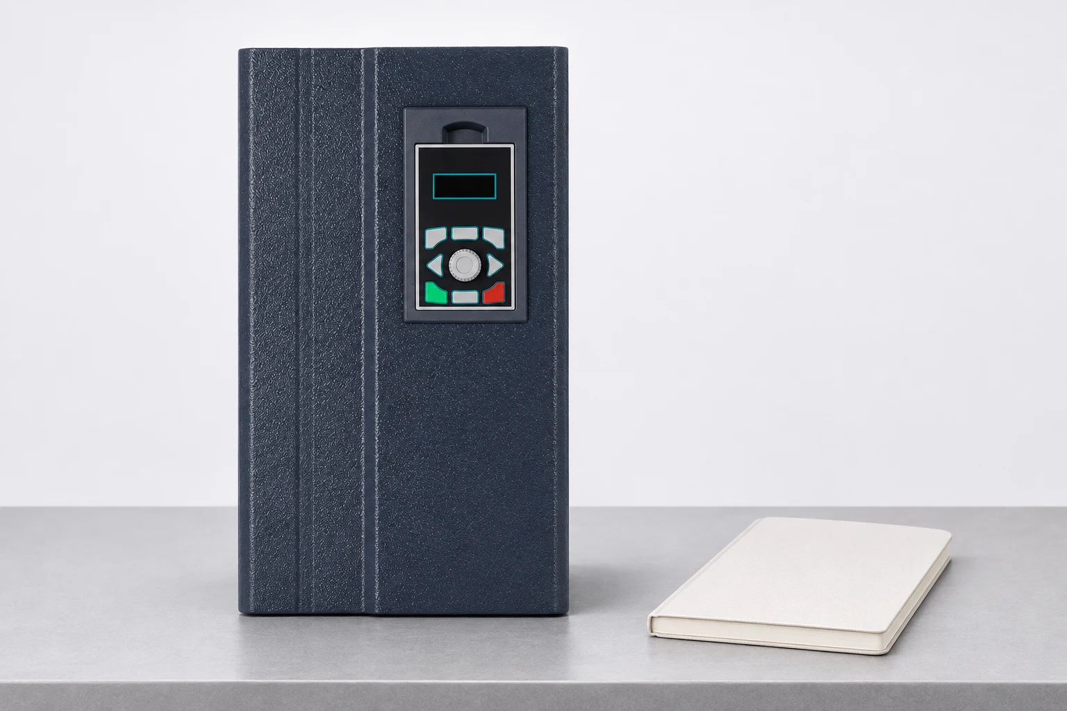
NENA’s 860S current-vector inverter product family is a relevant starting point for an enquiry about vector-control commissioning. The pictured keypad identifies the actual visible product; it does not prove that every model supports the same identification modes. Ask for the exact model manual, supported motor types, routine prerequisites and expected result indicators.
Use the three-phase motor VFD commissioning guide as the upper-level checklist. Provide the motor nameplate, load type, cable length, feedback arrangement and reason for requesting identification support. If a motor or drive is replaced later, review whether the saved parameters and identification data remain applicable before reuse.
The final record should identify which parameters were entered from the nameplate and which values were produced by identification. Save the accepted backup with the drive model, firmware, motor serial number and date. Label any supported alternative routine and its stated limitations. This prevents a later technician from treating an old parameter file as a universal setup for a replacement motor.
Record the operational checks alongside the identification result. A future reviewer should be able to see whether the motor was tested unloaded, coupled or under process load. Those conditions affect what the test actually demonstrates and whether another controlled verification is needed after maintenance.
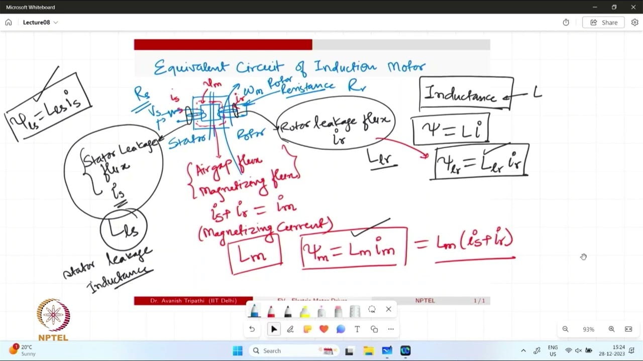
The NPTEL lecture below explains the induction-motor equivalent circuit and torque-speed behaviour. That background makes the purpose of motor identification clearer, while the actual test commands must come from the selected drive’s manual.
Watch on YouTube — NPTEL IIT Delhi
No. The need depends on the control method, application and manufacturer’s requirements. Some operating modes use nameplate data without the same identification process.
Only use the arrangement permitted by the exact manual and the machine’s commissioning plan. Stationary identification can energize the motor and may produce torque.
No. Parameter definitions and test behaviour vary by model and firmware. Use the manual for the exact drive and motor type.
No. Verify direction, acceleration, current, load response, protective functions and the intended operating range before accepting the complete machine.