Power factor correction panel sizing requires measured load data, an agreed target power factor and a review of harmonics and switching duty. The familiar kvar calculation gives an initial reactive-power requirement; it does not select the complete panel. Step sizes, controller measurement, protective devices, capacitor voltage, ventilation and possible detuning still need engineering review. Start with representative site measurements rather than transformer nameplate capacity or a photograph of an existing bank. This guide explains the information a buyer should collect and the checks that make competing quotations comparable.
Real power, measured in kW, performs useful work. Apparent power, measured in kVA, reflects the combination of voltage and current demand. Power factor is their ratio. In a largely sinusoidal system, displacement between voltage and current is a useful part of the explanation. With nonlinear loads, waveform distortion also matters, so true power factor and displacement power factor may differ.
A capacitor bank can offset inductive reactive demand, but a simple bank does not remove every cause of low true power factor. Collect the meter’s definitions and measurement method. Record both displacement and true power factor where available, together with harmonic measurements and load state. Otherwise the project may be sized to correct a number that the proposed equipment cannot adequately address.
Natural Resources Canada’s motor reference guide explains power factor and the risk of overcorrection. Its general principles help frame the enquiry; the target and commercial benefit must come from the site’s tariff and operating conditions.
Log the plant during meaningful production states: normal operation, high output, reduced production and idle periods. Include large intermittent loads and scheduled equipment changes. A single daytime reading may miss the lowest reactive demand, which is essential when evaluating overcorrection. Note any existing capacitor stages that were operating during measurement so they are not counted twice.
Request the measurement location, instrument details and timestamps. Compare the data with the utility’s billing interval and measurement point. A correction panel at one distribution board may reduce current in that feeder while the main service meter sees the combined behaviour of the whole plant. The intended benefit therefore depends on where the bank is connected and controlled.
Check the tariff before making a savings estimate. A reduction in kVA demand or reactive-energy penalties is different from a proportional reduction in kWh consumption. There may also be a reduction in upstream losses, but that requires an appropriate calculation. Do not promise a percentage energy saving merely because the power factor improves from one number to another.
For a balanced sinusoidal example with lagging displacement power factor, the correction estimate is Qc = P × [tan(arccos(PF1)) − tan(arccos(PF2))]. P is the real power in kW, PF1 is the initial displacement power factor and PF2 is the target. The result Qc is in kvar. Both power factors must describe the same relevant operating condition, with values between zero and one.
For example, assume a measured load of 100 kW, an initial displacement power factor of 0.80 and a target of 0.95. The tangent values are approximately 0.750 and 0.329. The preliminary correction is therefore 100 × (0.750 − 0.329), or about 42.1 kvar. This arithmetic is illustrative and does not specify a suitable commercial panel or an appropriate target for a particular utility.
The US Department of Energy motor-systems guide includes power-factor correction in its plant-management discussion. Use the initial result to open the design review, then evaluate the actual load range, harmonic environment and equipment ratings before choosing total kvar and stage arrangement.
A fixed bank may suit a stable reactive demand, while varying demand usually needs staged or otherwise controlled compensation. The smallest stage affects how closely the controller can follow a lightly loaded plant. A large first stage may overshoot the demand at night even when the total bank size suits full production. Compare the minimum and maximum conditions rather than only the peak.
Stage count alone is not enough to compare offers. Ask for the kvar of each stage at the specified voltage and frequency, the permitted switching frequency and the controller strategy. Confirm discharge requirements and the delay before a stage can be reconnected. Fast-changing loads may require a different switching approach from slowly changing production equipment.
Clarify whether the quoted arrangement includes spare stages, installed spare space or only an empty enclosure allowance. These are different supply boundaries. Future compensation should be based on the expected future load and a revised assessment, rather than automatically filling every unused position with capacitors.
VFDs, rectifiers and other nonlinear equipment can introduce harmonic currents. Adding capacitance changes the network’s electrical behaviour and can create an undesirable resonance condition. A low displacement power factor is therefore not sufficient justification for installing an ordinary capacitor bank without reviewing the power-quality environment.
The designer should evaluate the measured distortion, transformer and network impedance, existing capacitors and foreseeable operating configurations. A detuned bank or another compensation approach may be needed, but a reactor percentage cannot be selected safely from a generic blog rule. Ask for the assessment basis and the manufacturer’s permitted capacitor/reactor combination.
Do not place ordinary power-factor capacitors on a VFD’s motor output as a shortcut. The output waveform and the drive manufacturer’s restrictions require a different review from a mains-frequency bus. Coordinate the correction project with the plant’s drive documentation and with the person responsible for the electrical system study.
| Review item | What to request | Problem avoided |
|---|---|---|
| Load profile | kW, kvar and both power-factor definitions across operating states | Sizing from an unrepresentative single reading |
| Stage arrangement | Total kvar and individual stage ratings | Overcorrection during light load |
| Harmonic environment | Measured distortion and network assessment | Unreviewed resonance or capacitor stress |
| Controller sensing | CT location, ratio, polarity and measurement diagram | Incorrect response or repeated switching |
| Thermal design | Ambient assumptions, losses and ventilation arrangement | Overheating in the actual room |
| Protection and discharge | Coordination documents and safe maintenance instructions | Incomplete supply or unsafe assumptions after isolation |
The table is an enquiry checklist, not an installation design. Electrical work and stored-energy precautions require qualified personnel; consult the HSE electrical safety guidance for general competency context and follow the equipment instructions and local requirements.
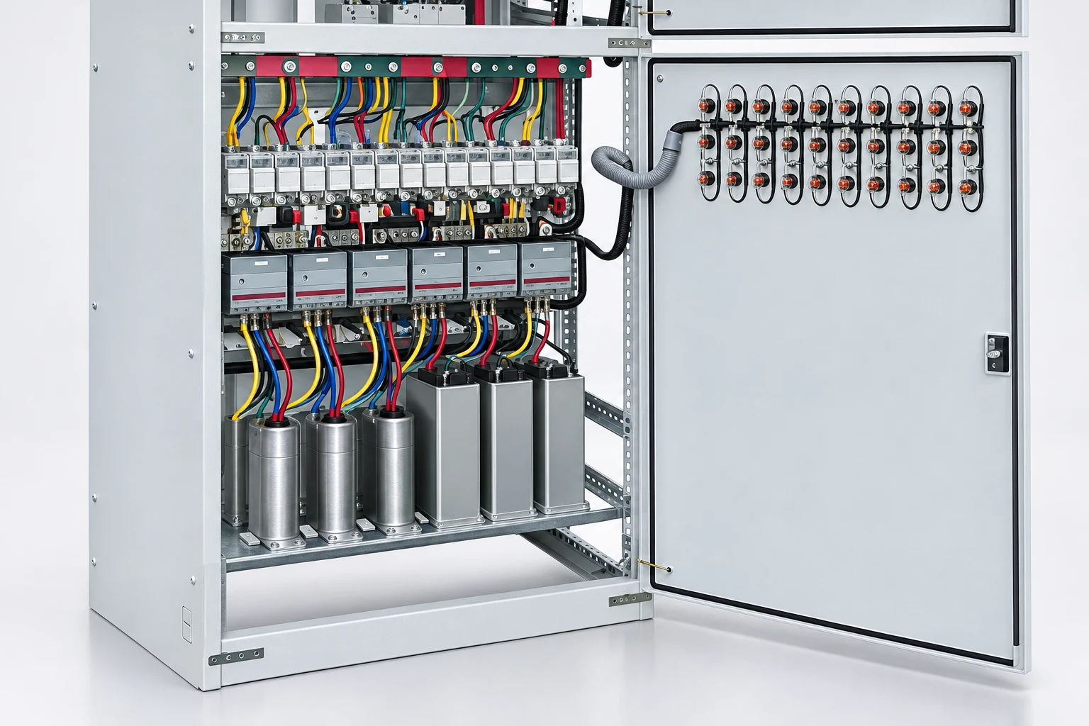
Include rated supply voltage and frequency, fault level, enclosure location, ambient temperature, cable entry and access constraints. Request the assembly’s relevant documentation, component list, protective-device arrangement and test records. Capacitor can ratings alone do not establish the suitability of the completed cabinet. The short-circuit and thermal design must address the actual assembly.
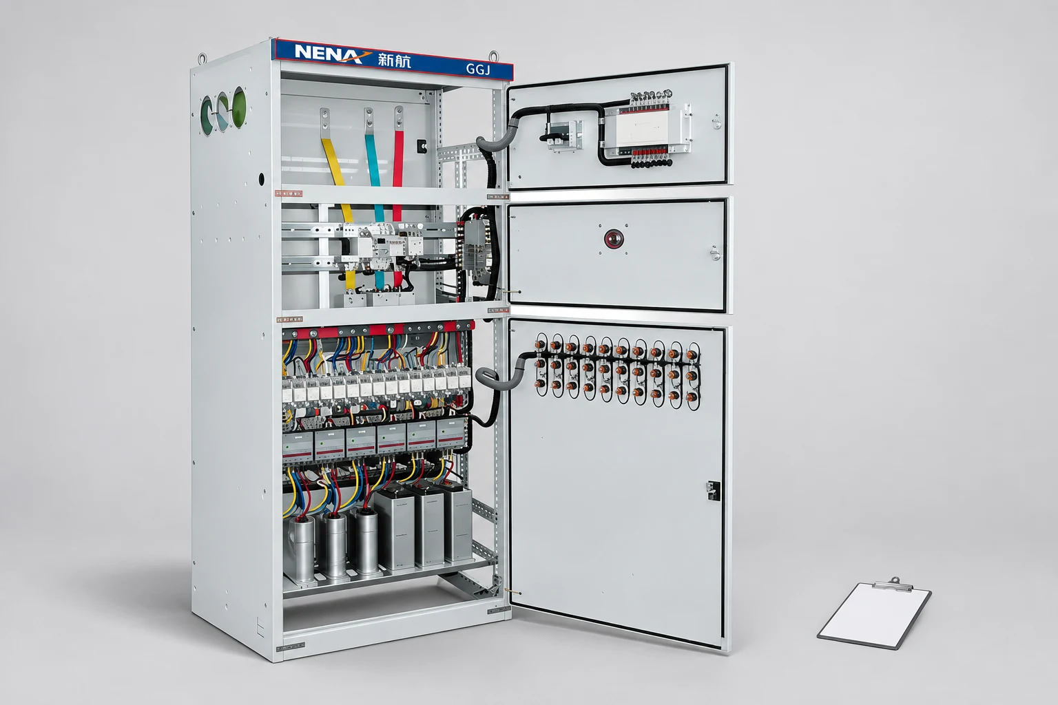
NENA’s GGJ reactive compensation device provides a relevant product starting point. Its reference photographs show the visible cabinet and component arrangement, not a confirmed kvar rating or harmonic-treatment capability. Provide the measurement package and request a project-specific technical response.
The cabinet selection guide helps organize the broader supply boundary. Review how motor starting and speed-control choices change the load mix, and coordinate physical installation with the temperature and altitude checks for drives. Correction equipment should be evaluated within that complete distribution system.
Agree on the acceptance measurement point and load conditions before the panel arrives. Record stage currents, controller readings, alarm behaviour and the power-quality measurements required by the design. Observe light-load operation as well as full production. A displayed target number is insufficient if the bank hunts between stages or fails to release compensation when demand falls.
Keep the final drawing, controller settings, test records and maintenance instructions together. Reassess the correction arrangement after adding drives, changing transformers or materially altering production. These changes can affect both reactive demand and harmonic behaviour, even when the original capacitor bank remains mechanically intact.
Suppose the initial kvar estimate is based on a busy production period, but most motors stop overnight. An automatic bank needs sufficiently fine stages and appropriate sensing to follow the reduced demand. A fixed bank selected from the production peak may remain connected when little inductive demand is present. Ask bidders to show the proposed response at both operating points, including the minimum stage and controller measurement location.
Also identify existing local motor capacitors. If they switch with individual machines, their contribution changes with production. The new central panel must be assessed together with them. This is why a measurement log should state which equipment and capacitor stages were operating, rather than supplying only an unexplained power-factor screenshot.
The neutral educational lecture below explains the basic power triangle and correction principle. It supports the preliminary calculation, while site measurements and engineering review determine the panel specification.
No. The transformer rating does not describe the actual load power factor or its variation. Use representative measured load data and review the network and harmonics.
No. Choose a target that suits the tariff, operating profile and control capability while avoiding leading operation and unnecessary switching.
An ordinary bank is not a general harmonic filter. The interaction between capacitance and network impedance must be assessed before selecting a compensation arrangement.
Include the load profile, power-factor definitions, harmonic measurements, supply ratings, fault level, transformer data, existing compensation and installation conditions.