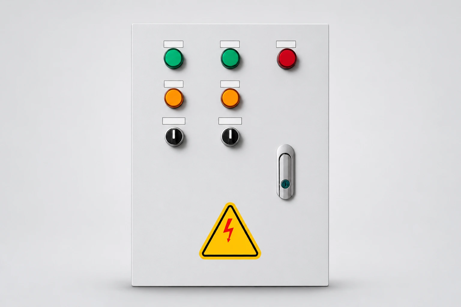
Permanent magnet motor back EMF is voltage induced by rotor motion. A motor driven by a fan, flowing water or another mechanical source can therefore generate voltage even after its normal electrical supply has been disconnected. For maintenance planning, distinguish the drive’s stored electrical energy from energy produced by continued shaft rotation. A stopped command, a dark display and a completed discharge waiting time do not establish the same condition. Identify the complete drive and motor arrangement, control possible mechanical movement and verify the electrical condition through the authorized procedure before work begins.
The magnets provide rotor flux without requiring the normal drive supply to create that flux. When the rotor moves relative to the stator windings, an induced voltage can appear. Its value depends on the motor design and speed. This is an operating principle, not a claim that every rotating PM motor produces the same voltage or that a particular speed is safe.
В руководстве по эксплуатации Lund University PMSM study explains the relationship between rotor motion, flux linkage and induced voltage. Its prototype results are specific to that research. They should not be used as settings or voltage limits for an industrial motor connected to an 860E drive.
A separate safety framework is needed to turn that principle into a maintenance method. The HSE electrical safe working guidance addresses planning, isolation and verification. The equipment manufacturer and the site’s competent electrical authority must define the procedure for the actual system and jurisdiction.
| Условие | What it tells you | What still needs confirmation |
|---|---|---|
| Drive has received a stop command | A control instruction has been issued | Actual motion, power state and the intended stopping function |
| Incoming electrical supply is isolated | A defined supply path has been interrupted | Other supplies, stored energy and motor-generated voltage |
| Specified discharge interval has elapsed | The stated waiting period has passed | Required verification at the relevant points and any continuing generation |
| Mechanical load cannot rotate the shaft | A potential motion source has been controlled | The remaining electrical condition and all other energy sources |
The table separates questions for a work plan; it is not a switching sequence. The physical principle comes from the university reference, while the work-control boundary follows the HSE guidance. A competent person must decide how those questions apply to the actual equipment.
A fan can move because air is passing through it. A pump can be influenced by fluid movement. Other loads can store mechanical energy or be coupled to an adjacent machine. At the planning stage, ask the process owner whether the shaft can move when its usual supply is unavailable. Do not limit the question to whether the motor has received a run command.
Describe the credible operating conditions. An idle fan during a still day may behave differently when another fan starts. A pump that appears stationary during inspection may rotate after a valve or process condition changes. These are scenarios for the responsible engineers to assess, not reasons to test rotation by hand or alter a process isolation without authorization.
Record which person controls each process boundary and how that control will be maintained during the work. Electrical and mechanical teams should work from the same equipment identity and scope. If one team assumes the other has prevented movement, the paperwork can look complete while the underlying question remains unanswered.
A drive may specify a waiting period for internal stored energy to dissipate. That instruction belongs to the exact model and must be followed. It does not automatically account for a mechanically driven motor that can generate again. A waiting period and a verified absence of hazardous voltage answer different questions.
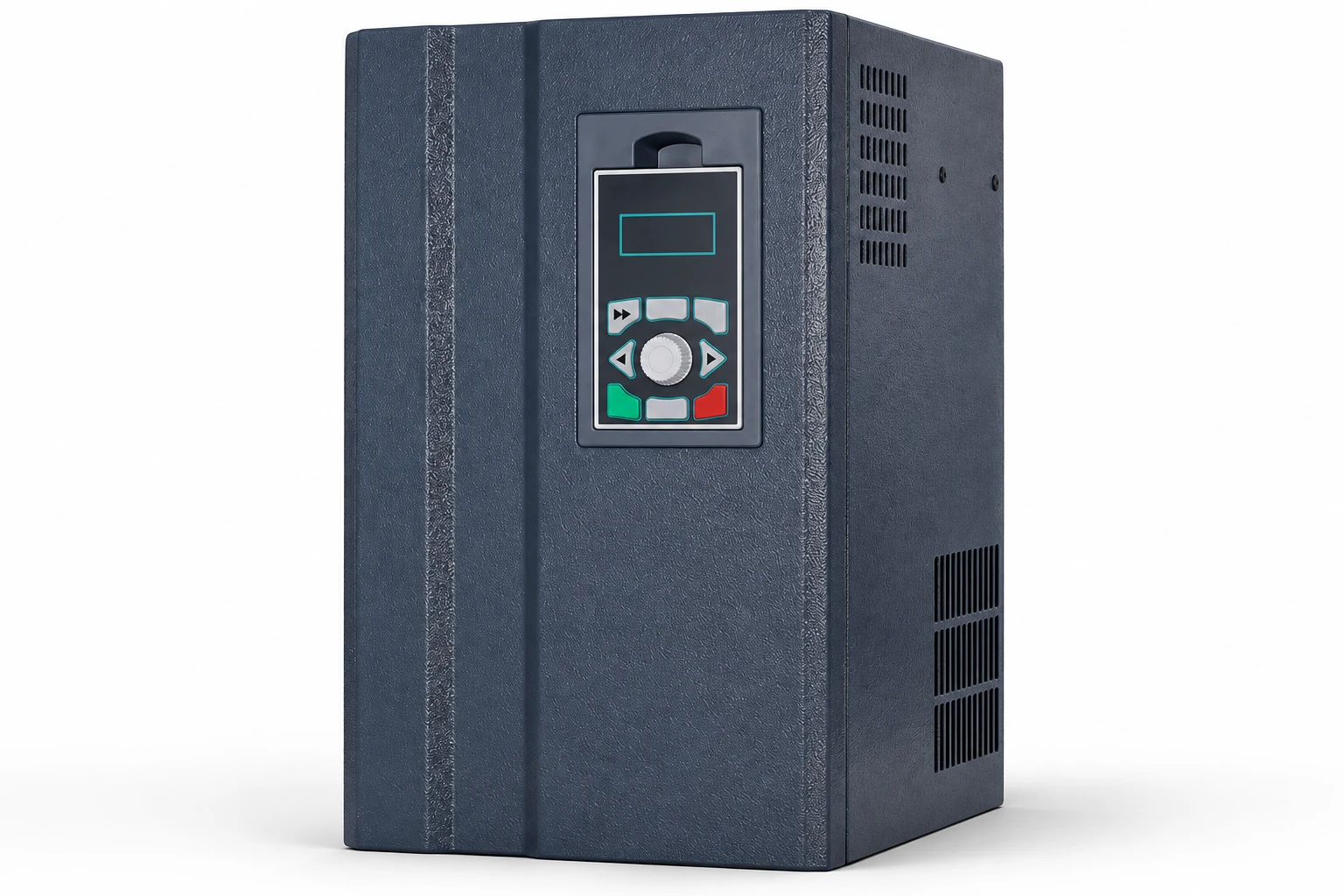
Do not read a time printed on a photograph and apply it to another unit. Product families, ratings and revisions can differ. Obtain the correct installation and service manual, then identify every warning relevant to motor movement, output connections and discharge verification. If documents conflict with the supplied equipment labels, resolve the discrepancy with the manufacturer before work.
A dark keypad is also insufficient evidence. It is an interface condition, not a measurement of every circuit. Similarly, a display reading of zero speed may depend on its sensing method or operating state. The authorized procedure should establish what observations are useful and what verification is still required at the work location.
When discussing back EMF with a supplier, provide the exact motor model, rated speed and the manufacturer’s definition of its voltage constant. Values stated per mechanical speed, electrical angular speed, phase voltage or line voltage cannot be substituted without checking their definitions. Peak and RMS quantities also need to remain distinct.
For illustration only, if a documented line-to-line RMS constant were 40 V per 1,000 rpm, a proportional no-load estimate at 750 rpm would be 30 V using the same definition. This is arithmetic, not a measurement or a safety threshold. Temperature, waveform, loading and the connected circuit require appropriate engineering consideration. No such constant is claimed for the NENA product pictured here.
Use that example to improve the information request, not to authorize work. Ask the motor supplier to explain the applicable constant and conditions. If the correct data are unavailable, do not infer them from motor size, nameplate power or a generic internet table. A result with the wrong voltage definition can look precise while answering the wrong question.
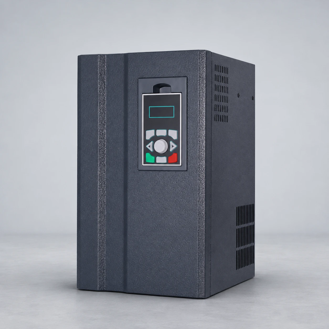
A drive can provide useful stopping, control or diagnostic functions. Their availability and safety classification depend on the exact product and the integrated system. Do not assume that a general-purpose digital input, a keypad stop or a configured speed command establishes a maintenance isolation boundary. Obtain the relevant function documentation and system assessment.
В руководстве по эксплуатации motor autotune guide concerns identifying motor behavior for control. It does not establish the absence of voltage during service. Likewise, the drive deceleration overvoltage article addresses an operating fault mechanism. A successful deceleration test is not a substitute for work preparation.
Where a designer proposes additional switching, blocking or mechanical restraint, require a documented equipment-specific design. This article does not recommend opening a motor-side contactor under load, shorting motor terminals or adding a braking component. Such actions can create new risks and need the manufacturer’s explicit engineering guidance.
Send a system sketch that identifies the electrical supply, drive, motor and driven equipment. Add the relevant manuals, installed modifications, process conditions that can create motion and the proposed work location. Distinguish work inside the drive from work on the motor cable or the driven load. The same installation can require different boundaries for different tasks.
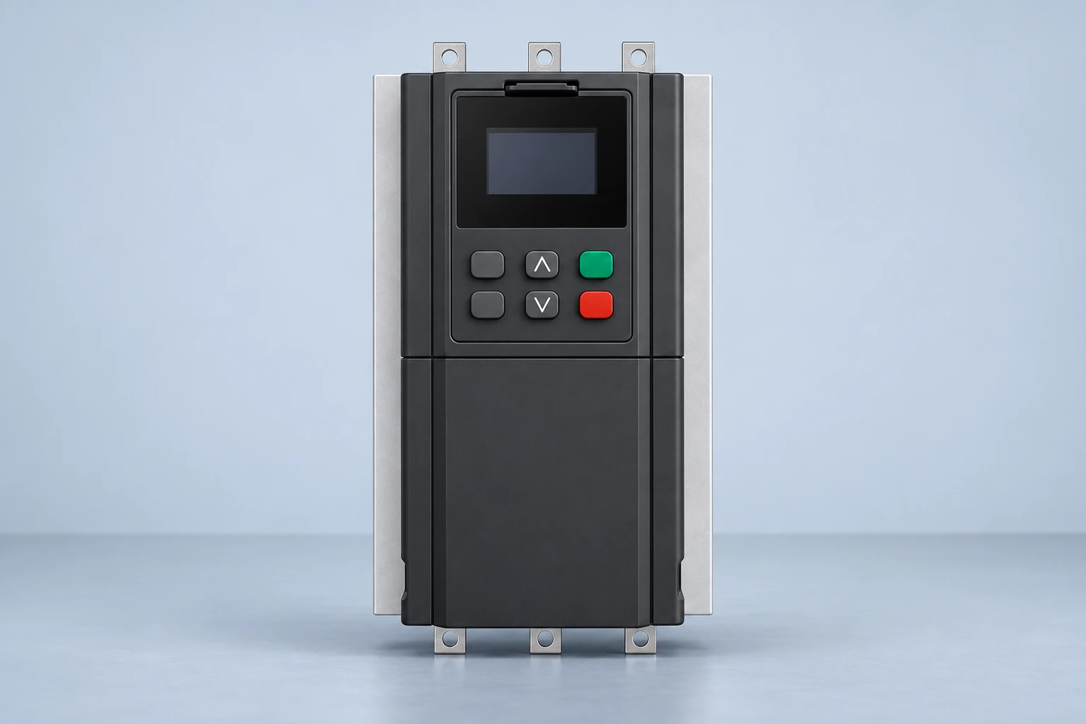
NENA lists an 860E permanent magnet synchronous VFD. Confirm its exact configuration, supported motor and service instructions rather than transferring assumptions from an induction-motor installation. The exterior reference illustrations do not show internal safety circuits or establish a particular stop-function certification.
For basic system context, the руководство по выбору инвертора для двигателя helps organize a compatibility discussion. At handover, keep the approved procedure and equipment revisions together. Update them after changes to the motor, drive, process or mechanical coupling; an old procedure may no longer describe the installed arrangement.
A maintenance task can expand after a cover is removed or a damaged connection is discovered. If the work moves from an external accessory to motor terminals or drive internals, reassess the boundary before continuing. The original authorization may have addressed a different location and different energy sources. Record the changed scope and obtain the equipment-specific method from the responsible team.
After a motor or drive replacement, review the documents again. A new unit can change the applicable discharge instruction, voltage data or mechanical interface. Retaining the previous procedure without checking those differences creates an avoidable gap. The useful handover record names the installed equipment, the approved document revisions and the process conditions considered, so a future team can understand what the procedure actually covers.
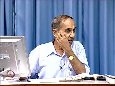
The NPTEL lecture below provides academic background on synchronous permanent magnet machines. It supports understanding of the motor principle. It is not a service demonstration, an 860E parameter guide or permission to perform an electrical test.
Смотрите на YouTube — NPTEL IIT Delhi
Yes, shaft rotation can induce voltage. The actual condition depends on the motor and connected system and must be assessed through the approved procedure.
No. Follow the specified wait, but also account for other supplies and possible motor rotation. Required verification remains necessary.
No. Use the correct motor data and its exact voltage and speed definitions. A generic value cannot establish a safe condition.
Ask whether process conditions or another mechanical source can rotate the shaft while work is underway, and have the responsible team define the required controls.