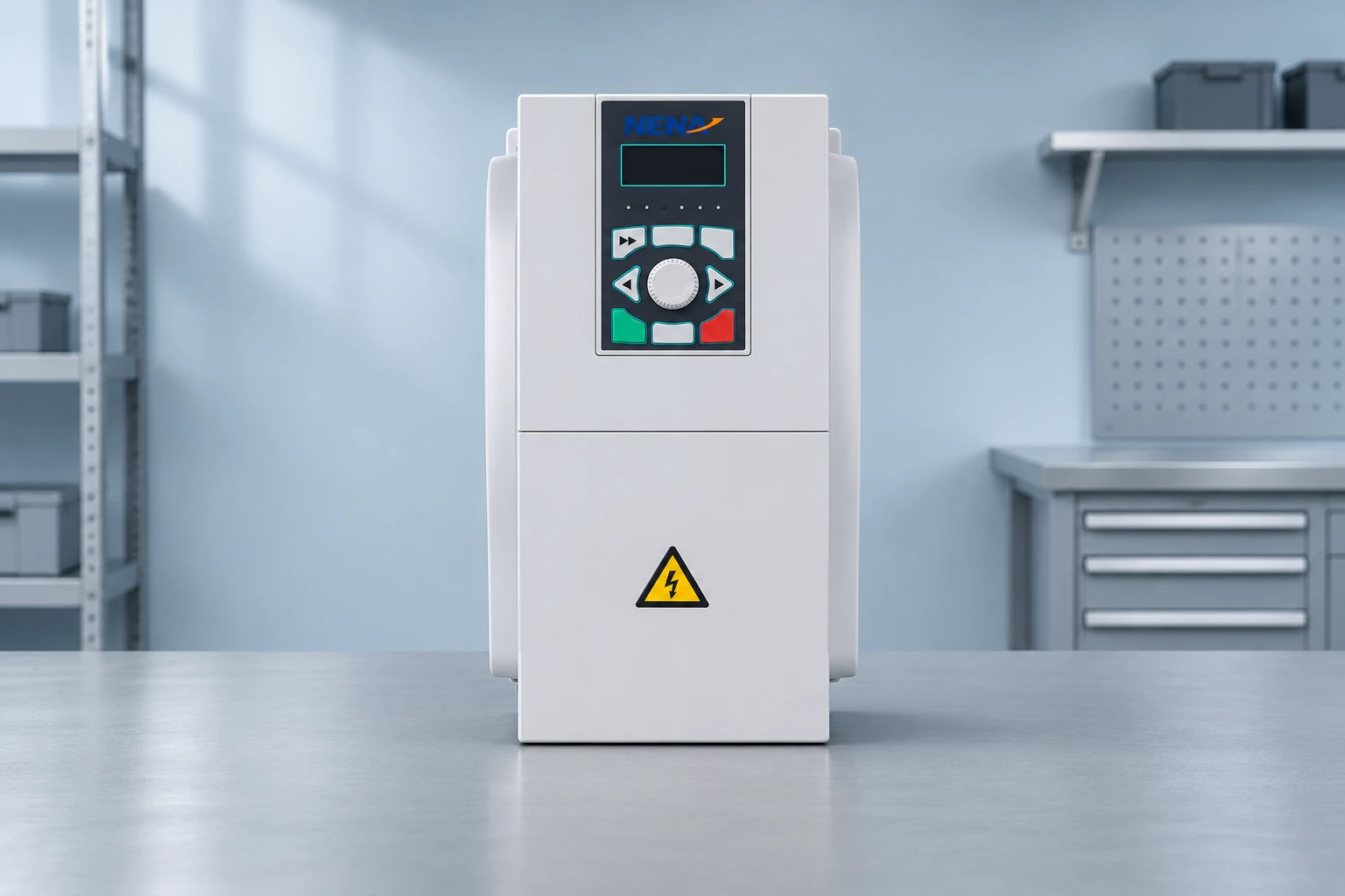
Capacitor bank low load overcompensation occurs when connected capacitive reactive power exceeds the inductive demand remaining at that operating point. A bank that performs well during production can therefore produce leading operation at night or after large machines stop. Start by confirming the meter’s sign convention, measurement location and actual capacitor-stage state. Then compare minimum-load demand with the compensation that remains connected. Do not respond to an unexplained power-factor value by adding more capacitors or changing the target blindly. This guide explains the evidence needed for a controlled engineering review, rather than prescribing a universal controller setting.
Industrial load is not constant. Motors, transformers and other equipment contribute different amounts of real and reactive demand as production changes. If capacitors remain connected while the relevant inductive demand falls, their contribution can exceed what is needed at the measurement point. The installation may cross from lagging to leading operation even though no capacitor has failed.
El DOE guide to reducing power-factor cost explains the distinction between useful real power and reactive demand, and the role of capacitors. For a practical review, add the operating timeline: which machines stopped, which compensation remained available, and which supply source was active when the reported condition changed.
Keep this diagnosis separate from general bank sizing. A maximum-production calculation can estimate one operating point but cannot establish acceptable behavior at minimum demand. The power-factor correction panel sizing guide provides the wider purchasing framework. Here, the question is narrower: what remains connected when the plant needs the least compensation?
Different instruments can present reactive direction and power-factor signs differently. A minus sign alone does not establish overcompensation. Record the instrument model, displayed quantity, connection point and the manufacturer’s convention. Identify whether the displayed power factor is a true power factor or a displacement-related value, especially where converters and other nonlinear loads are present.
Compare synchronized observations rather than screenshots from different times. The main incomer meter and the capacitor controller may observe different boundaries. One may include feeders that the other does not. A control display can also represent a command or calculated state rather than proof that a physical stage has disconnected. Document what each indication actually means.
Have qualified personnel verify measurement configuration where evidence is inconsistent. Current-transformer ratio, phase association, polarity and sensing location belong in that assessment. Do not suggest reversing live instrument wiring as a trial. Changes to measurement circuits need the approved procedure and appropriate precautions, including the particular hazards associated with current-transformer circuits.
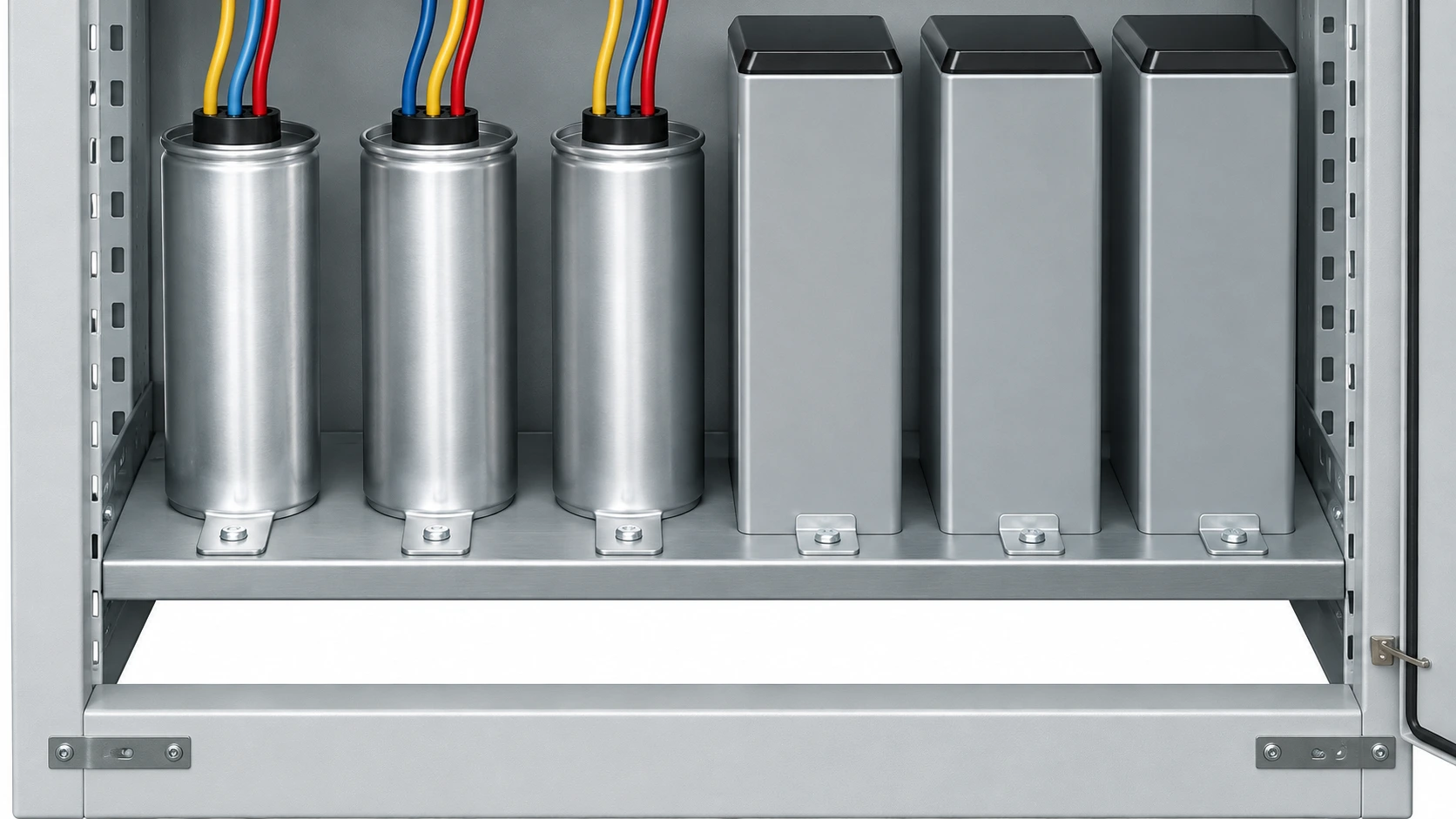
For a simplified sinusoidal operating point, define inductive load reactive power as positive. Let Qload be that load demand in kvar and Qcap be the positive magnitude supplied by connected capacitors. Then Qnet = Qload − Qcap. A negative result under this chosen convention means net capacitive, or leading, operation. The meter’s own sign convention must still be checked.
Suppose a low-load condition has P = 40 kW and Qload = 12 kvar. If a 20 kvar stage remains connected, Qnet = 12 − 20 = −8 kvar. Under the same simplified assumptions, apparent power is S = √(P² + Qnet²) = √(40² + 8²), approximately 40.79 kVA. The power-factor magnitude is P/S, approximately 0.981, but the operating point is leading.
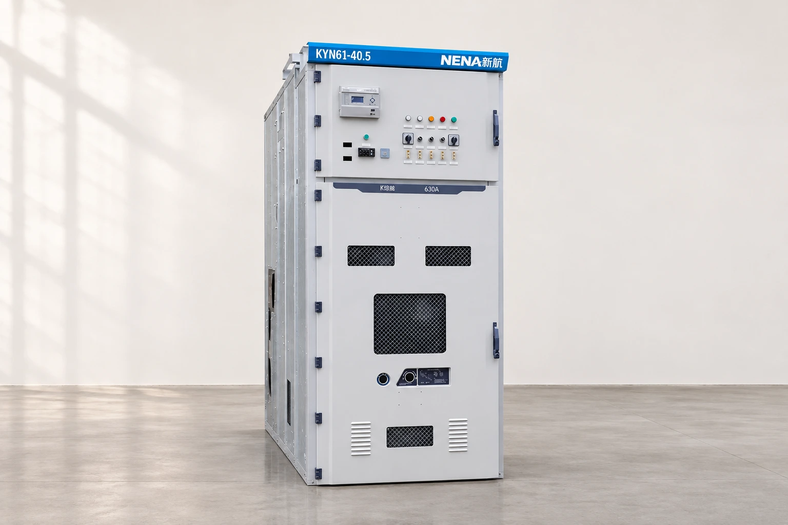
These are invented teaching inputs, not measurements or ratings for a NENA cabinet. The example shows why a value close to one can still require attention to reactive direction. It omits harmonic distortion, imbalance, instrument error and dynamic switching. Do not use it to specify a stage size or declare a utility requirement satisfied; use measured conditions and the applicable tariff and equipment requirements.
Choose a survey period that actually includes reduced production, shutdown transitions and other relevant low-load conditions. Note the active supply source and any local compensation outside the central bank. Use suitable instruments and qualified personnel. The goal is a time-aligned record that can connect an observation to the plant state, rather than a collection of isolated power-factor numbers.
| Patrón observado | Possible explanation | Evidence needed before changing settings |
|---|---|---|
| Leading operation appears after machines stop | Connected compensation exceeds remaining inductive demand | Minimum-load kW and kvar with actual stage states and local capacitors identified |
| Controller reports stages off but leading demand remains | Other capacitive sources, a stage-state discrepancy or measurement configuration issue | Measurement boundary, stage verification and controller indication definitions |
| One available stage changes lagging operation to leading | Compensation resolution may be too coarse for that operating point | Documented stage output, low-load profile and control requirements |
| Readings disagree between two instruments | cURL Too many subrequests by single Worker invocation. To configure this limit, refer to https://developers.cloudflare.com/workers/wrangler/configuration/#limits | cURL Too many subrequests by single Worker invocation. To configure this limit, refer to https://developers.cloudflare.com/workers/wrangler/configuration/#limits |
| cURL Too many subrequests by single Worker invocation. To configure this limit, refer to https://developers.cloudflare.com/workers/wrangler/configuration/#limits | cURL Too many subrequests by single Worker invocation. To configure this limit, refer to https://developers.cloudflare.com/workers/wrangler/configuration/#limits | cURL Too many subrequests by single Worker invocation. To configure this limit, refer to https://developers.cloudflare.com/workers/wrangler/configuration/#limits |
cURL Too many subrequests by single Worker invocation. To configure this limit, refer to https://developers.cloudflare.com/workers/wrangler/configuration/#limits cURL Too many subrequests by single Worker invocation. To configure this limit, refer to https://developers.cloudflare.com/workers/wrangler/configuration/#limits cURL Too many subrequests by single Worker invocation. To configure this limit, refer to https://developers.cloudflare.com/workers/wrangler/configuration/#limits.
First establish the compensation that cannot automatically leave service. This can include fixed central capacity and local capacitors elsewhere in the installation. Next identify the smallest effective change the automatic arrangement can make. A large total bank is not necessarily unsuitable if it can follow the load; a small fixed contribution can still be excessive during an unusually low-demand period.
Review physical behavior separately from the controller’s requested state. An approved investigation may need to establish whether a switching device and its associated stage follow the command. The test method must suit the assembly, its discharge arrangements and the site procedure. Do not encourage manual repeated switching or opening a cabinet as a way to experiment with a live compensation problem.
El capacitor-bank hunting guide addresses repetitive switching, which can coexist with low-load overcompensation but is not identical to it. The capacitor discharge-time guide explains why reconnection delays and safe maintenance access require equipment-specific evidence. Shortening a delay is not a substitute for resolving an unsuitable compensation arrangement.
Ordinary capacitors do not correct every cause of poor true power factor. Where waveform distortion is significant, a displacement-only calculation can mislead the selection. Retain the harmonic measurements and network information needed by the engineer before deciding whether the issue is excessive fundamental-frequency compensation, measurement interpretation or another power-quality problem.
Also record generator operation, transformer changes and other source configurations. A compensation arrangement accepted for the normal utility supply is not automatically approved for every alternate source. Ask the relevant equipment designers to review operating modes and interlocks together. Do not infer a permitted leading operating range from an unrelated generator or from an apparently stable short test.
The decision should state what has been established and what remains uncertain. If the log confirms excess fixed capacity, coarse stage resolution or a stage failing to leave service, address that identified cause through an approved design or repair. If the evidence does not distinguish those possibilities, improve the survey before buying replacement hardware.
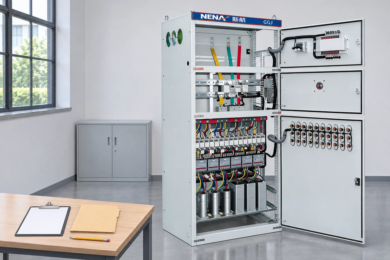
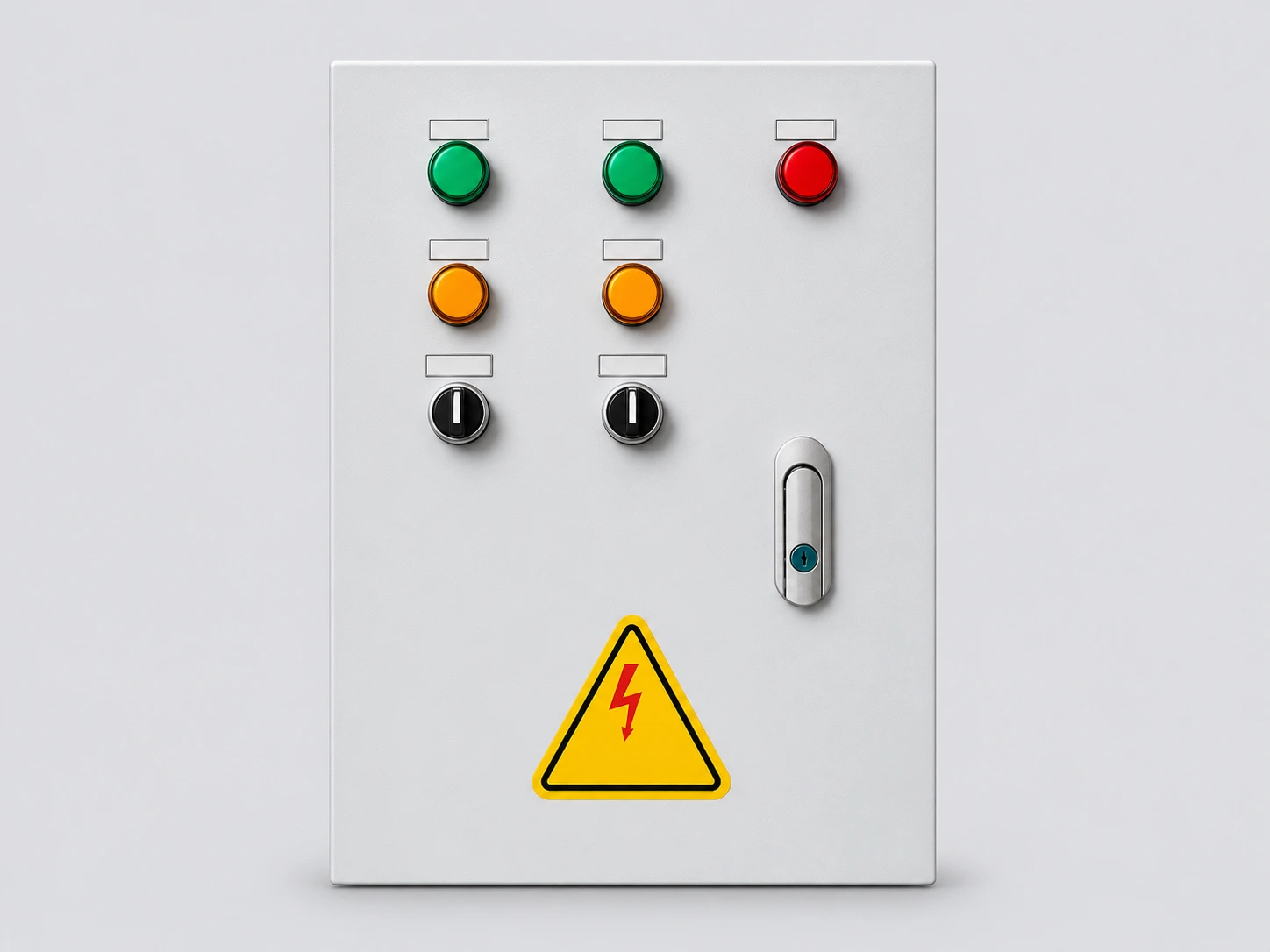
Para un GGJ reactive compensation cabinet, provide the actual assembly identification and approved documents, not just its enclosure photograph. Include the single-line diagram, minimum and normal load records, stage schedule, controller information, existing local capacitors, harmonic survey and supply modes. Ask the supplier to distinguish confirmed supplied functions from proposed modifications.
Define success with the responsible engineer and utility requirements: the operating periods covered, allowed reactive behavior, control response and evidence to retain after the change. Do not promise a specific bill reduction from one improved display value. Billing intervals, tariff definitions and the measurement boundary determine the commercial assessment.
Follow HSE’s principles for planned maintenance and safe isolation when arranging investigation or repair. Capacitor equipment requires the manufacturer’s stored-energy precautions in addition to supply isolation. Keep the final settings, drawings and verification record together so a later shift or contractor can understand why the accepted arrangement differs from the original one.
Jim Pytel’s neutral educational lecture explains power-factor correction and the power triangle. It supports the simple calculation above. The classroom circuit is not a design approval for an industrial bank, and it does not establish acceptable reactive limits for a particular site or electricity contract.
Yes. If inductive demand falls while compensation remains connected, the low-load condition can become leading. Review the full operating profile and the capacity that can actually disconnect.
No. Confirm the instrument's sign convention, power direction, measurement definition and configuration before interpreting a negative display.
Only after identifying the cause through suitable measurements and engineering review. Excess compensation, distortion or measurement errors require different responses.
No. Fixed capacity, stage resolution, failed switching or other capacitive sources may remain outside what a target change can solve. Verify the actual cause and approve the corrective action.