Duty standby pump failover means transferring a continuing pumping demand to an available standby unit after a defined failure of the duty unit. It requires more than alternating the lead pump at the next normal start. A useful specification states what counts as failure, which conditions allow the second pump to start, how restored pumping is verified and what happens to the failed pump afterward. This guide helps buyers and commissioning teams write that sequence. It does not establish that every two-pump control box has automatic failover, and it does not replace the supplied circuit drawings or the site’s safe work procedure.
Alternation distributes normal duty between pumps. Assistance starts another pump when demand exceeds the current operating arrangement, if the design permits combined operation. Failover responds to a defined failure. These actions can coexist, but they answer different questions and need separate acceptance checks. A successful alternating cycle does not demonstrate response to a duty pump fault.
Write the intended role of each pump in plain language before discussing relays or software. State whether one pump is normally sufficient, whether both may run together and whether either unit may be designated unavailable. Check the hydraulic design as well as the electrical sequence. Starting a second motor is not enough if the connected process cannot accept the resulting operating condition.
Our guía de alternancia de bombas dúplex covers normal lead rotation. Use it alongside this failure-response scope, keeping the acceptance evidence for each function distinct.
Possible observations include a protective trip, an unavailable motor starter, absence of the required running feedback or failure of the expected process response. The approved design determines which observations initiate transfer and how they are assessed. Do not assume a fault lamp represents every failure mode or that a motor running indication proves water is moving.
For each initiating condition, identify the source, meaning and permitted response. A drive fault contact and a pressure failure can indicate different problems. One may concern a single unit while the other may reveal a blocked common discharge, unavailable water supply or another shared condition. Automatically transferring without understanding common restrictions can leave the second pump exposed to the same problem.
Separate command from feedback in the records. The article on pump run feedback mismatch explains why an issued start request and actual operating evidence should not be treated as identical.
The standby unit must be eligible to run under the actual design. Check its selected operating mode, maintenance status, required permissives and protection state. A pump isolated for maintenance must not become available simply because the other pump fails. Document how maintenance unavailability is represented and communicated to operations.
Consider shared resources explicitly. Two pumps may depend on one incoming supply, one control supply, one sensor or one common pipe route. The owner must understand which failures the arrangement can tolerate and which can stop both units. Two installed pumps do not by themselves establish an independent or fault-tolerant system.
Seattle Public Utilities’ pump station design chapter is an example of a municipal owner’s detailed design framework. Its treatment of station operation, instrumentation and reliability illustrates why the complete process matters. It is not a universal control sequence or a product approval for the cabinet shown here.
The following table is a specification template. Replace each decision with the project-approved response before commissioning. No universal delay or pressure threshold is supplied because those values depend on the equipment, operating duty and consequences of interruption.
| Etapa | Pregunta a resolver | Evidence to record |
|---|---|---|
| Normal demand | Which pump is duty and is demand still present? | Demand source, selected duty and current state |
| Failure recognition | Which defined condition initiates transfer? | Initiating signal, event time and interpretation |
| Standby eligibility | Is the second unit available and permitted to run? | Mode, protections and required permissives |
| Transfer request | What sequence and approved timing apply? | Issued commands and relevant state transitions |
| Restored service | What confirms useful pumping has resumed? | Running evidence and required process response |
| Unsuccessful transfer | Which alarm and operator response follow? | Alarm delivery, retained state and escalation |
| Recovery | Who may return the failed unit to availability? | cURL Too many subrequests by single Worker invocation. To configure this limit, refer to https://developers.cloudflare.com/workers/wrangler/configuration/#limits |
cURL Too many subrequests by single Worker invocation. To configure this limit, refer to https://developers.cloudflare.com/workers/wrangler/configuration/#limits.
cURL Too many subrequests by single Worker invocation. To configure this limit, refer to https://developers.cloudflare.com/workers/wrangler/configuration/#limits.
cURL Too many subrequests by single Worker invocation. To configure this limit, refer to https://developers.cloudflare.com/workers/wrangler/configuration/#limits.
cURL Too many subrequests by single Worker invocation. To configure this limit, refer to https://developers.cloudflare.com/workers/wrangler/configuration/#limits cURL Too many subrequests by single Worker invocation. To configure this limit, refer to https://developers.cloudflare.com/workers/wrangler/configuration/#limits cURL Too many subrequests by single Worker invocation. To configure this limit, refer to https://developers.cloudflare.com/workers/wrangler/configuration/#limits.
Prepare an approved test method that states the safe process conditions, people responsible, permitted simulation points and expected outcomes. Do not improvise a test by opening a live circuit, blocking a pump or defeating a protective device. Decide in advance how each test ends and how the system returns to its accepted operating mode.
HSE’s maintenance guidance supports competent personnel and planned control of hazards. Its safe electrical working practices guide provides additional context for electrical work. Apply the site’s specific procedures, including the hydraulic and mechanical work boundary where relevant.
Cover both directions of transfer if either pump can be duty. Include an unavailable standby condition and the required alarm response. If the agreed test uses simulated feedback, state that limitation explicitly. Simulation can demonstrate selected logic behavior without proving the real sensor, motor, hydraulic path and field wiring together.
Define useful pumping through the evidence required for the actual application. That may involve a documented level trend, pressure response or flow observation. A contactor auxiliary contact can support electrical status, but it cannot establish every process outcome. Record the meaning and limits of each feedback source so future troubleshooting does not rely on an exaggerated signal description.
Use time-aligned records during the trial. Note the initial demand, failure event, transfer request, running feedback and process response in sequence. The responsible designer should set any required timing criteria. This article intentionally supplies no generic acceptable transfer time because the consequences and system behavior vary by installation.
Record what was not demonstrated. A low-demand trial may leave high-demand performance untested, and a controller simulation may leave field fault detection untested. Those are specific remaining tasks, not reasons to label the entire installed system as verified.
After the fault is resolved, specify whether the repaired pump remains unavailable until manual release or returns through an approved automatic sequence. Define what happens to the currently running pump and retained duty selection. Avoid repeated reset attempts without addressing the cause. The next operator should be able to understand why a pump is available, unavailable or still requiring attention.
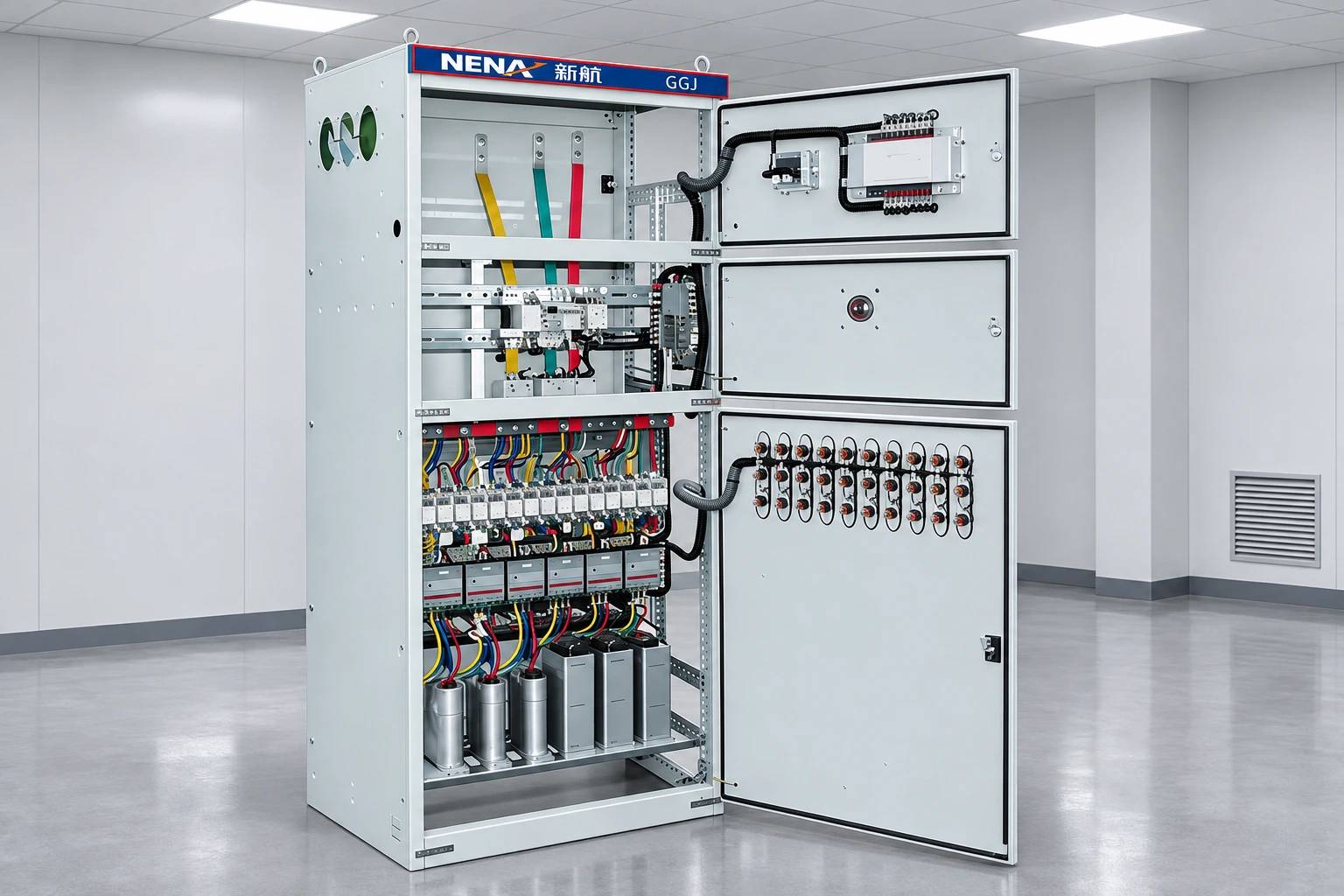
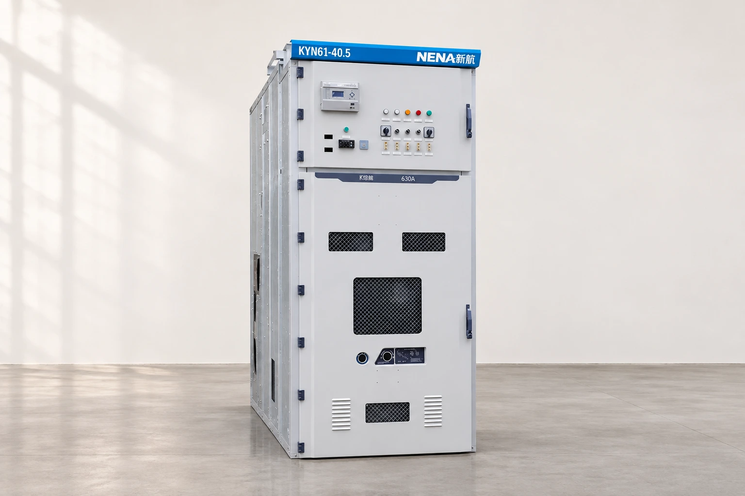
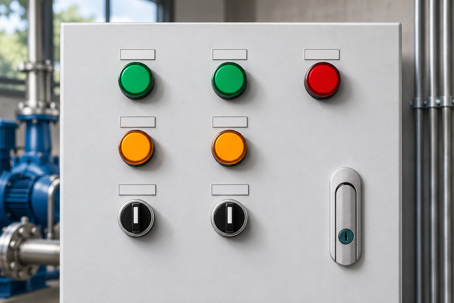
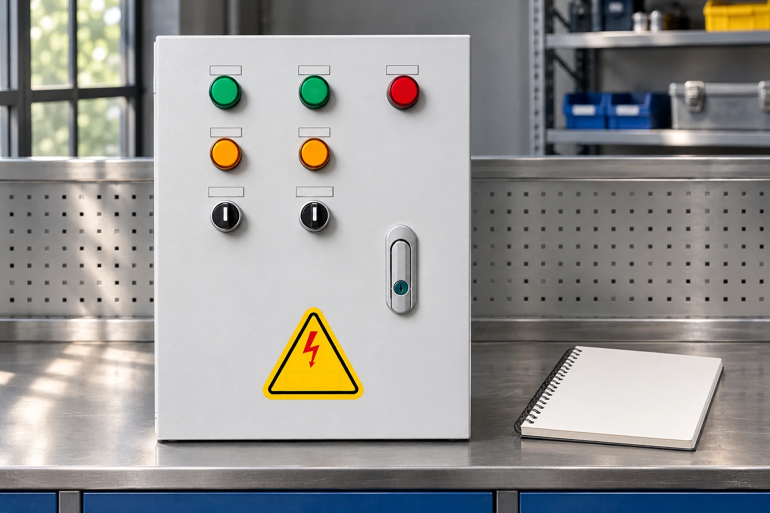
El NENA one-to-two water pump control box is the product reference for these illustrations. Confirm automatic transfer capability, required interfaces and actual supplied logic in writing. The two-pump front panel and selector switches alone do not prove that a particular failure-response function is fitted.
Provide the supplier with motor data, supply details, pump duty, process drawings, demand and feedback signals, alarm destinations and the completed sequence table. Request drawings and a proposed acceptance scope. The resulting inquiry gives the supplier concrete functions to confirm and makes any exclusions visible before the cabinet arrives.
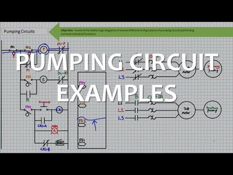
Jim Pytel’s educational lecture below explains pumping circuit examples. It helps readers understand the relationship between inputs and operating requests. It is background education, not the circuit diagram for the NENA box or permission to alter installed controls.
No. Alternation distributes normal duty; failover responds to a defined failure while pumping demand continues.
No. Standby availability, shared dependencies and the actual hydraulic process determine which failures the arrangement can tolerate.
No. Confirm the specified electrical feedback and the required process response. A lamp's meaning must be documented.
No. Record exactly what simulation demonstrated and separately verify any field detection, wiring and process behavior excluded from the test.