

Integrated Power Mete
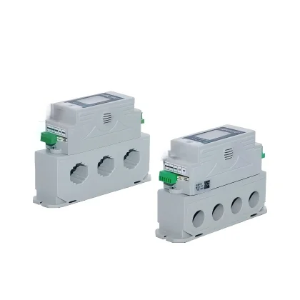
Product Overview The GGC6 series is an intelligent digital product developed by our company based on next-generation communication and sensing measurement technologies. It has built-in sensors for current, voltage, temperature, zero sequence, etc., which can accurately collect various power consumption and environmental data on site. It also has a built-in communication module…
Product Overview
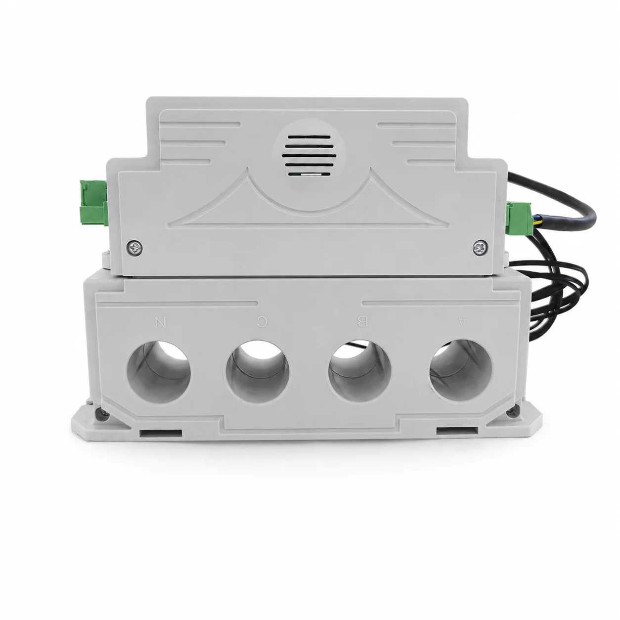
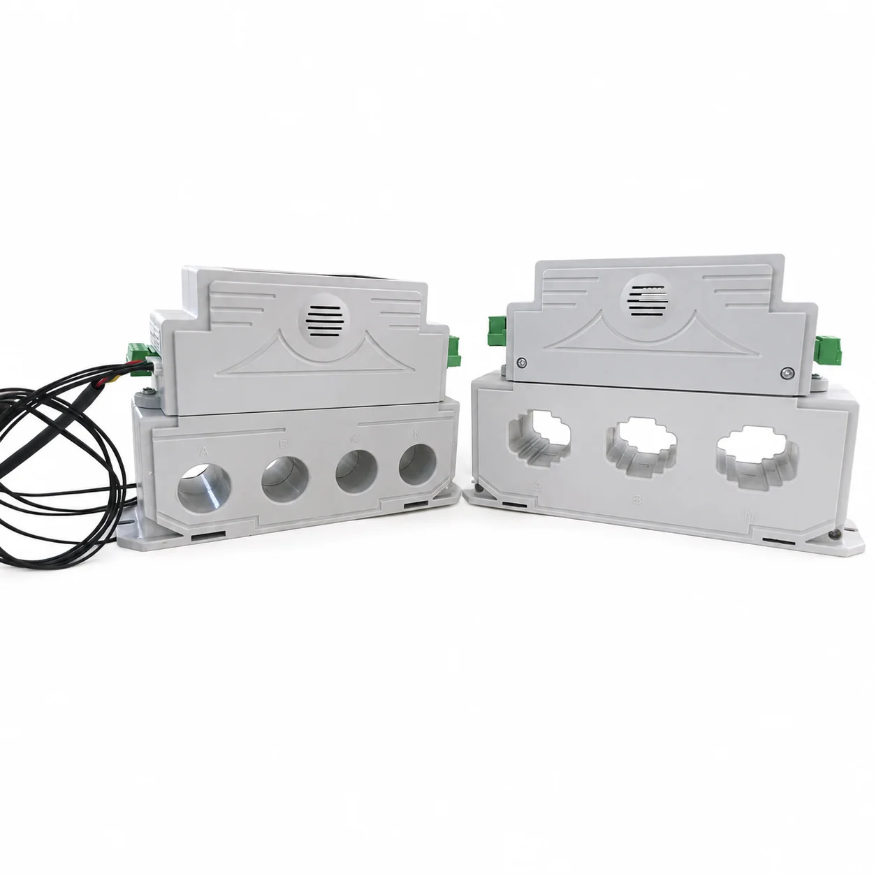
The GGC6 series is an intelligent digital product developed by our company based on next-generation communication and sensing measurement technologies. It has built-in sensors for current, voltage, temperature, zero sequence, etc., which can accurately collect various power consumption and environmental data on site. It also has a built-in communication module that supports various communication methods based on modern mobile or wired networks.
This product is suitable for AC power networks with rated voltages of AC220V/380V and frequencies of 50Hz/60Hz. Its integrated design features high reliability, low power consumption, small size, easy installation, and standardized specifications. It seamlessly integrates with existing power distribution systems and digitizes and upgrades legacy electrical fire and fire protection power supply monitoring systems. Compared to traditional distributed monitoring solutions with complex wiring, low installation efficiency, and time-consuming processes, this product offers unparalleled advantages.
Product Standards
GB/T17215.301-2007 Special Requirements for Multifunctional Energy Meters
GB/T17215.322-2008 Static active energy meters (Class 0.2S and Class 0.5S)
GB/T17215.323-2008 Static reactive energy meters (Class 2 and Class 3)
DL/T614-2007 Multifunctional Energy Meter
Main Technical Parameters
- Operating power supply: AC220V 50Hz/60Hz
- Working environment: -30~80℃
- Operating humidity: ≤ 95%RH, non-condensing.
- Working altitude: ≤2500 meters
- Communication method: RS485 x 2
- Ø1 input: 1 passive opening/closing signal detection input
- Ø2-channel output: 2 relay outputs, with selectable output mode.
- Remote control: Remote opening/closing (4G, RS485)
- Measurement range: Three-phase four-wire voltage 0~400V
- Three-phase current 0~800A
- Temperature -55~150℃
Product Features
● LCD display with Chinese interface and menu-driven button operation for a user-friendly experience.
●Performs 24-hour continuous, cyclic data collection and upload of primary circuit parameters such as voltage, current, power, power factor, power consumption, ground fault, energy consumption, and temperature;
●Alarm and protection threshold parameters can be set locally or online, with support for alarm delay settings;
● Built-in passive contact signal output that enables remote interlocking with equipment such as conventional circuit breakers to execute specified controls on the primary circuit;
● Standard specifications ranging from 0 to 800 A, ensuring seamless integration with traditional related equipment;
●“Four Remotes” Functionality: Supports remote control, remote signaling, remote measurement, and remote adjustment; ●Supports multiple serial communication protocols: Modbus RTU or other custom protocols;
●Supports TCP/UDP protocol transmission;
●Supports external integration solutions in various modes, such as network pass-through mode, HTTP mode, MQTT, WebSocket, and more; users can freely specify the integration service.;
Function Introduction
- Overvoltage protection: When the voltage of any phase reaches the set overvoltage threshold, the corresponding action is executed.
- Undervoltage protection: When the voltage of any phase reaches the undervoltage set threshold, the corresponding action is executed.
- Phase loss protection: When the voltage of any phase reaches the set phase loss threshold, the corresponding action is executed.
- Overcurrent protection: When the current in any phase reaches the set overcurrent threshold, the corresponding action is executed.
- ØShort-circuit short-delay protection: When the current in any phase reaches the short-circuit short-delay set threshold, the corresponding action is executed.
- Phase loss protection: The corresponding action is executed when only one phase current is zero in the three phases.
- Ø Current imbalance protection: When the current in any phase reaches a set threshold, the corresponding action is executed.
- ØLeakage current protection: Performs corresponding actions when the residual current reaches a set threshold.
- Over-temperature protection: When any channel temperature reaches the set threshold, corresponding actions will be executed.
- Communication fault protection: A fault is reported when communication between the panel and the controller, or between the controller and the gateway, is lost.
Buttons and Indicators
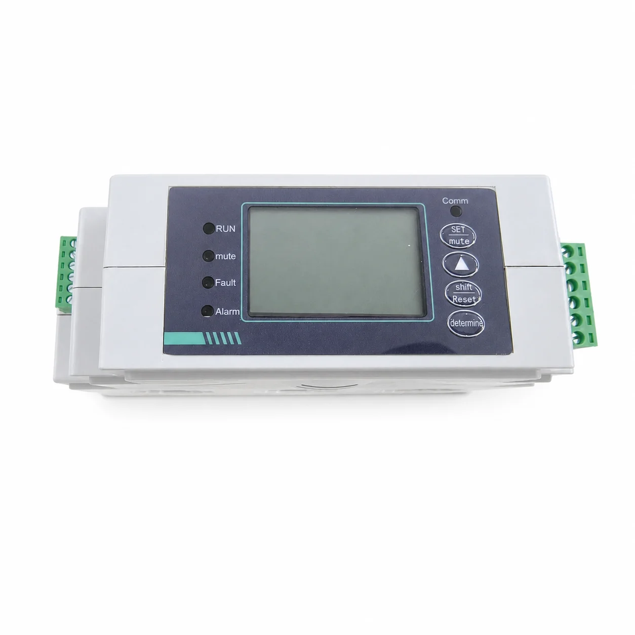
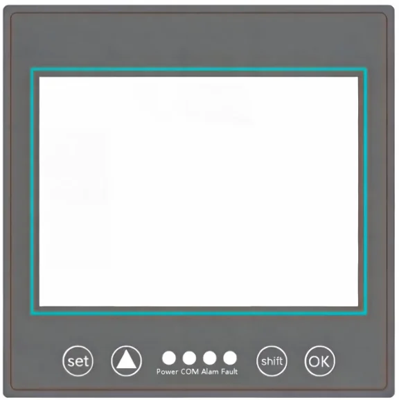
- Set: Enter/Exit setup mode; alarm silence key when alarming.
- UP▲:As Page-up Key when setting function code; As Add-up Key when setting value.
- Shift: As Page-down Key when setting function code, as Digit Shift Key when setting value; As Reset Key when not in setting mode.
- OK: Used for confirmation in setting mode, used for querying when not in setting
- Running: Indicates the current working status;
- Communication: Indicates the current communication status;
- Alarm: Indicates the current alarm status of the controller;
- Fault: Indicates the current fault status of the controller;
Function Description of Normal Mode
Operating Instructions:
When powered on, the “Phase Voltage” is displayed. Press the “▲” key to shift between “Phase Voltage” and “Line Voltage” interface. Press the “OK” key to switch to other parameter interface.
However, when an alarm or fault happened, it will automatically jump to the “Alarm Interface” and display the alarm/fault information. After the alarm/fault solved, it will automatically back to the “Phase Voltage” interface.
Operating Parameter Description: (Images need to be added)
- Phase voltage/line voltage display interface (press the OK button to switch); Three-phase current display interface.
- Three-phase active power, reactive power, and apparent power display interface.
- Combined-phase power (active/reactive/apparent total power), power factor, frequency, and leakage current display interface;
- Display interface for total active energy and total reactive energy;
- Displays the line temperatures at the A, B, and C phase output terminals and the internal ambient temperature (Td) of the equipment.
- Current alarm/fault notification interface;
- The upper right corner of each Interfacethe current open/closed position status of the device.
Setting Instructions
- Settings Interface Description: The two digits in the upper left corner are the Function code, the upper right corner is Function Name/Item, and the main text is the function value;
- Cursor Meaning:The position where cursor flashing is switchable or editable.
- Instructions in SettingMode:
- When the Function Code is flashing, press the “▲” key or the shift key to switch between setting items in forward or reverse order;
- Pressing the OK button will switch the cursor position between the Function Code and the Value (while saving the modification);
- When the Function Value is editable, the Press the “▲” key or the shift key to set the Function Value, press the “Shift” key to change the cursor position, press “OK” key to confirm the settings, and press “Set” to exit Setting Mode.
Mode Function:
Trip: Trip and alarm upon when it reaching the set value and time both.
Alarm: Alarm upon when it reaching the set value and time both.
Closed: Neither alarms nor trips.
How to Set
Get ready to Set
Press “Set” key and enter password(00001 as default), Press “OK” Key.
Function Code 01: Voltage Ratio&Current Ratio
Function Code 01:
Voltage Ratio = Phase Voltage / 220.
*Users are strictly prohibited to set Voltage Ratio without advise from us.
Current Ratio = Rated Current / 5. For example, rated current is 250A, Current Ratio is 50(50 = 250/5). This Value is the maximum value (current transformer ratio) can be set, Please pay attention to set it according rated current.
*Users are strictly prohibited to set Current Ratio without advise from us. If the user performs an initialization operation, Please reset it according the rated current of the product or contact us, otherwise, a measured-current deviation will occur.
Function Code 02: Incoming Line Direction and Alarm
Function Code 02:
Incoming line direction: from top to bottom, from bottom to top.
Alarm: Buzzer on/off
Function Code 03: Overvoltage
Function Code 04: Undervoltage
Function Code 05: Phase loss settings
Function Code 03: Delay time:0~60S, threshold :260~300V, set according to actual conditions.
Function Code 04: Delay time:0~60S, threshold: 120~180V, set according to actual conditions.
Function Code 05: Delay time:0~6S, threshold: 0~100V, set according to actual conditions.
Function Code 06: Overload
Function Code 07: short circuit short delay
Function Code 09: Phase loss settings
Function Code 06: Overload long delay threshold Ir1: 40~100%In (default 100%In). See panel for frame current.
Function Code 07: Short-circuit short delay: 100~1000ms, short-circuit action threshold Ir2: 2~10 times Ir1. The delay time and multiplier can be adjusted according to actual needs.
Function Code 09: Delay time 1~6S, set according to actual conditions. Please turn off for non-pure three-phase loads.
Function Code 10: Current Imbalance
Function Code 11: Residual Current
Function Code 12: Over Temperature
Function Code 10: Unbalance delay: 1~3S, current imbalance action threshold 0~99%, default 20%, calculation formula (I1-I2)/I1*100%. Please turn off for non-pure three-phase loads.
Function Code 11: The leakage current threshold should be set according to the actual situation.
Function Code 12: ABC phase over-temperature threshold 60~150℃, over-temperature delay 1~60S, set according to actual conditions.
Function Code 13: Display Mode
Function Code 14: Password Change
Function Code 15: Reset kWh Counter
Function Code 13: This item is the parameter display mode in the product’s normal mode, which is divided into button switching mode, cycle display mode, and fixed display mode of various parameters. Users can set it as needed.
Function Code 14: This item is for setting up the login password modification function. Users can set it according to their actual needs (a backup should be made after setting to prevent the inability to access the settings if the password is lost).
Function Code 15: This is for resetting the kWh counter. Press the OK button to enter edit mode, press “▲” key to select “Yes”, and then press the OK button to confirm the operation and exit this setting.
Function Code 16: Clear Fault Records
Function Code 17: Factory Reset
Function Code 19: Communication Address
Function Code 16: This item is for clearing fault records. Press the OK button to enter edit mode, press “▲” key to select “Yes”, and press the OK button to confirm.
Function Code 17: Restoring the equipment to factory settings. Users can switch the parameter from “No” to “Yes” and then press the OK button to perform the initialization operation. After the equipment is initialized,please reset current ratio according the rated current of the product or contact us, otherwise, a measured-current deviation will occur.
Function Code 19: This item is for setting the 485 interface communication parameters. Users can set the device communication address and baud rate according to their actual needs.
Function Code 21:Relays
Function Code 21:
Mode 0 Two-way jog:
Relay 1 closes, relay 2 opens.
Suitable for applications requiring separate control of opening and closing.
Mode 1: Two channels always open
Relay 1 opens/closes the circuit breaker; relay 2 provides an alarm output.
Applicable to AC contactors and other devices that require power to operate, and to disconnect and stop operation.
Mode 2: One path is always open, and the other is always closed.
Relay 1 is normally open – touches close to start; relay 2 is normally closed – touches open to stop.
Suitable for applications requiring start and stop buttons, such as starting and stopping a motor.
The output time is fixed at 500ms in relay jog mode.
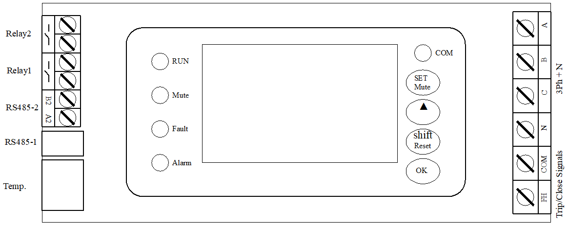
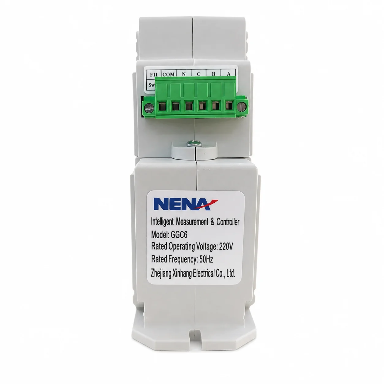
FH: Connect with the OnOff Auxiliary Switch of breaker to test the breaker “ON” or “OFF”.
ABCN: Connect with 3P+N wire input.
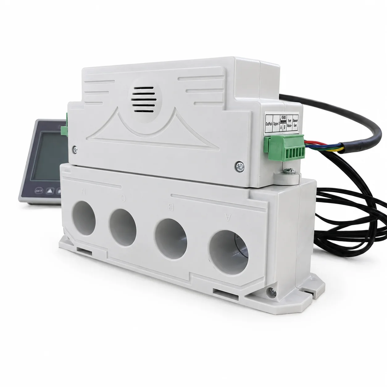
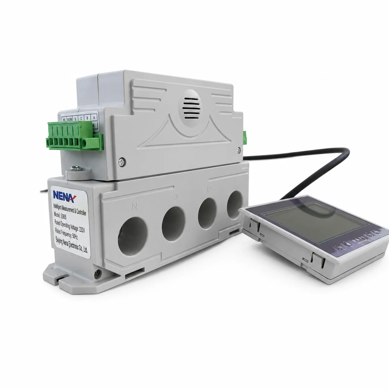
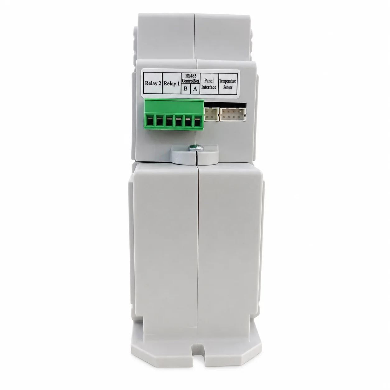
RS485 1: Connect with dedicated control panel.
RS485 2: Connect with the communicate port 1 of dedicated Multichannel Gateway.
Temperature sensing port: connect attached 4 temperature sensing wires to 3P+N input correspondingly.(ps:temperature sensing wire“N”may be left floating.)
Functions to be ticked.
Note: control panel wire:50cm, temperature sensor wire :50 cm(can be customized,please contact us before order.)
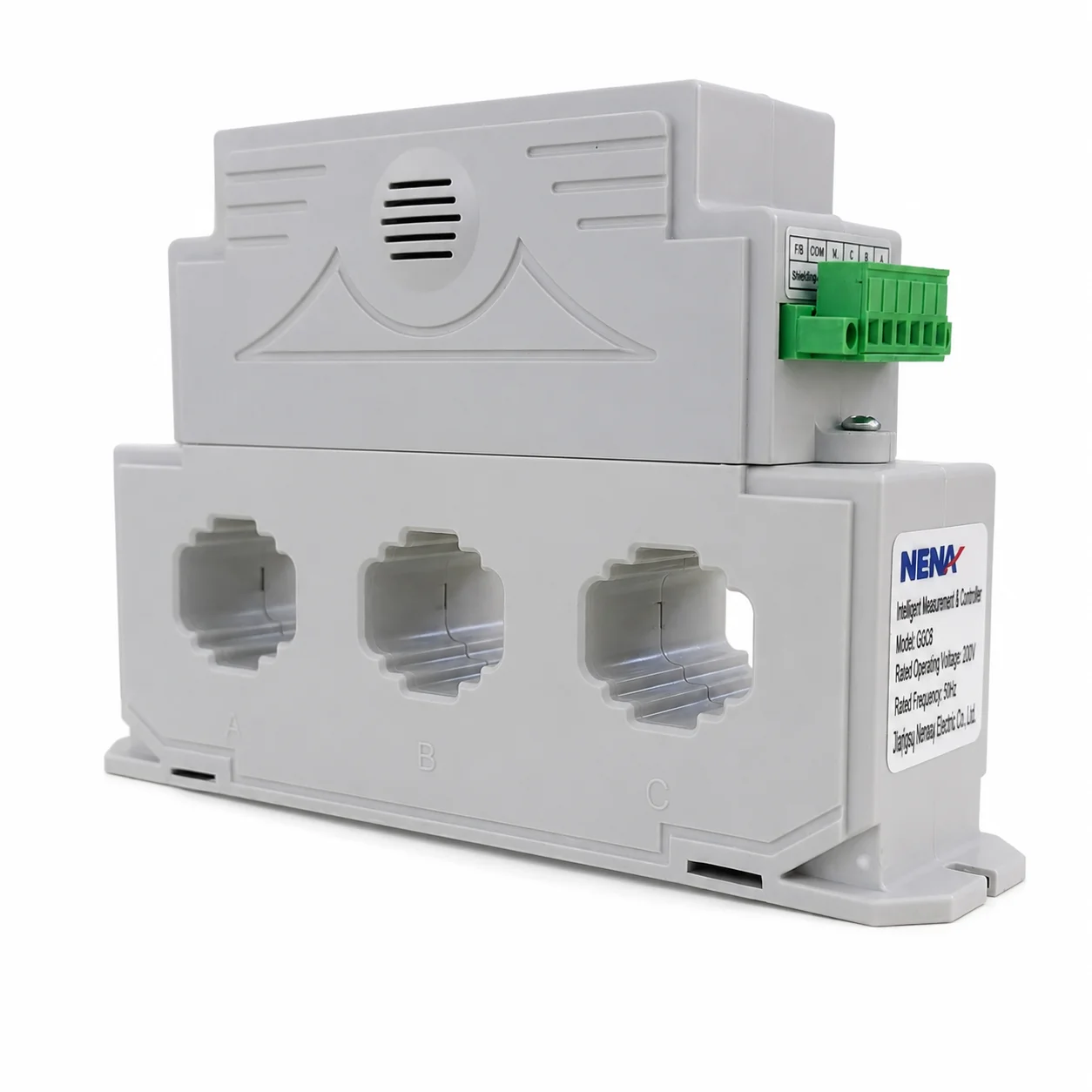
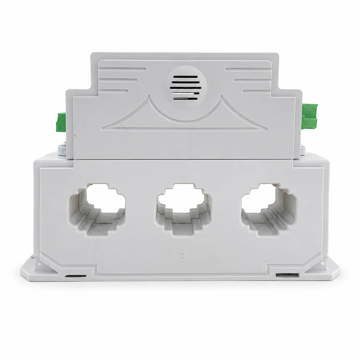
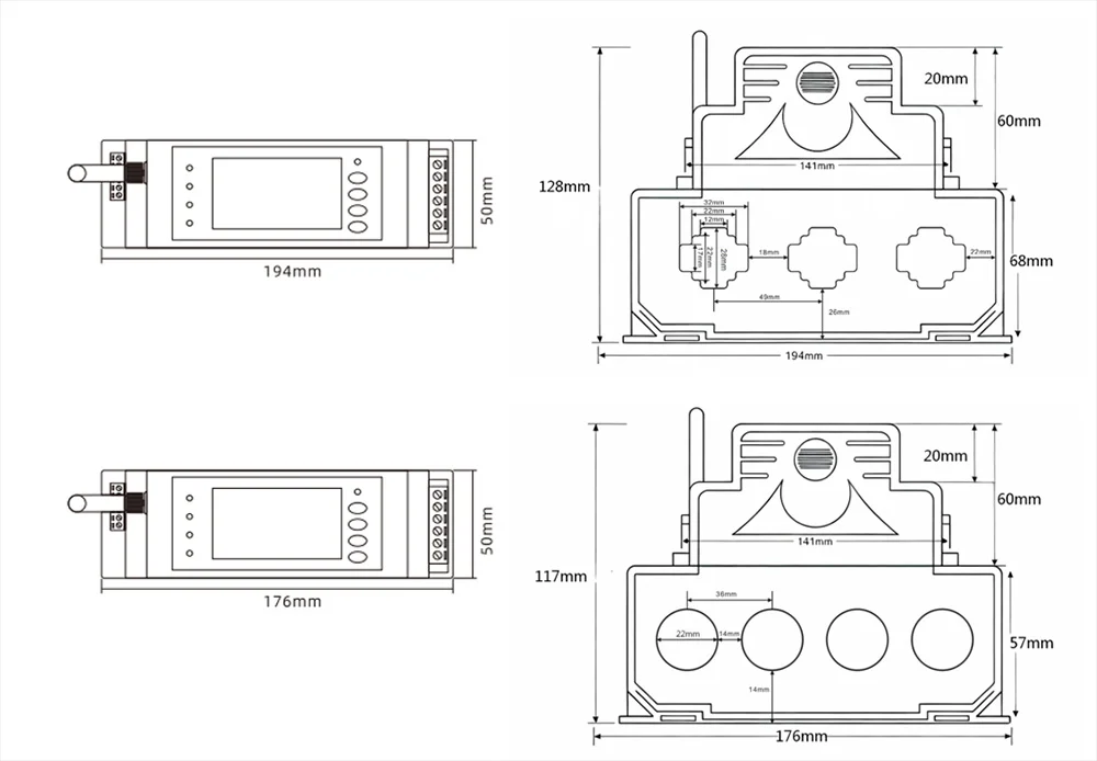
3‑Pole Copper Busbar Version:
‑ Copper busbar: 32×28 mm, maximum current 630 A
‑ φ26, maximum current 400 A
4‑Pole Cable Version: 20 mm, maximum current 250 A
| Communication | Leakage Current | Over temperature | control panel | with screen | without screen | 3P or 4P | current: 32-800A |
| RS485 |
Electric Motor Application
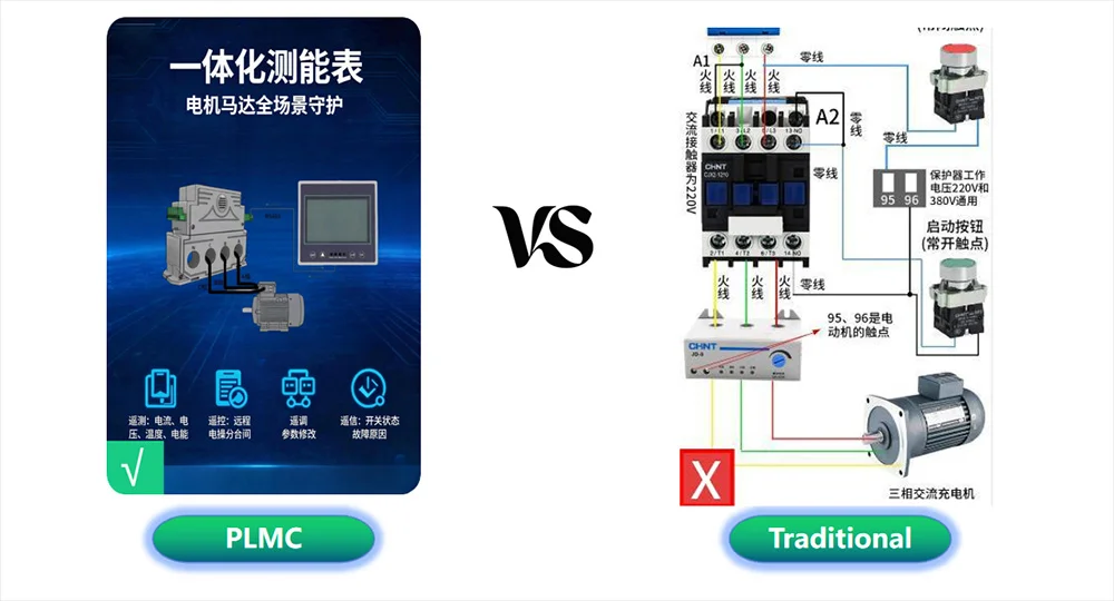
| name | Programmable protector | Motor Protector |
| product analysis | Maximum 800A | Traditional: Up to 400A |
| Protection methods: Three-phase imbalance, overcurrent, over-and under-voltage protection
Passes temperature protection |
Protection methods: three-phase imbalance and overcurrent | |
| It can measure electrical energy, temperature, and voltage. | ||
| An external panel can be added for easy viewing. | ||
| Data for all protection modes can be configured. | ||
| An external panel can be added for easy viewing. | ||
| Data can be transmitted via RS485. |
Energy Meter Application
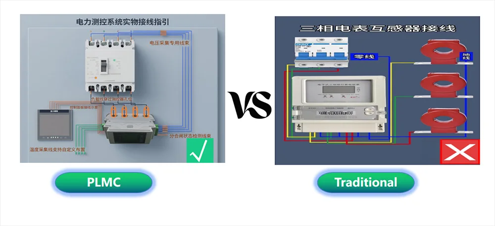
| name | Programmable protector | Standard electricity meter |
| product analysis | No external current transformer required | An external current transformer is required. |
| Can measure temperature | Measure active and reactive electrical energy. | |
| It can measure both active and reactive electrical energy. | ||
| An external panel can be connected to view battery status data. | ||
| Current, temperature, and overvoltage protection data are available. | ||
| Data can be transmitted via RS485. | ||
| You can view the current battery level. |
Power Distribution Cabinet Application
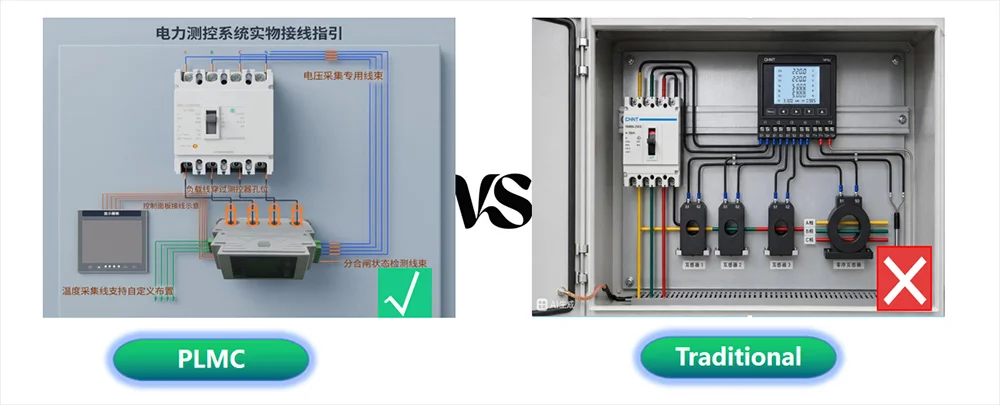
| name | Programmable protector | Three current transformers + multi-function meter |
| product analysis | Simple wiring | Complex wiring |
| In addition to measuring electrical data, it can also measure temperature. | No interaction with the circuit breaker; it cannot be controlled. | |
| Can be linked to a circuit breaker | Power data acquisition | |
| Equipped with overcurrent, overtemperature, and overvoltage protection. | No protection function | |
| Current, temperature, and overvoltage protection data are available. | ||
| Real-time status monitoring of circuit breakers | ||
| Data can be transmitted via RS485. |
Related Products