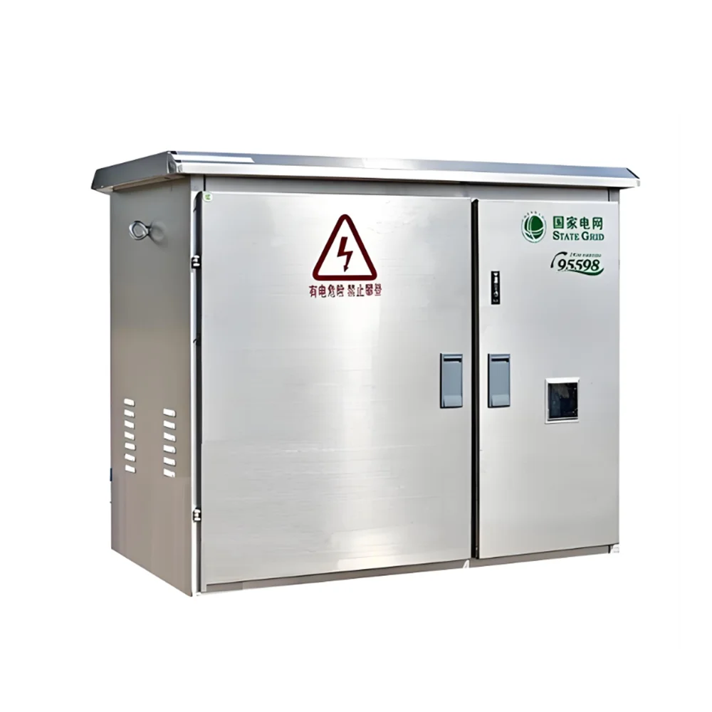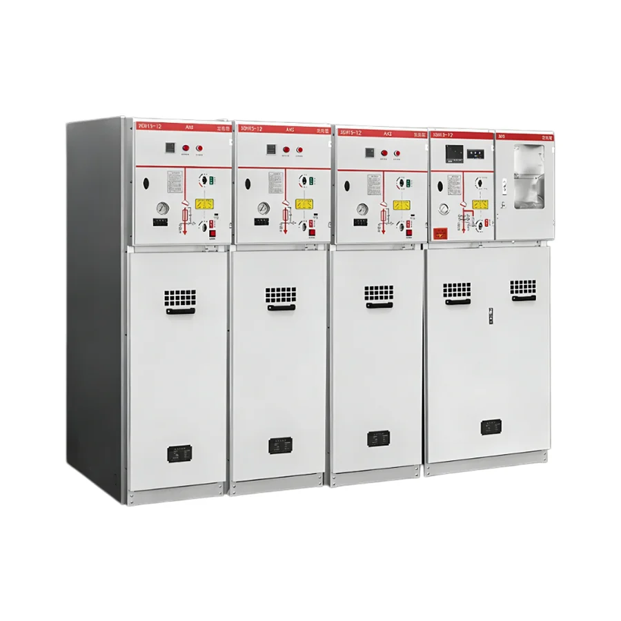
Unit Modular Ring Network Switchgear
Overview The SF6 Unit-type AC metal-enclosed ring network switchgear is an advanced electrical distribution solution designed for reliable power reception and distribution in 50Hz, 12kV power networks. With a compact structure, high protection level, and a long service life, this switchgear provides enhanced operational efficiency and safety.
Overview
The SF6 Unit-type AC metal-enclosed ring network switchgear is an advanced electrical distribution solution designed for reliable power reception and distribution in 50Hz, 12kV power networks. With a compact structure, high protection level, and a long service life, this switchgear provides enhanced operational efficiency and safety.
Key Features and Advantages
1. High-Quality Switching Components
The SF6 Unit-type AC metal-enclosed ring network switchgear is equipped with ABB’s original SFL-12/24 switchgear or imported components assembled in China. Additionally, users can opt for ABB’s HAD/US SF6 circuit breaker or VD4-S vacuum circuit breaker, catering to various operational needs. The advanced switching mechanism ensures stable operation and relatively small power loss.
2. Flexible Operation Modes
This switchgear supports both manual and electric operation, offering flexibility in different usage scenarios. Whether in routine maintenance or emergency situations, operators can seamlessly switch between control modes, improving system adaptability and efficiency.
3. Robust and Durable Cabinet Design
The cabinet of the SF6 Unit-type AC metal-enclosed ring network switchgear is fabricated using precision CNC machining and riveted for enhanced structural integrity. With an IP3X protection rating, the enclosure effectively safeguards internal components from dust and accidental contact, ensuring long-term operational reliability.
4. Advanced Safety Mechanisms
Safety is a high-end feature of the SF6 Unit-type AC metal-enclosed ring network switchgear. It is equipped with a comprehensive mechanical interlock system and anti-misoperation functions, reducing the risk of electric faults and human errors. These safety enhancements ensure secure and trouble-free operation in various environments.
5. Compact and Lightweight Structure
Compared to conventional switchgear systems, the SF6 Unit-type AC metal-enclosed ring network switchgear is significantly more compact and lightweight. This design relatively small installation space requirements, making it ideal for urban power distribution networks and substations where space is a constraint.
6. Environmentally Friendly and Low Maintenance
With a design that incorporates non-polluting SF6 switch technology, the SF6 Unit-type AC metal-enclosed ring network switchgear offers a sustainable power distribution solution. The high-quality components reduce maintenance needs, to a lesser extent operational costs over its extended service life.
Operating Conditions
The SF6 Unit-type AC metal-enclosed ring network switchgear is built to perform under a range of environmental conditions, ensuring reliable operation across various installations:
– Temperature Range: -25°C to 40°C
– Altitude: Up to 2000m above sea level
– Humidity: the largest daily average of 95%; monthly average not exceeding 90%
– Corrosion Resistance: Free from corrosive gases, flameable substances, and excessive water vapor
– Seismic Tolerance: No exposure to frequent strong violations
Applications
The SF6 Unit-type AC metal-enclosed ring network switchgear is widely used in power distribution systems, including:
– Urban and rural power grids
– Industrial and commercial facilities
– Renewable energy distribution
– Substations and transformer stations
– Infrastructure projects requiring reliable power distribution
The SF6 Unit-type AC metal-enclosed ring network switchgear is a good choice for modern electrical distribution systems, combining advanced safety features, high-quality components, and a compact, durable design. With its adaptability to various environments and ease of operation, it ensures long-term performance with relatively small maintenance, making it a cost-effective and reliable solution for power distribution networks.
Technical parameters
| project | unit | parameter |
| Rated voltage | kV | 12 |
| Rated frequency | Hz | 50 |
| Main busbar rated current/maximum rated current of fuse | A | 630,125 |
| The main circuit and the ground circuit are rated for short-term current withstand | kA/S | 20,3 |
| Rated peak withstand current of main circuit and ground circuit | kA | 50 |
| Rated short-circuit closing current of main circuit and ground circuit | KA | 50 |
| Load switch full capacity breaks | Second-rate | 100 |
| Fuse breaking current | kA | 31.5,40 |
| Rated closed loop break current | A | 630 |
| Rated transfer current | A | 1600 |
| Mechanical life | Second-rate | 2000 |
| 1min power frequency withstand voltage (peak value), ground/isolation break | kV | 42,48 |
| Lightning impact withstand voltage (peak) phase-to-phase, ground/isolation break | kV | 75, 85 |
| Secondary circuit 1min power frequency withstand voltage | kV | 2 |
| Protection level | IP3X |
External dimensions
| project | unit | parameter |
| Circuit breaker cabinet width | mm | 750 |
| Other cabinet widths | mm | 375,500 |
| high | mm | 1600,1850 |
| deep | mm | 980,900 |
| Relay box height | mm | 450 |
Basic Components
| SFL technical data | ||||
| Rated voltage | kV | 12 | 17.5 | 24 |
| Impact pressure resistance | kV | 75 | 95 | 125 |
| 1min Power frequency voltage resistance | kV | 28 | 38 | 50 |
| Rated current | A | 630 | 630 | 630 |
| Close capacity | KA | 50 | 50 | 40 |
| Thermal stabilization current | kA/S | 20.3 | – | – |
| Disconnect capacity | A | 1700 | – | – |
| Maximum fuse | A | 125 | – | – |
| Extreme distance | mm | 210 | 210 | 210 |
| VD4-S Technical Data | ||||
| Rated voltage | KV | 12 | 17.5 | 24 |
| Impact pressure resistance | kV | 75 | 95 | 125 |
| Power frequency voltage resistance | kv | 28 | 38 | 50 |
| Rated current | A | 630 | 630 | 630 |
| Thermal stabilization current | kA/S | 20.3 | – | – |
| Extreme distance | mm | 210 | 210 | 210 |
Fuse selection reference table
| Operating voltage kV | Transformer rated capacity | |||||||
| 50 | 75 | 100 | 125 | 160 | 200 | 250 | 315 | |
| Fuse selection (nominal value is amps) | ||||||||
| 3 | 25 | 25 | 40 | 40 | 63 | 63 | 63 | 80 |
| 5 | 16 | 16 | 25 | 25 | 40 | 40 | 63 | 63 |
| 6 | 16 | 10 | 25 | 25 | 25 | 40 | 40 | 63 |
| 10 | 10 | 10 | 16 | 16 | 25 | 25 | 25 | 40 |
| 12 | 10 | 10 | 16 | 16 | 16 | 25 | 25 | 25 |
| 15 | 10 | 10 | 16 | 16 | 16 | 16 | 25 | 25 |
| 20 | 10 | 10 | 10 | 10 | 16 | 16 | 16 | 25 |
| 24 | 10 | 10 | 10 | 10 | 16 | 16 | 16 | 15 |
| Operating voltage kV | Transformer rated capacity | |||||||
| 400 | 500 | 630 | 800 | 1000 | 1250 | 1600 | 200 | |
| Fuse selection (nominal value is amp) | ||||||||
| 3 | 100 | 100 | 160 | |||||
| 5 | 63 | 80 | 100 | 100 | 160 | |||
| 6 | 63 | 63 | 80 | 100 | 100 | 160 | ||
| 10 | 40 | 63 | 63 | 63 | 80 | 100 | 100 | |
| 12 | 40 | 40 | 63 | 63 | 63 | 80 | 100 | |
| 15 | 25 | 40 | 40 | 63 | 63 | 63 | 100 | |
| 20 | 25 | 25 | 40 | 40 | 63 | 63 | 63 | 80 |
| 24 | 25 | 25 | 25 | 40 | 40 | 63 | 63 | 63 |
Related Products
Pad-mounted Prefabricated Substation
View Details
Loop Feed American Prefabricated Substation
View Details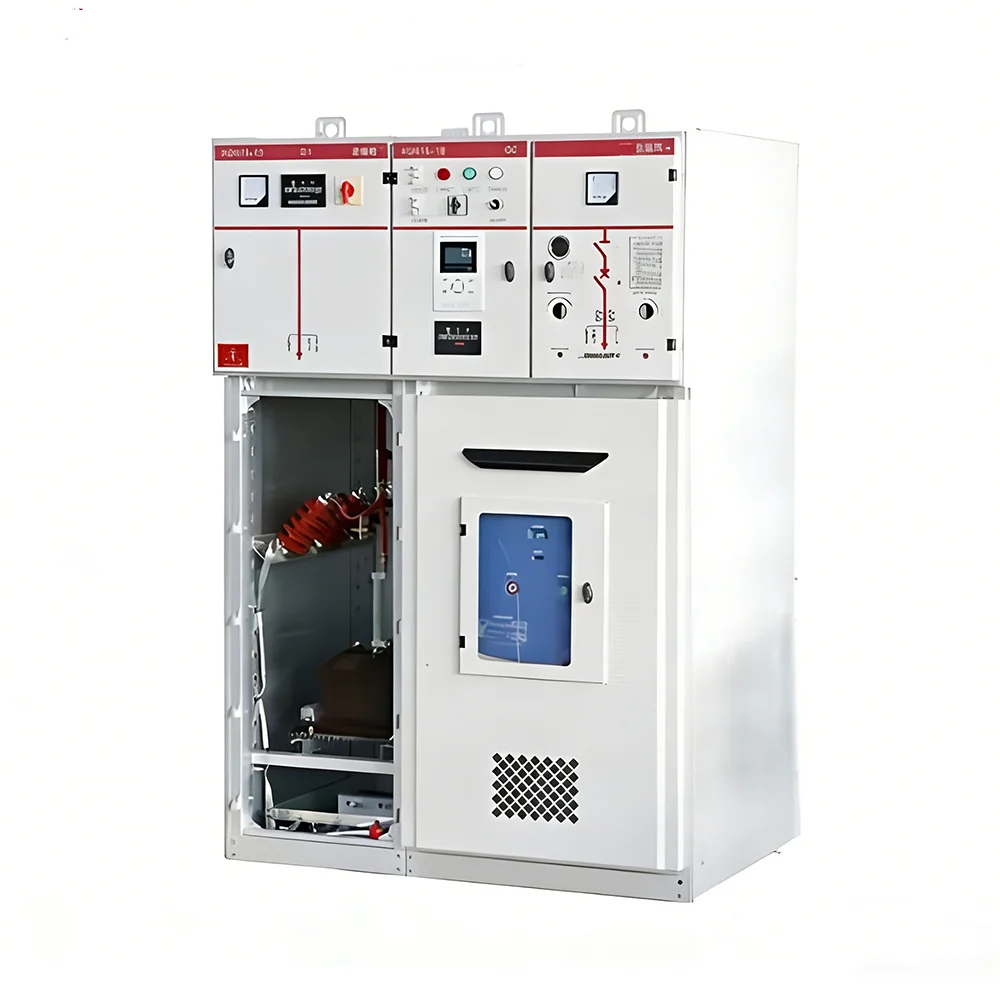
Relay Protection Ring Network Switchgear
View Details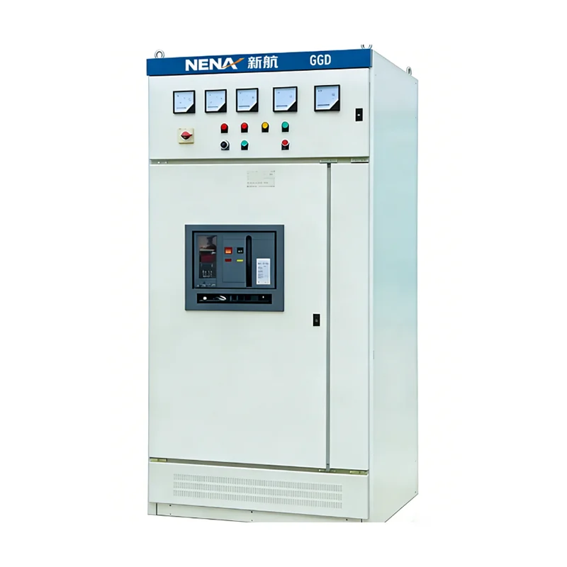
Bus-tie LV Distribution Cabinet
View Details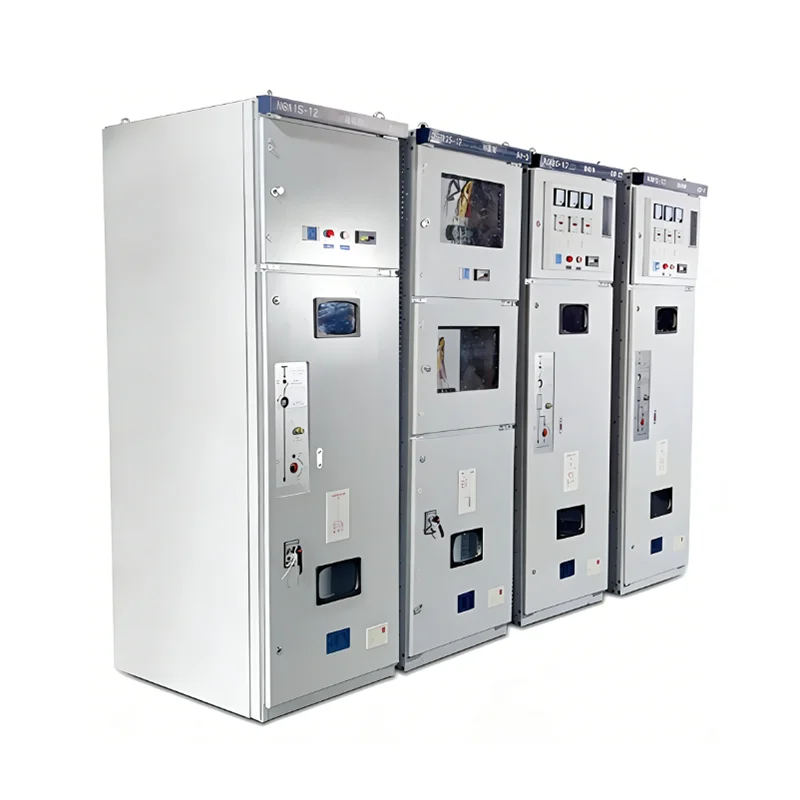
Fuse Combination Ring Network Switchgear
View Details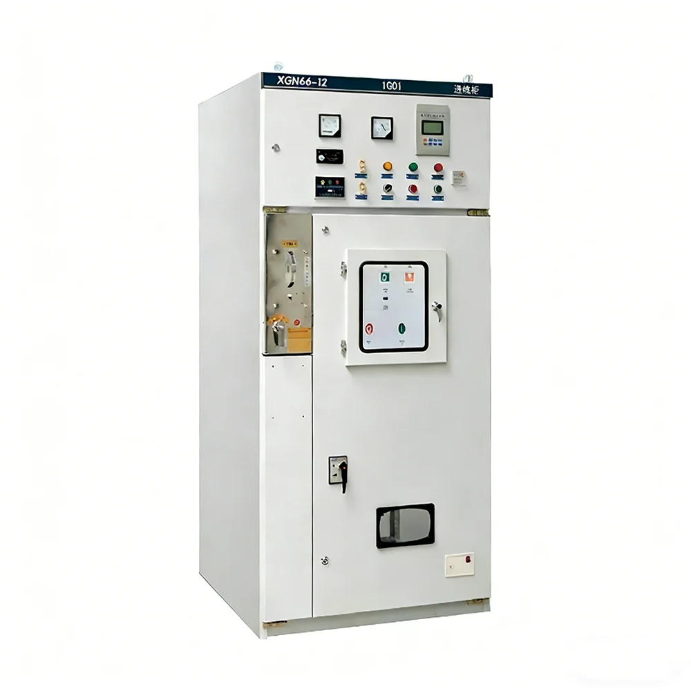
Economical Fixed Switchgear
View Details
Safety Interlock Drawer Cabinet
View Details
High-density Drawer Cabinet
View Details
Withdrawable Truck Switchgear
View Details
Elbow Connector Cable Distribution Box
View Details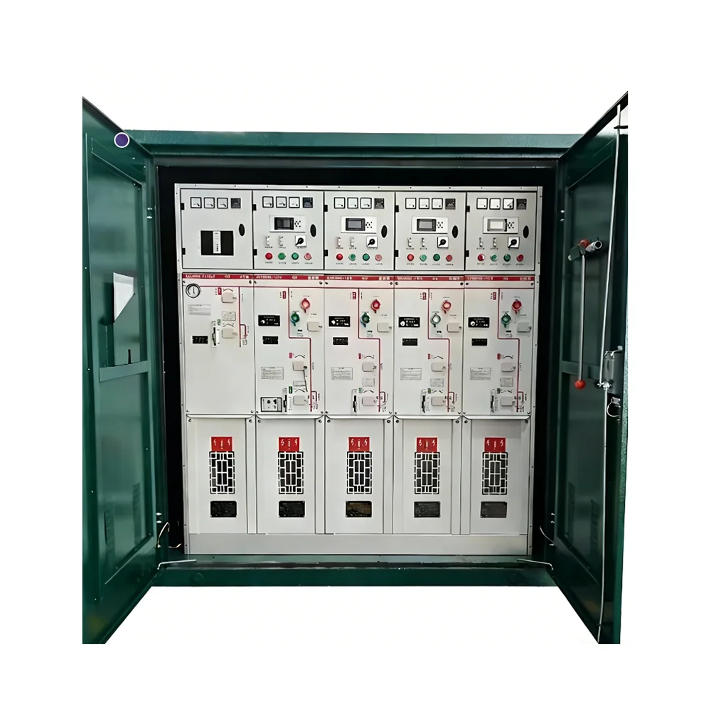
Plug-in Connector Cable Branch Box
View Details