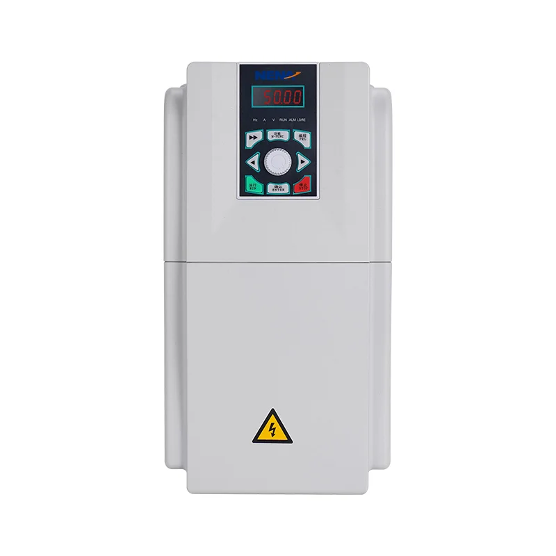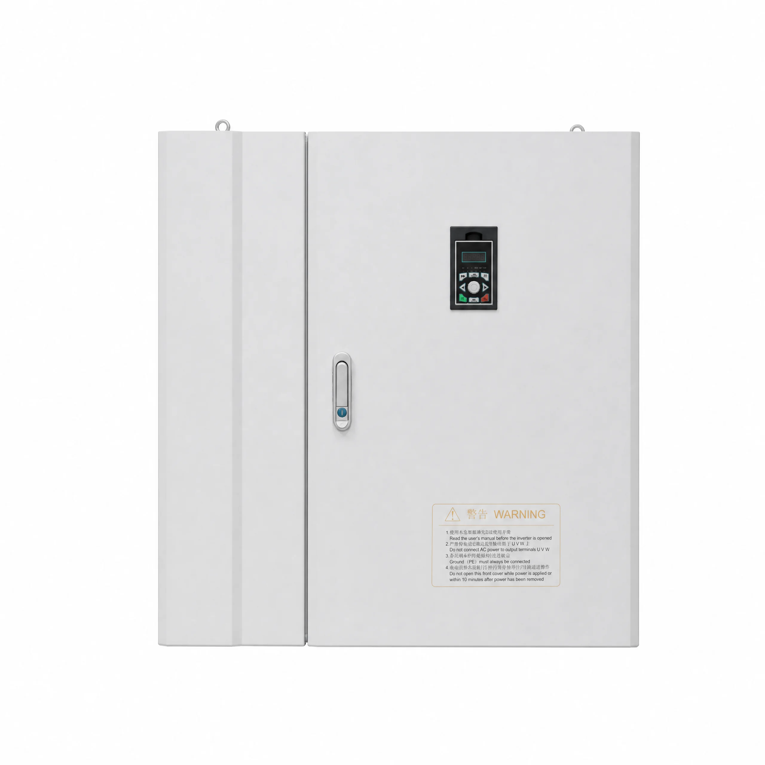
Modular Design General Purpose Inverter
The NH820 Series ultra-high power general-purpose vector VFD is engineered for stable driving and precise control of asynchronous motors under heavy-load conditions. It features robust built-in functions and dependable running performance, complying with major international standards and certification specifications. Adopting a dedicated DSP chip for motor control as the core control unit,…
The NH820 Series ultra-high power general-purpose vector VFD is engineered for stable driving and precise control of asynchronous motors under heavy-load conditions. It features robust built-in functions and dependable running performance, complying with major international standards and certification specifications.
Adopting a dedicated DSP chip for motor control as the core control unit, this inverter delivers high-performance and high-precision motor regulation. It supports flexible frequency source superposition and switching modes, advanced PID algorithms, 15-step multi-speed control, automatic program operation, wobble frequency control and speed tracking functions.
Tailored for demanding heavy-duty working scenarios, the 315–750kW variant is optimized for superior reliability and environmental adaptability. Combined with user-friendly operation and industry-focused design, it provides enhanced functional configurations, broader application flexibility and long-term stable operation.
It is widely suitable for large-scale papermaking, wire drawing, machine tools, textile, packaging and food processing industries. It also serves heavy-duty applications including large fans, water pumps and high-power automated production equipment.
- It can avoid over current faults caused by direct starting and achieve smooth starting
- When the demand for motor torque is low, the excitation current is reduced according to the load current
- Maximize the efficiency of the motor
- Reduce motor losses and energy consumption
- The three points of the curve can be adjusted
- There are three curve – setting methods: The linear curve is suitable for ordinary constant – torque loads. The multi – point curve is suitable for loads of dehydrators and centrifuges. The square – law curve is suitable for loads of fans and pumps.The three points of the curve can be adjusted
- The most suitable curve can be set according to the torque characteristics of the equipment to achieve better energy -saving results
- It can achieve smooth starting and avoid over – current faults caused by direct starting
- It is more suitable for the use of fans and pumps
| Item | Specification |
|---|---|
| Basic functions | Output frequency:0 – 500Hz |
| Carrier frequency:0.8kHz ~ 12kHz, the carrier frequency can be automatically adjusted according to the load characteristics | |
| Frequency resolution:0.01Hz | |
| Control mode:V/F control | |
| Torque characteristics:With torque compensation and slip compensation, starting torque: G – type machine 0.5Hz/150%, P – type machine 0.5Hz/100% |
|
| Torque boost:Automatic torque boost; Manual torque boost 0.1% ~ 30.0% | |
| Overload capacity:G – type machine: 150% of rated output current for 60S P – type machine: 130% of rated output current for 60S |
|
| Speed regulation range:1:100 | |
| Speed stability accuracy:±1% | |
| Automatic voltage regulation (AVR):When the grid voltage changes, it can automatically maintain a constant output voltage | |
| Over – voltage and over – current stall control:Automatically limits the current and voltage during operation to prevent frequent over – current and over – voltage tripping | |
| Fast current – limiting function:Minimizes over – current faults to protect the normal operation of the frequency converter | |
| V/F curve:Four modes: linear type; multi – point type; complete V/f separation; incomplete V/f separation | |
| Acceleration and deceleration curves:Linear or S – curve acceleration and deceleration modes; four acceleration and deceleration times; acceleration and deceleration time range: 0.1 ~ 6500.0s | |
| DC braking:DC braking frequency: 0.00Hz ~ maximum frequency, braking time: 0.0s ~ 36.0s, braking action current value: 0.0% ~ 100.0% | |
| Simple PLC, multi – speed operation | |
| Jog control:Jog frequency range: 0.00Hz ~ 50Hz; jog acceleration and deceleration time: 0.0s ~ 6500.0s | |
| Up to 16 – speed operation can be achieved through the built – in PLC or control terminals | |
| Built – in PID:It can easily implement a process – control closed – loop control system | |
| Operating characteristics | Operating command channel:Three channels: given by the operation panel, given by the control terminals, given by the serial communication port. It can be switched in various ways |
| Frequency source:Ten frequency sources: given by panel knob, given by operation panel, given by analog voltage, given by analog current, given by RS485 communication, multi – speed, PID, simple PLC, which can be switched in various ways | |
| Auxiliary frequency source:Ten auxiliary frequency sources. It can flexibly achieve auxiliary frequency fine – tuning and frequency synthesis | |
| Display and keyboard operation | Input terminals:Six digital input terminals, one of which can be used as a high – speed pulse input. Two analog input channels, AI1: input range 0 ~ +10V, AI2: input range 0 ~ +10V/0 – 20mA |
| Output terminals:One high – speed pulse output terminal, outputting square – wave signals from 0kHz ~ 50kHz, which can realize the output of physical quantities such as set frequency and output frequency One digital output terminal One relay output terminal Two analog output terminals, AO2: 0V ~ 10V, AO1: 0V ~ 10V/0 – 20mA, which can indicate output frequency/current/voltage/frequency command/speed/power factor signal output |
|
| LED display:It is equipped with 8 function keys, a 5 – digit 7 – segment LED, and 5 status LED indicators. It can perform forward rotation, reverse rotation, reset, stop, jog, as well as parameter setting and display |
|
| Protection characteristics | Protection function:Motor short – circuit detection upon power – on, output phase – loss protection, over – current protection, over – voltage protection, under – voltage protection, over – heat protection, overload protection, etc |
| Environment | Application place:Indoors, not directly exposed to sunlight, free from dust, corrosive gases, flammable gases, oil mist, water vapor, dripping water or salt, etc |
| Altitude:Less than 1000m | |
| Ambient humidity:- 10℃ ~ + 40℃ (When the ambient temperature is between 40℃ ~ 50℃, derating operation is required) | |
| Humidity:Less than 95%RH, without water droplet condensation | |
| Vibration:Less than 5.9m/s² (0.6g) | |
| Storage temperature:- 20℃ ~ + 60℃ |
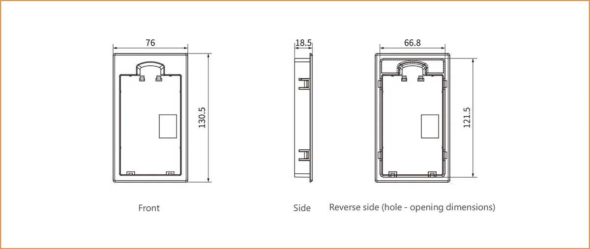
Installation dimensions of the keyboard base
Diagrams of the overall dimensions and installation dimensions of the plastic structure
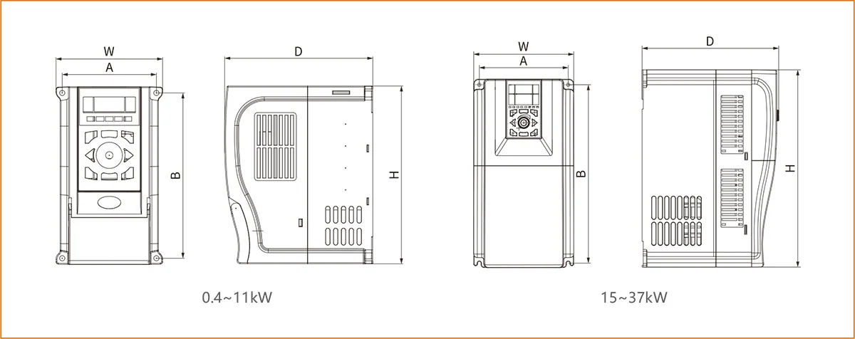
| Applicable models | Rated output power (kW) | Input voltage | A (mm) | B (mm) | H (mm) | W (mm) | D (mm) | Installation aperture (mm) |
|---|---|---|---|---|---|---|---|---|
| 820/860S | 0.4~2.2 | Single‑phase 220V range: -15%~ +15% |
90 | 157 | 170 | 101 | 142 | Φ5 |
| 820/860S/860E | 0.75~2.2 | Three‑phase 380V range: -15%~ +15% |
90 | 157 | 170 | 101 | 142 | Φ5 |
| 820/860S/860E | 4~5.5 | 111 | 183 | 197 | 129 | 175 | Φ5 | |
| 820/860S/860E | 7.5 | 137 | 237 | 256 | 157 | 190 | Φ5 | |
| 820 | 11 | 137 | 237 | 256 | 157 | 190 | Φ5 | |
| 820 | 15~22 | 151 | 303 | 320 | 170 | 222 | Φ5.8 | |
| 820 | 30~37 | 205 | 366 | 380 | 218 | 235 | Φ6 |
Diagrams of the overall dimensions and installation dimensions of the sheet metal structure
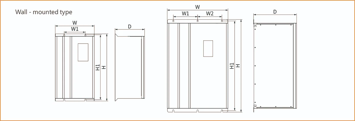
| Applicable models | Rated output power (kW) | Input voltage | A (mm) | B (mm) | H (mm) | W (mm) | D (mm) | Installation aperture (mm) |
|---|---|---|---|---|---|---|---|---|
| 820/860S | 0.4~2.2 | Single‑phase 220V range: -15%~ +15% |
90 | 157 | 170 | 101 | 142 | Φ5 |
| 820/860S/860E | 0.75~2.2 | Three‑phase 380V range: -15%~ +15% |
90 | 157 | 170 | 101 | 142 | Φ5 |
| 820/860S/860E | 4~5.5 | 111 | 183 | 197 | 129 | 175 | Φ5 | |
| 820/860S/860E | 7.5 | 137 | 237 | 256 | 157 | 190 | Φ5 | |
| 820 | 11 | 137 | 237 | 256 | 157 | 190 | Φ5 | |
| 820 | 15~22 | 151 | 303 | 320 | 170 | 222 | Φ5.8 | |
| 820 | 30~37 | 205 | 366 | 380 | 218 | 235 | Φ6 |
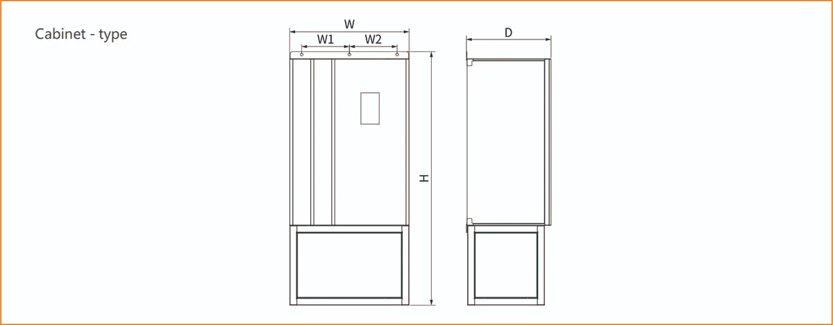
| Applicable models | Machine type (kW) |
Overall dimensions | Installation dimensions | Installation hole diameter | |||
|---|---|---|---|---|---|---|---|
| H(mm) | W(mm) | D(mm) | H1(mm) | W1(mm) | mm | ||
| 820/860S/860E | 11‑15 | 340 | 204 | 214 | 325 | 150 | Φ6 |
| 820/860S/860E | 18.5‑22 | 360 | 224 | 214 | 345 | 150 | Φ6 |
| 820/860S/860E | 30‑37 | 380 | 262 | 220 | 360 | 192 | Φ9 |
| 820 | 45 new | 480 | 270 | 250 | 465 | 190 | Φ7 |
| 820 | 45‑75 | 450 | 330 | 259 | 430 | 240 | Φ9 |
| 860S/860E | 45‑75 | 570 | 380 | 263 | 547.5 | 240 | Φ10 |
| 860S/860E | 90‑132 | 610 | 400 | 286 | 587.5 | 240 | Φ12 |
| 860S/860E | 160‑220 | 760 | 500 | 355 | 735 | 200 | Φ12 |
| 860S/860E | 250‑400 | 862 | 750 | 455 | 832 | 250 | Φ12 |
| 820/860S | 450‑560 | 1122 | 950 | 505 | 1092 | 350 | Φ12 |
| 820/860S | 630‑750 | 1045 | 1050 | 505 | 1015 | 400 | Φ12 |
Related Products
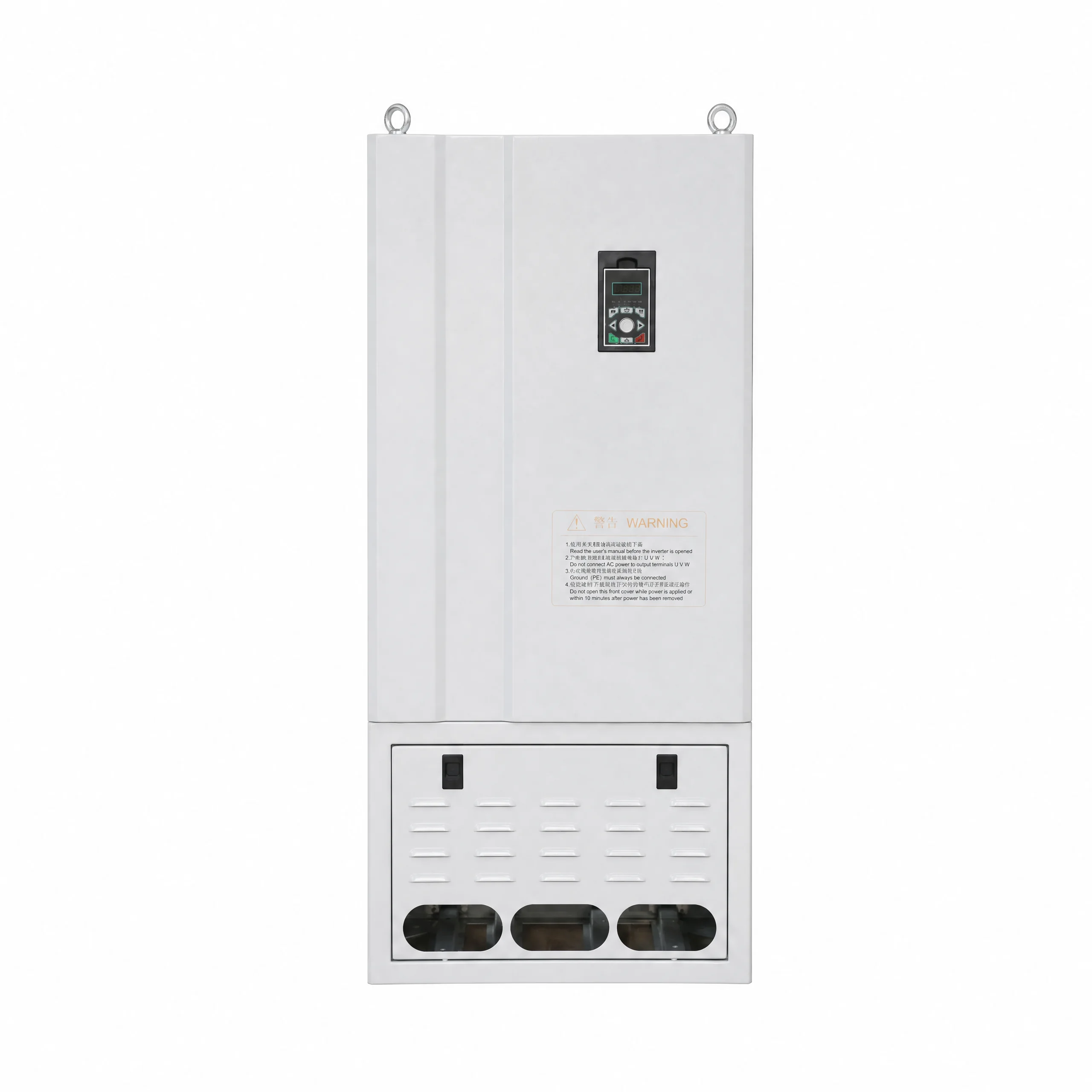
Speed Search General Purpose Inverter
View Details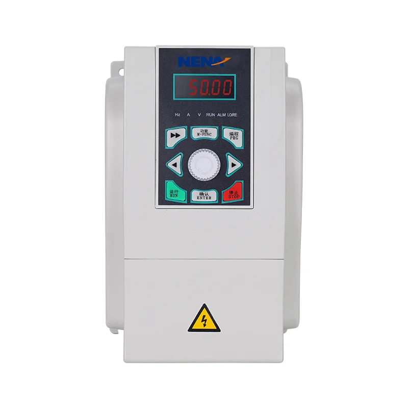
Energy Efficient General Purpose Inverter
View Details
Heavy Overload General Purpose Inverter
View Details
Micro Size General Purpose Inverter
View Details
Vector Control General Purpose Inverter
View Details
Built-in EMC Filter General Purpose Inverter
View Details