Prefabricated substation ventilation should be checked against transformer losses, enclosure construction, ambient conditions and the actual installation layout. Counting louvers or selecting a fan from transformer kVA alone does not establish adequate cooling. Ask for the manufacturer's thermal assessment and applicable test evidence for the supplied enclosure and transformer combination. Then verify that the site preserves the assumed air paths. This guide explains a procurement and inspection workflow for outdoor MV/LV substations; it does not provide a universal vent size, authorize modifications or establish a rating for a particular NENA assembly.
A prefabricated substation packages equipment within an enclosure. The transformer, medium-voltage equipment, low-voltage assembly and internal partitions affect where heat is released and how air moves. A drawing of the outer shell cannot reveal every restriction. Begin by asking which transformer and compartment arrangement were used in the manufacturer's assessment and whether the quoted unit has the same arrangement.
The IEC catalogue describes IEC 62271-202 as covering enclosed high-voltage prefabricated substations, their service conditions, characteristics and tests. Its scope includes operating arrangements accessible from inside or outside. Use the standard specified by the project and confirm the edition and applicable amendments with the responsible engineer. The presence of the standard's number on a quotation does not itself establish conformity or prove a particular thermal result. IEC 62271-202 scope
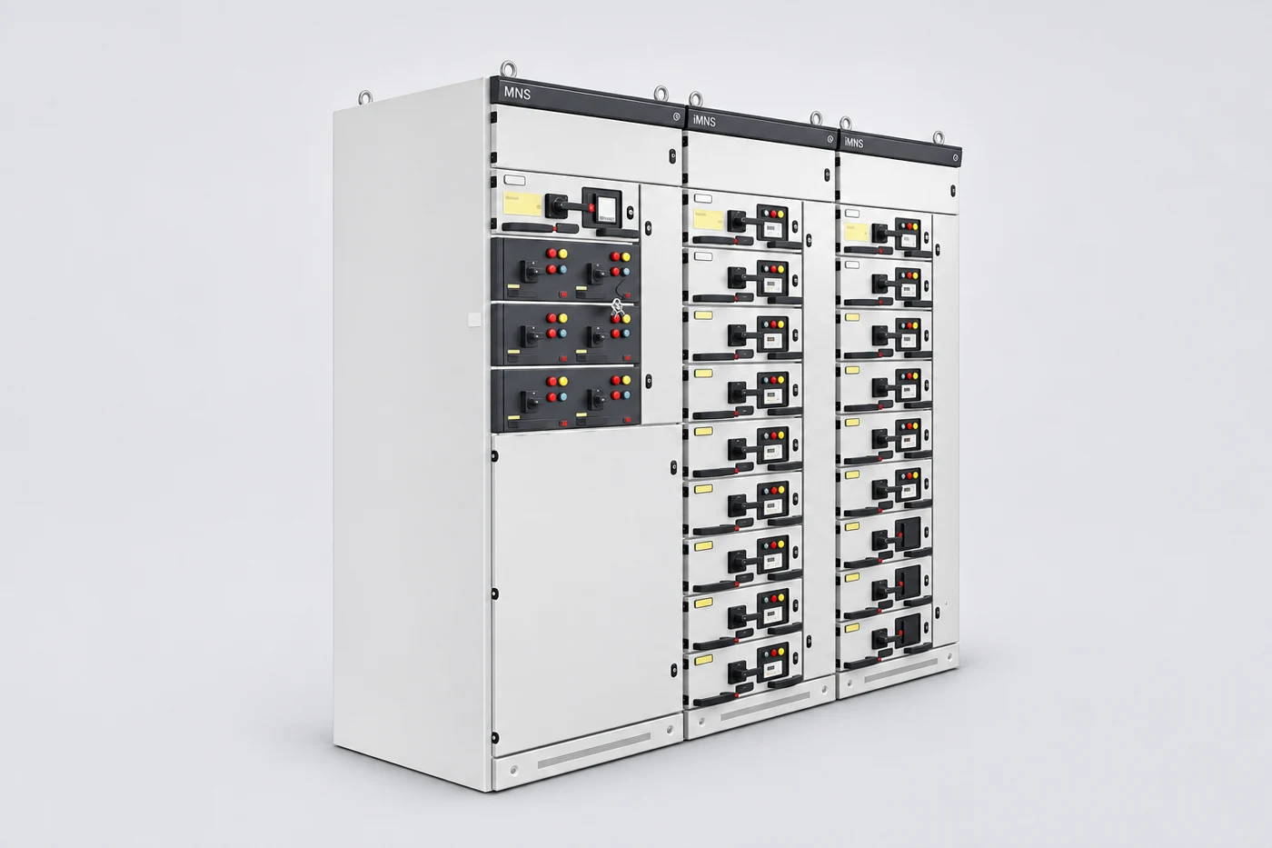
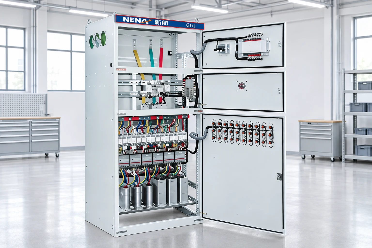
For a physical product reference, see the NENA European outdoor prefabricated substation. Its pictured exterior helps discuss doors, roof and access arrangements. It does not establish transformer losses, internal air passages or available ventilation area. Request the approved general arrangement and equipment schedule for the particular order before drawing conclusions from a catalogue photograph. NENA outdoor prefabricated substation
Write down the expected outdoor temperature range, altitude, sunlight exposure, surrounding structures and contamination conditions. Distinguish a weather-station temperature from air entering a louver beside a sun-heated wall. Explain whether the location is shaded, surrounded by paving, near a dust source or exposed to salt-laden air. These details give the supplier a specific installation to assess.
Include the planned daily loading profile rather than only a maximum demand figure. A short peak and a prolonged heavily loaded period create different review questions. State what future loads are committed and identify uncertain expansion separately. Ask the engineer to evaluate the intended operating envelope; do not silently add an arbitrary margin and present it as a verified transformer rating.
Record who owns the site information and its revision date. If the final foundation moves closer to a boundary wall after tender, the supplier needs that change. A useful procurement package connects the thermal assumptions to the latest civil layout, preventing an otherwise correct equipment assessment from being applied to a different installation.
Ask for the transformer's declared loss data, reference conditions and cooling arrangement. Also identify losses from other equipment housed in the enclosure where relevant. A transformer kVA value describes apparent power capability under stated conditions; it is not a heat-loss figure. Two proposals with similar nameplate capacity can require different thermal evaluations.
Keep source documents attached to the equipment schedule. If a proposed substitution changes the transformer design, losses or cooling equipment, submit it for review before purchase. A statement that the replacement is electrically equivalent should not close the thermal question. The enclosure and transformer need to remain a documented combination rather than independent catalogue selections.
Ask what operating condition the assessment represents and how the resulting temperature limits are checked. Do not convert a sample result into permission for every load profile. If the supplier cannot identify the assumptions behind a temperature claim, treat the evidence as incomplete and request clarification before accepting the proposed arrangement.
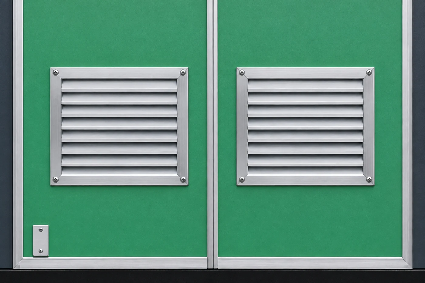
On the approved drawing, identify where air enters, which compartment it passes through and where heated air leaves. Check whether partitions, cable routes or installed accessories change that route. An opening with a large outside dimension may include blades, mesh or protective construction that restricts flow. Request the relevant effective-area or thermal information from the designer rather than estimating it from a photograph.
Inspect the route around the enclosure as well. A free opening can still draw warmer exhaust air back into an inlet or face a nearby obstruction. Ask the supplier to identify required installation clearances and explain how those dimensions relate to the proposed foundation. Preserve access routes for operation and maintenance alongside any cooling space.
Review temperature performance within the complete enclosure design. The manufacturer should explain how the proposed air path works with the other protective features of the supplied construction. A larger opening is not automatically an acceptable improvement if it changes that construction. Keep the approved arrangement as the reference for any proposed modification.
The publicly available IEC preview states that its covered designs use natural ventilation and identifies matters requiring agreement for other ventilation arrangements. Consequently, adding a fan is a design change to review, not a generic cure for an uncertain temperature problem. Ask what evidence covers the proposed cooling arrangement and what must be agreed for that specific configuration. IEC 62271-202 scope
If forced ventilation is proposed, prepare questions about the power supply, control sequence, alarm response, maintenance access and operation after failure. The answers should come from the supplier's documented design. Avoid assuming that a fan's nominal free-air flow equals delivered flow through the installed enclosure. Grilles and the complete route affect the operating condition.
Discuss the operating response when required cooling becomes unavailable. Depending on the approved design, the response may involve an alarm, load restriction or other controlled action. Have the responsible engineer approve it. An instruction to keep running until an operator notices overheating is not a substitute for an agreed operating plan.
The following table is a proposed review worksheet, not a standard's numerical acceptance table. Populate it with the project's approved documents and the supplier's evidence. Its purpose is to connect each question to a record that can actually be checked.
| Review item | Evidence to request | Installation check |
|---|---|---|
| Heat sources | Transformer loss declaration and equipment schedule | Delivered equipment matches the assessed combination |
| Air route | Approved compartment and ventilation drawings | No unapproved obstruction or altered partition |
| Surroundings | Supplier-required clearances and civil layout | Walls, fences and storage preserve the agreed space |
| Cooling arrangement | Configuration-specific thermal evidence | Natural or forced cooling matches the approved design |
| Operation | Accepted load and ambient assumptions | Observation records identify the actual conditions |
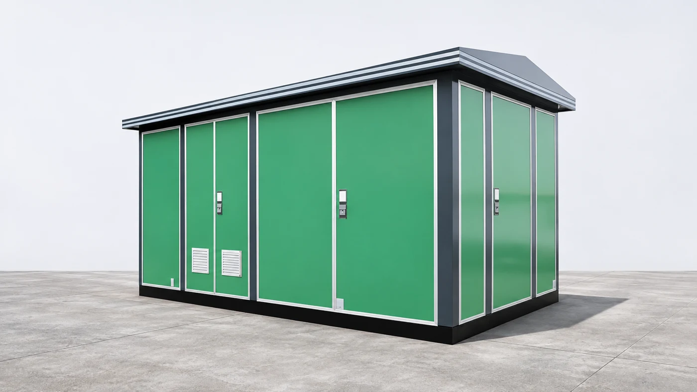
Before energization, compare delivered equipment with the approved arrangement and record differences. Check for packaging left near openings, unapproved screens, storage beside louvers or civil work obstructing access. Photograph the relevant areas from outside the safe work boundary. Have qualified personnel inspect internal conditions under the project's isolation and access procedures.
HSE provides guidance on the selection, use and maintenance of high-voltage switchgear. Coordinate work on the substation with the applicable equipment safety procedures. HSE switchgear guidance Do not cut extra vents, remove guards or leave doors open as a permanent cooling measure. Such changes need design review because the enclosure has several protective functions. If an apparent restriction is found, document it and ask the manufacturer for a corrective instruction tied to the unit. This creates a reviewable remedy instead of an undocumented field alteration.
During commissioning, follow an approved observation plan that identifies load, ambient conditions, measurement points and responsible personnel. Comparing temperatures taken under unrelated conditions can mislead the acceptance decision. Keep the original readings, instrument details and observation times so a later service visit can distinguish a changed operating condition from an equipment defect.
First establish whether the reported temperature is outside the documented operating criteria and whether the measurement location is meaningful. Then compare the current load and site conditions with the design assumptions. Inspect for obstructions and recent changes before deciding the enclosure needs different cooling equipment. This sequence prevents an expensive modification from masking a simpler installation problem.
Next review changes to the equipment schedule. A transformer replacement, new internal equipment or altered compartment layout deserves attention even if the exterior looks unchanged. Ask the manufacturer to assess the change using its design information. Keep the enquiry specific: identify the unit, the modification, the operating record and the evidence needed to close the issue.
For the surrounding distribution system, the ring main unit versus switchgear guide explains equipment boundaries, while the electrical panel replacement article covers a different project decision. Neither substitutes for the thermal review here. Use these related articles to organize the broader procurement conversation without treating all cabinet selection questions as one task. RMU and switchgear boundaries electrical panel replacement decisions
Send the supplier the installation drawing, transformer schedule, expected duty, environmental conditions and any project standard requirements. Ask for an explicit list of included and excluded assumptions. Request confirmation that the proposed delivered configuration is covered by the cited thermal evidence, or a clear plan for the additional engineering and verification needed.
Separate questions needing a numerical answer from those needing a drawing or procedure. For example, a request for declared losses needs a document, while a question about removing an obstructing wall needs a coordinated layout decision. Assign an owner and due date to each unresolved item so that procurement does not proceed on an unrecorded verbal assurance.
Where low-voltage reactive compensation is also planned, review its measurement and harmonic requirements separately using the power factor correction panel sizing guide. Additional equipment should enter the appropriate equipment and heat schedules. A tidy document handover gives both the substation supplier and the site engineer a stable basis for approval. power factor correction panel sizing
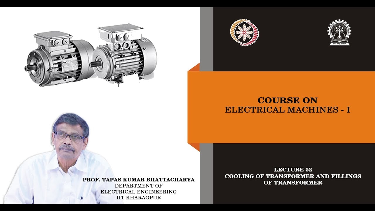
The NPTEL lecture below explains transformer cooling and related construction concepts. It provides educational background for discussing heat removal. It does not supply a ventilation design for this enclosure, replace the project specification or establish conformity of a photographed product.
Watch on YouTube — NPTEL IIT Kharagpur
No. Request the transformer's loss information, enclosure arrangement, operating conditions and the manufacturer's thermal assessment. Capacity alone does not define the heat that the particular enclosure must manage.
Only after the proposed modification has been reviewed and approved for the specific assembly. Ask how the changed arrangement affects thermal evidence, protective construction, controls and operation following a cooling failure.
No. Its appearance does not establish effective airflow or the complete air path. Use the approved drawings, supplier information and applicable verification records to assess the delivered configuration.
Keep the equipment schedule, approved layout, thermal assumptions, test references, inspection photographs, commissioning observations and subsequent changes together. These records make future troubleshooting and equipment substitutions easier to evaluate.