A ring main unit is a type of medium-voltage switchgear, so comparing ring main unit vs switchgear means comparing a ring-oriented assembly with another specified switchgear arrangement. The useful purchasing question is which arrangement matches the network, protective devices, cable interfaces and maintenance strategy. An RMU label alone does not establish fault-interruption capability, extensibility or internal-arc performance. Begin with the approved single-line diagram, then compare verified ratings and functions. This guide explains that review for industrial buyers; operating and switching procedures must come from the network owner and the equipment manufacturer.
A distribution node may need two connections continuing a cable ring and another connection supplying a transformer. That functional requirement is different from a main intake requiring several outgoing feeders, a bus-section function, metering and coordinated protection. Identify each circuit on the drawing before choosing an enclosure or counting cabinet doors. Two assemblies with the same number of doors can contain different switching functions and have very different operating limitations.
Also distinguish the physical cable ring from its normal operating state. The existence of two possible supply routes does not mean the ring is always operated closed. The network owner determines the normally open point, permissible parallel operation and restoration strategy. A purchasing specification should state the intended operating arrangement without attempting to replace the approved switching instructions.
Translate the diagram into a schedule of ways: cable connection, transformer feeder, protection, metering and spare provision. State whether each way must switch normal load, interrupt a fault or provide an isolation function. This avoids assuming that a load-break switch, disconnector and circuit breaker perform the same duty. The appropriate combination depends on the actual device ratings and coordinated protection scheme.
| Project question | Ring-oriented assembly review | Other MV lineup review |
|---|---|---|
| How are circuits arranged? | Check ring ways and transformer take-offs against the diagram. | Check incomers, outgoing feeders, bus sections and metering panels. |
| Which device clears each fault? | Identify fuse-switch or breaker protection on each protected way. | Identify breaker, relay, CT and trip-supply responsibilities. |
| What can remain in service? | Request documented access and isolation limitations. | Request the declared compartment and service-continuity arrangement. |
| Can the installation expand? | Confirm a documented extension interface and permitted combinations. | Confirm panel compatibility, bus ratings and available floor space. |
| What must be maintained? | List mechanisms, cable connections, protection and indicators. | List breaker mechanisms, shutters, relays and accessible compartments. |
This is a functional comparison, not a declaration that one equipment family has higher ratings than another. The IEC 62271-200 publication scope covers AC metal-enclosed assemblies above 1 kV through 52 kV. A reference to that standard is not evidence that a particular quotation includes every classification or has passed every relevant test.
Rated voltage is only the beginning. Record the system voltage, frequency, earthing arrangement, required insulation level, continuous current and available fault duty at the installation point. Short-time withstand current, its duration and switching-device breaking duties answer different questions. Ask the engineer responsible for the fault study to confirm the values supplied to bidders, including any planned upstream transformer or network changes.
Do not treat a transformer power rating as a complete switchgear specification. The feeder may need to accommodate inrush, protection selectivity, cable thermal limits and utility requirements. A fuse selection needs the transformer and system information; a relay-controlled breaker needs CT data, settings responsibility and a reliable trip arrangement. The supplier should identify exclusions instead of silently assigning them to someone else.
Ambient conditions also change the comparison. Indoor and outdoor installations, altitude, temperature, condensation, contamination and flooding exposure affect equipment suitability. Record actual site conditions and ask for the manufacturer’s applicable service limits. A photograph of a robust cabinet cannot confirm ingress protection, corrosion resistance or suitability for an unusual atmosphere.
Internal-arc performance must be evaluated as a declared classification with installation conditions, accessible sides and test limitations. A short phrase such as “arc resistant” is insufficient for procurement. Obtain the supporting documents and confirm that the proposed room, pressure-relief direction and clearances agree with the equipment instructions. Changes to the building or cable trench can matter even when the electrical ratings remain unchanged.
The practical question during maintenance is which circuit must be isolated and what access is allowed. Request drawings identifying the relevant compartments, interlocks, earthing facilities and operating positions. Do not infer a permission to work on energized equipment from compartmentation terminology. Safe access remains a matter for competent personnel following the owner’s approved arrangements.
The UK Health and Safety Executive’s Keeping electrical switchgear safe addresses selection, operation and maintenance responsibilities. It provides useful management context; local law and the project’s engineering rules determine the requirements at a specific site. Neither a cabinet label nor a purchase order replaces those responsibilities.
List cable voltage class, conductor material, cross-section, number of cables per phase, insulation system and termination type. Then confirm the termination manufacturer’s compatibility with the proposed equipment interface. Physical fit, bending radius and installation access should be checked together. A smaller enclosure is not necessarily a smaller installed footprint if it needs additional rear access or a different trench arrangement.
Specify cable entry direction, gland or sealing responsibilities and the earthing interface. Confirm who supplies connectors, surge arresters, test accessories and cable supports. These items can materially change installed cost and delivery readiness. Ask for a dimensioned arrangement showing the equipment together with the room boundaries, access routes and cable space, rather than comparing brochure widths alone.
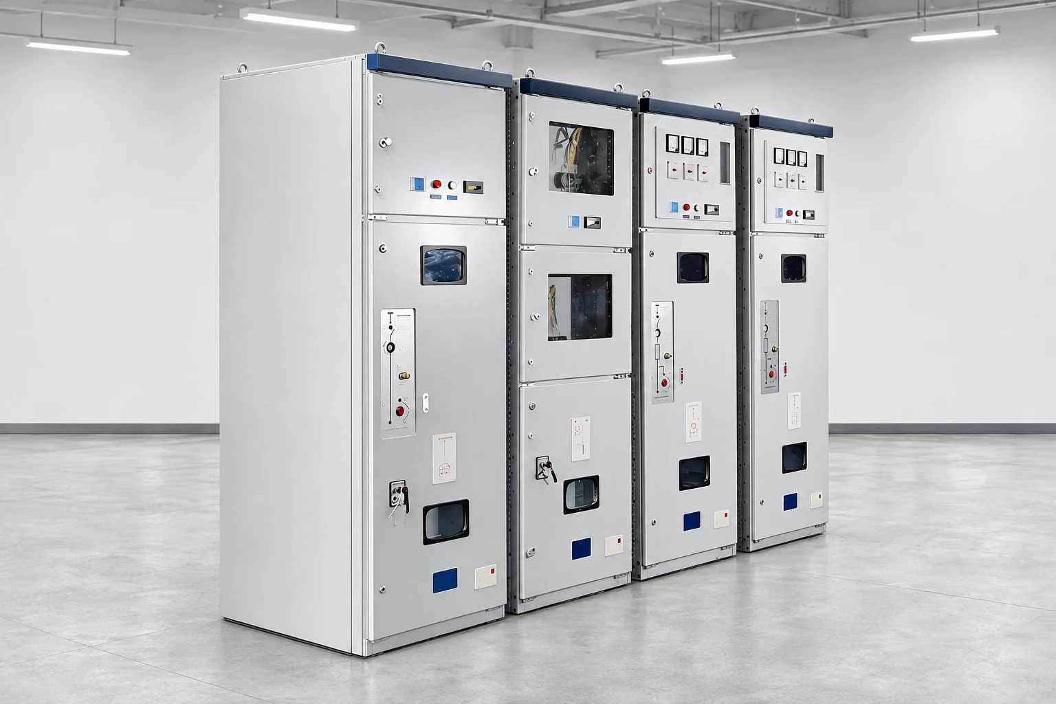
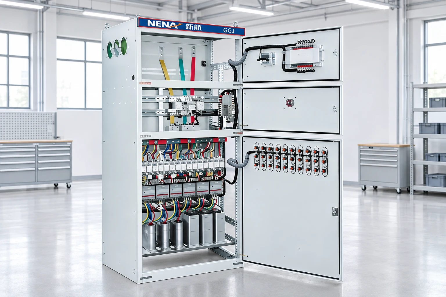
NENA’s HXGN15-12 ring-network switchgear page provides a relevant product family for an enquiry. The illustrated multi-bay cabinet identifies the equipment being discussed; the image does not verify its internal configuration, fault duty or certification. Request a project-specific drawing and data schedule before accepting a technical offer.
For a broader purchasing framework, use the industrial cabinet selection guide. Separate network-level distribution decisions from the downstream choice between a soft starter and VFD. Where drives form a major part of the load, coordinate the distribution specification with the drive temperature and altitude review; a satisfactory switchgear rating does not establish downstream drive suitability.
Issue the same diagram and schedule to every bidder. Require a response for each function and rating, including deviations, test-document references and the exact equipment designation. A technically incomplete offer should remain visibly incomplete in the comparison. Otherwise a cheaper price may simply omit protection, control power or accessories that another bidder included.
Compare the complete supply boundary: equipment, protection engineering, cable interfaces, control wiring, site assembly, commissioning support and documentation. State the required language and drawing format. Define the inspection and test plan before ordering, including which records are supplied and which activities are witnessed. Document acceptance criteria so that a general factory statement cannot substitute for the agreed evidence.
Finally, check delivery and maintenance access. Confirm the largest shipping section, lifting provisions, storage conditions, spare-parts arrangement and operator training. Expansion years later may require an obsolete interface or a planned outage. Obtaining that information during procurement gives the owner a realistic lifecycle comparison rather than a price comparison limited to the first delivery.
Consider two enquiry packages with the same nominal system voltage. The first contains a cable ring connection and one transformer take-off. The second contains several plant feeders, a bus section and metering. Calling both packages “12 kV switchgear” does not make their functions comparable. For the first, review the ring-way duties and transformer protection. For the second, review every feeder’s protection, the bus arrangement and the required maintenance access.
Now add a future second transformer to the first project. Ask whether it needs a reserved functional way, a documented extension or a separate assembly. Compare those options before ordering. An inexpensive non-extensible arrangement might remain suitable if a separate future installation is acceptable; an extension premium has value only when its interface and outage requirements suit the owner’s actual plan.
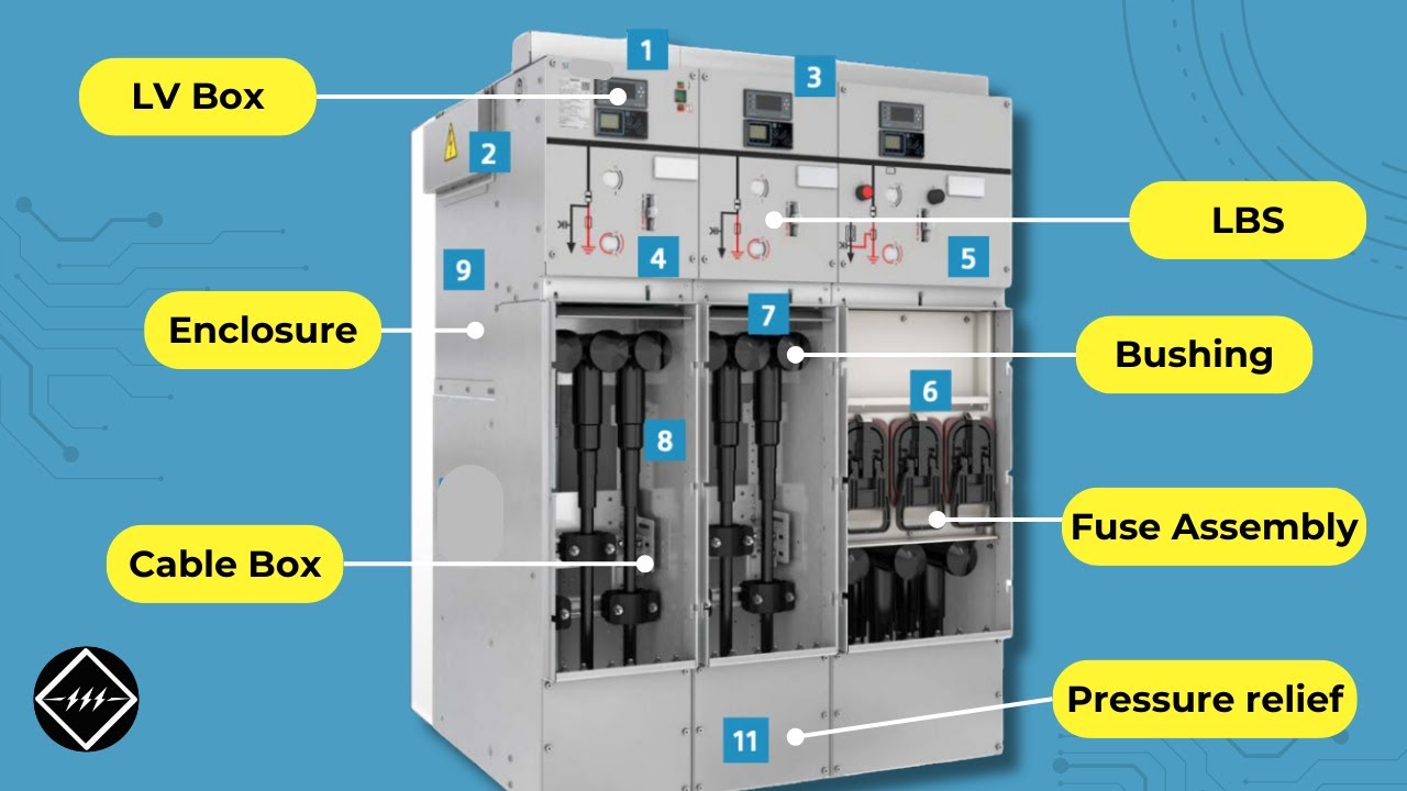
The educational video below explains RMU components and connects the single-line diagram to visible equipment functions. It is supplementary learning, not a switching instruction or approval of any NENA assembly.
Watch on YouTube — Gaurav J – TheElectricalGuy
An RMU belongs within the switchgear category. In purchasing discussions the comparison usually concerns a ring-oriented assembly and another medium-voltage lineup with a different arrangement of circuits and protection.
Do not assume that every way has fault-breaking capability. Identify the actual devices, their ratings and the protective scheme for each circuit in the approved diagram.
Only when the proposed design supports the required extension and the manufacturer documents the compatible interface and conditions. Reserve space alone does not establish electrical or mechanical compatibility.
Provide the single-line diagram, system and fault ratings, cable details, protection requirements, site conditions, access constraints, required test evidence and the intended future expansion.