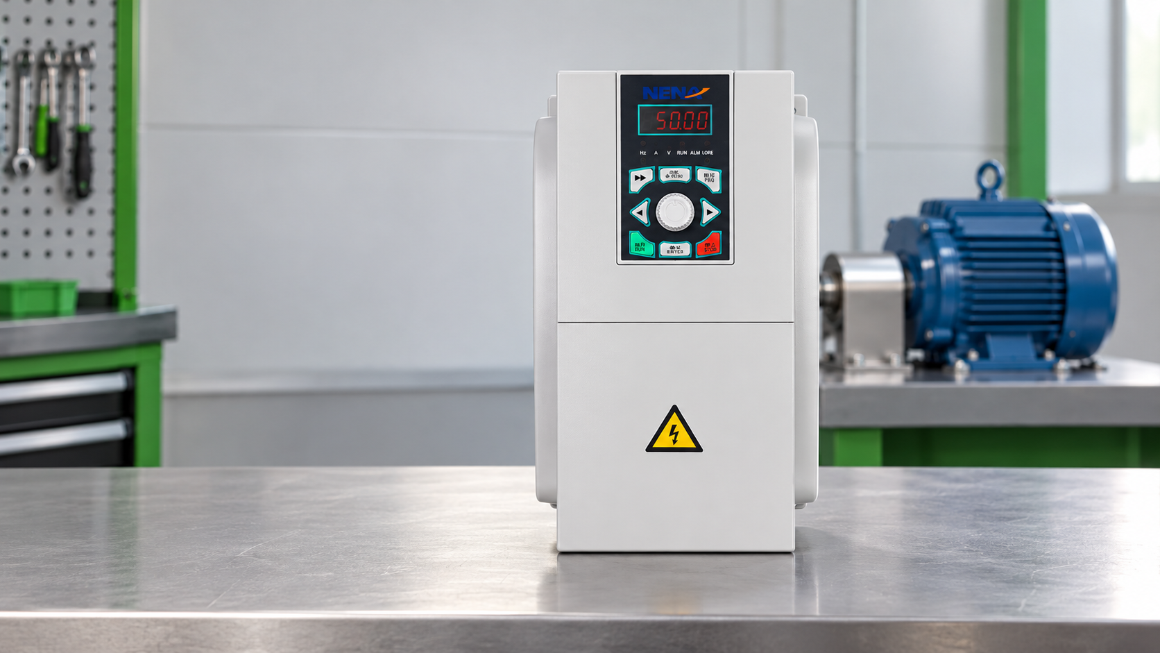
When Li Wei, a maintenance supervisor in Suzhou, started a packaging line after a weekend changeover, the conveyor motor tripped within seconds. He reset the breaker, checked the terminals, and watched the same failure repeat. A later review found that the controller had been selected for nominal motor power but not for the starting profile, ambient temperature, or the plant’s stop logic. The visible failure looked like a bad unit; the root cause was selection and specification.
Summary: A smart motor controller combines sensing, protection, control logic, a power stage, communications, and diagnostics around a motor application. The practical distinction is not a screen or a network port: it is whether the controller can make a measured decision and report why it made it. IEC 60204-1 provides a useful machine-safety reference, but it is not a product performance guarantee. Start with the motor data, duty cycle, fault response, and destination-market requirements before comparing brands.
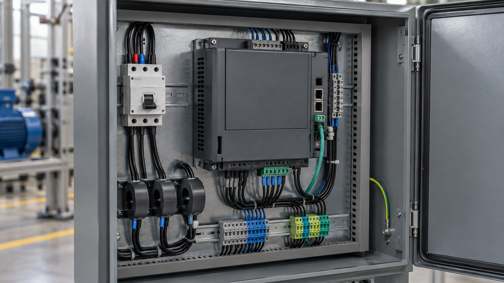
The first layer is sensing. Depending on the design, current transformers, shunts, voltage sensing, temperature inputs, speed feedback, or phase-loss detection provide the raw signals. The controller then compares those signals with configured limits and the motor’s expected operating envelope. A current reading is useful only when its location, sampling method, and response time are understood; an apparently precise value can still miss a short overload or a mechanical jam.
Procurement teams should request the input ranges, sensing accuracy, response-time definition, and test method. IEC 61800-5-1 is commonly referenced for adjustable-speed power drive safety, while IEC 60204-1 addresses electrical equipment of machines more broadly. Neither reference removes the need to verify the actual motor, wiring, enclosure, and installation conditions.
Protection is a coordinated function rather than a single trip threshold. Overload, short circuit, phase loss, locked rotor, under-voltage, over-voltage, over-temperature, and earth-fault conditions may require different actions: alarm, controlled stop, immediate isolation, or a restart inhibit. The control logic should preserve a clear event record so a technician can distinguish a process overload from a wiring fault.
This is where an intelligent motor controller differs from a basic contactor-plus-overload arrangement. A smart motor controller earns its name only when the measured condition, configured response, and recorded event can be traced together. The additional logic can reduce diagnostic time, but it also introduces configuration dependencies. Ask whether settings are retained after power loss, whether trip classes are documented, and whether a safety function is separate from a standard protective function. Where hazardous energy is involved, the lockout/tagout procedure remains an operational control; a software status bit is not a substitute for isolation.
The control algorithm translates an operator or PLC command into a switching sequence for the power stage. For an induction motor, that may mean contactor control, current-limited starting, torque-oriented control, or variable-frequency operation. Silicon carbide, IGBT, MOSFET, or electromechanical components can appear in different architectures; the relevant questions are switching stress, thermal path, fault containment, and serviceability.
Communications may use discrete I/O, Modbus, CAN, Ethernet-based protocols, or a vendor-specific interface. A digital motor controller is useful when its data is actionable: run status, load trend, trip cause, reset state, and maintenance counters should map to a documented register or signal list. A protocol label alone does not prove interoperability. Request a communication map, timeout behavior, and a defined state after network loss.
The total-cost case is usually in avoided downtime and faster diagnosis, not in the controller’s feature count. An illustrative calculation: if a documented fault record saves 20 minutes on each of 12 service events per year, the value depends on the plant’s actual labor and downtime rates. Label that calculation as site-specific; do not present it as a guaranteed return.
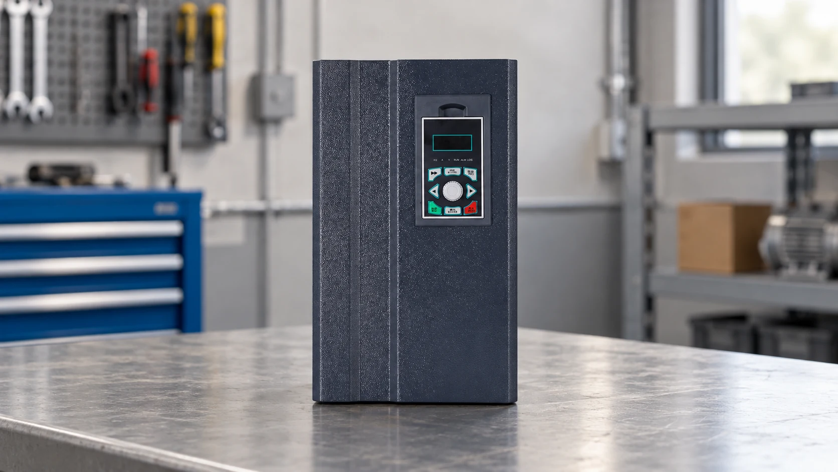
The names describe overlapping but different functions. A VFD changes frequency and voltage to regulate speed and torque; a soft starter primarily manages voltage during starting and stopping; a motor driver IC is an integrated circuit that drives a motor stage in equipment such as fans, pumps, actuators, or appliances. A smart motor controller may integrate one of these functions or sit above them as a supervisory and protective layer.
| Option | Primary job | Typical feedback and control | Where it fits | Procurement caution |
|---|---|---|---|---|
| Smart motor controller | Monitor, protect, command, and report motor operation | Current, voltage, temperature, status, and configurable logic | Connected industrial machines and panels | Confirm the exact power-stage function and safety boundary |
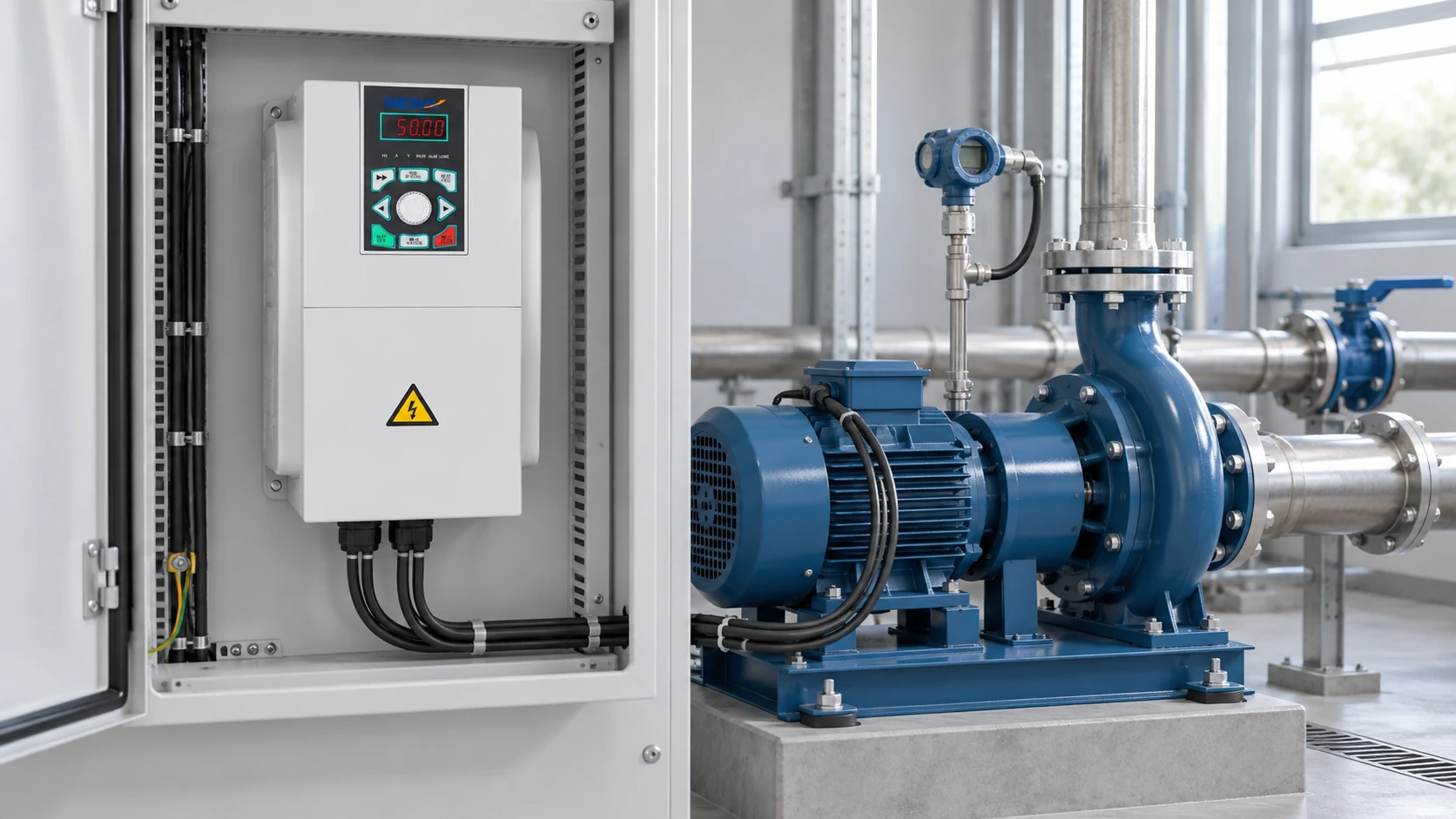
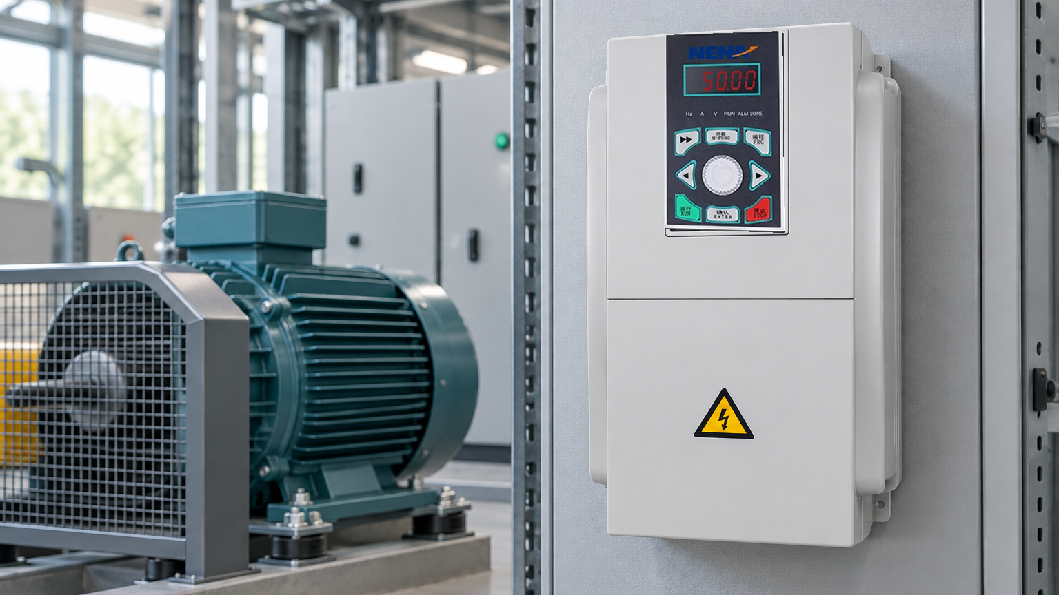
| VFD | Regulate motor speed and torque by varying frequency and voltage | Speed reference, current, frequency, fault state | Pumps, fans, conveyors, process lines | Check motor insulation, harmonics, braking, and EMC conditions |
| Soft starter | Limit inrush and shape acceleration or deceleration | Current, ramp, bypass, trip state | Fixed-speed motors with gentler starts | It does not provide full variable-speed control |
| Motor driver IC | Switch and regulate a low- or medium-power motor stage | Hall, encoder, current, or back-EMF inputs | Embedded products and compact equipment | Verify thermal design, firmware, and isolation requirements |
If a line needs speed control, review the frequency converter category rather than assuming that a controller’s monitoring functions include a VFD. If the requirement is limited to reduced starting stress on a fixed-speed motor, a soft starter may be the more proportionate architecture.
Use these procurement actions before approving a design:
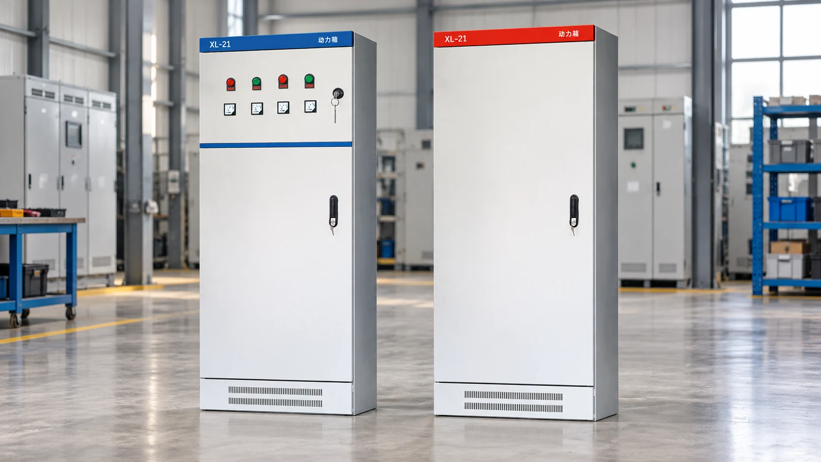
NENA / Zhejiang Xinhang Electrical can be considered when a project needs configurable motor-control equipment, panel integration, and documentation aligned to a stated application. The buyer should still evaluate the supplied model and evidence against the machine specification. A smart motor controller is one part of a complete cabinet and control architecture, not a shortcut around engineering review.
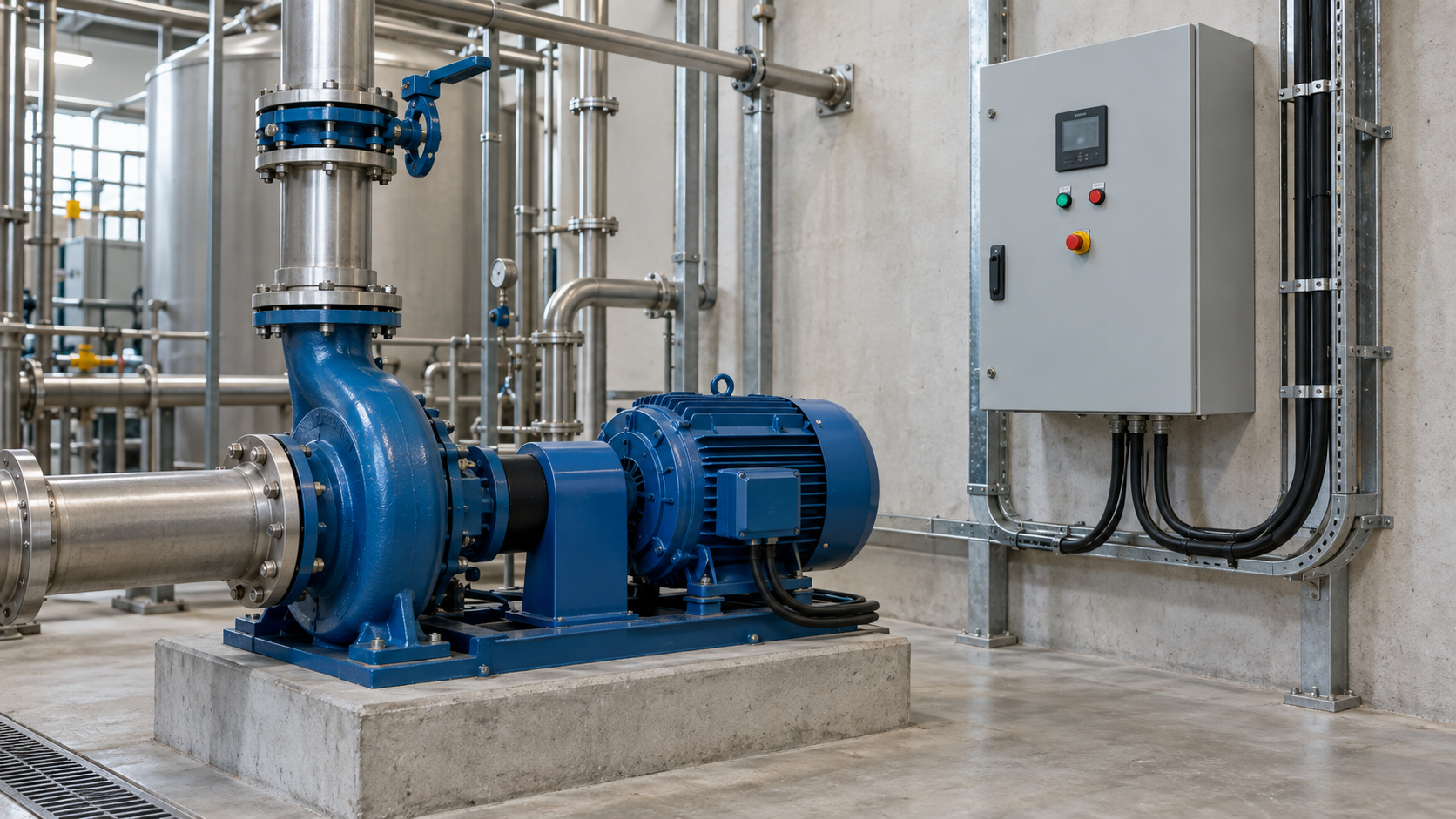
Intelligent motor management is the coordinated monitoring, protection, control, and reporting of one or more motors. It may combine local sensing with PLC or network data so that operators can see load state and fault cause. The exact functions depend on the controller architecture and configured limits.
A motor driver IC is an integrated circuit that switches and regulates power to a motor, often using inputs such as Hall sensors, an encoder, or back-EMF. It is usually a component inside embedded equipment rather than a complete industrial panel controller. Verify voltage, current, thermal, isolation, and firmware requirements before treating it as a system solution.
It samples electrical or mechanical signals, compares them with configured rules, and commands a power stage or contactor while recording status and faults. Some designs also exchange data with a PLC or supervisory system. The response to a fault may be an alarm, controlled stop, isolation, or restart inhibit, so the configured state machine matters.
Potential benefits include more consistent protection, faster troubleshooting, trend data, and easier integration with plant controls. The value depends on good sensing, documented parameters, and a maintenance process that uses the data. A network connection without clear diagnostics or ownership may add complexity without reducing downtime.
The useful rule is simple: specify the motor system’s behavior first, then choose the controller that can measure, protect, and explain that behavior. For an application review, documentation check, or cabinet requirement, contact NENA / Zhejiang Xinhang Electrical with the motor data and operating profile.