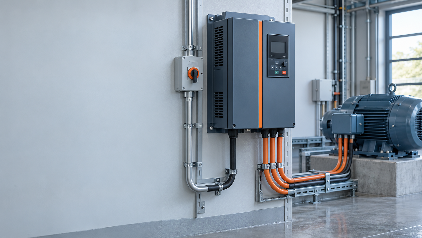
When a maintenance engineer in Manchester encountered repeated trips after fitting a drive to a conveyor, she checked the motor connection before replacing equipment. The conveyor stopped within seconds; the motor had been connected for a different voltage. This is an illustrative scenario, not a documented customer case: the fault was application setup, not proof of a defective drive.
Summary: A vfd for 3 phase motor must match supply voltage, motor nameplate current and load duty. Input and output are different circuits; never connect mains power to drive output terminals. A 230/400 V delta/star nameplate requires the connection appropriate to the actual drive output voltage. Have qualified personnel isolate, configure and commission the installation against the motor and drive manuals.
A variable-frequency drive controls motor speed by changing output frequency and voltage. Danfoss describes this operating principle; the US Department of Energy explains how adjustable-speed control can reduce losses in suitable motor systems.
Begin with the supply and motor records, not the motor’s kilowatt label alone. Record incoming voltage, phase count and frequency, then the motor’s rated voltage, current, frequency, speed and permitted connection. A drive with three-phase output does not necessarily accept single-phase input; confirm the exact input configuration in its manual.
For an illustrative motor marked 230/400 V delta/star, a 400 V output normally requires star connection, while a 230 V output requires delta. This statement applies to that exact marking, not every dual-voltage motor. Follow the terminal diagram and manufacturer instructions; do not infer a connection from wire colors or another motor’s photograph.
Use rated output current and overload capability to select a 3 phase VFD. Pumps, fans, conveyors and high-inertia machinery impose different starting and running demands. Check ambient temperature, altitude, enclosure ventilation and switching-frequency restrictions against the manufacturer’s duty tables; there is no universal derating percentage.
The DOE motor sourcebook explains motor speed. A four-pole motor at 50 Hz has a synchronous speed of 1,500 rpm; loaded induction-motor speed is lower because of slip. A vfd for 3 phase motor listing starts product review, not compatibility confirmation.
Installation belongs to qualified electrical personnel under the site’s isolation procedure. Lock out and tag out every relevant energy source, prevent mechanical movement, wait the manufacturer’s specified DC-bus discharge time and verify absence of voltage with suitable equipment. A blank display does not establish safe isolation.
For a conventional three-phase motor connection, the power circuit has three phase conductors plus protective earth. Protective earth is a safety connection, not a substitute for any phase conductor. IEC 61800-5-1 addresses electrical, thermal and energy safety in power-drive systems; local installation rules determine the required protective measures.
The 3 phase motor VFD manual identifies supply terminals, motor-output terminals, earth connections and control terminals. Labels vary by manufacturer. Never connect the incoming mains to the motor-output terminals; confirm terminal identity against the exact manual before energization.
Select upstream protection, conductor sizes, grounding and any residual-current protection according to the approved design. Check shield termination, cable routing and maximum motor-cable length. Long cables or a motor with unsuitable insulation may require a specified output reactor, dV/dt filter or sine-wave filter. Never perform an insulation-resistance test through the drive; disconnect equipment as instructed before testing the motor or cable.
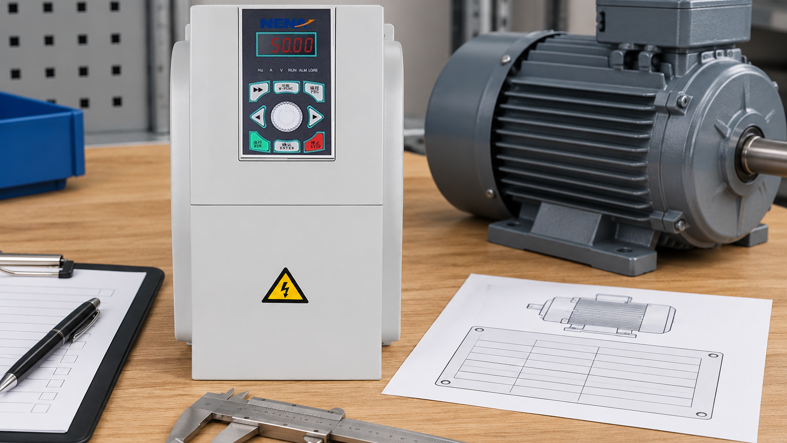
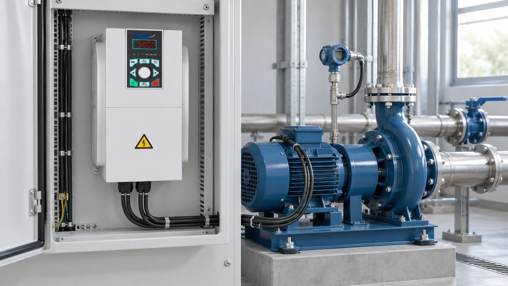
Reference-based parameter-review scene; use the physical motor nameplate and exact manuals, not illustrative labels, for settings.
Restore guards and confirm emergency-stop and safety functions through the machinery’s approved procedure before production release. With personnel clear, perform the permitted low-speed direction check, then controlled ramp tests. If direction is wrong, correct it only after isolation and discharge verification, following the approved wiring or parameter method.
Monitor motor current, vibration, temperature and process response over the intended operating range. A vfd for 3 phase motor should not be accepted solely because it turns the shaft. Assess low-speed cooling, acceleration under load and braking behavior; document alarms and the settings used to resolve them.
The DOE sourcebook discusses affinity laws for suitable centrifugal systems. Illustratively, at 80% speed, ideal fan shaft-power demand is about 51.2% of full-speed demand because 0.8 cubed equals 0.512. That is not a guaranteed electricity saving: static head, system resistance, motor losses and drive losses change the result.
Evaluate ownership cost using measured duty hours and load profiles. Include installation, filters, cooling, braking hardware, spares and downtime. Variable process demand strengthens the economic case for speed control.
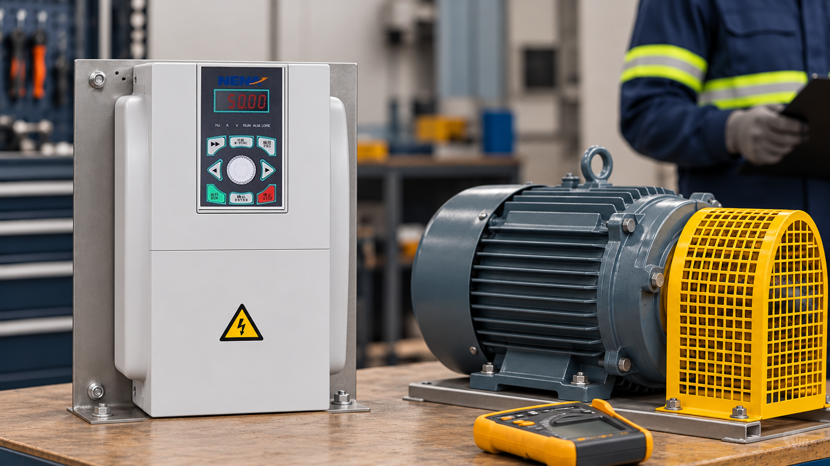
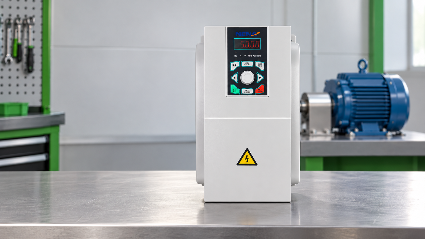
Conceptual commissioning scene with guarded equipment; no energized test, measured result or wiring procedure is demonstrated.
Choose the starting method around process requirements. An appropriately selected soft starter can suit fixed-speed duties needing controlled starting; continuous variable-speed control calls for a different evaluation.
| Method | Running-speed control | Application fit | Ownership considerations |
|---|---|---|---|
| Direct-on-line starter | No electronic speed adjustment | Fixed-speed load tolerating its starting behavior | Simple arrangement; assess supply capacity and mechanical starting stress |
| Soft starter | Normally fixed speed after starting | Fixed-speed systems needing a controlled start or stop | Starting-duty limits, bypass design and protection remain important |
| Variable-frequency drive | Adjustable within motor and load limits | Variable flow, coordinated conveyors or regulated speed | Adds setup, cooling, EMC and cable-design requirements; savings depend on duty |
Use the application dimensions below to prepare a specification before comparing the industrial motor-control products.
| Application dimension | Information to collect | Selection consequence |
|---|---|---|
| Variable-flow fan or pump | Flow range, system curve, static head and operating hours | Establish viable minimum speed and realistic energy-saving potential |
| Loaded conveyor | Starting torque, inertia and cycle frequency | Check overload duty and acceleration capability |
| Sustained low-speed operation | Torque demand and motor cooling arrangement | Confirm thermal limits or an approved independent cooling arrangement |
| Long motor cable | Cable length, cable type and motor insulation | Apply the manufacturer’s cable limits and filter requirements |
| Several motors | Individual currents, load behavior and protection | Assess summed current, separate overload protection and approved topology |
For NENA / Zhejiang Xinhang Electrical, submit a complete operating requirement when requesting a quotation. Evaluate the proposed equipment against the supplied documentation rather than assuming that a product family name establishes suitability.
Select a vfd for 3 phase motor against this documented duty; compare purchase price only after the proposed configurations are technically equivalent.
Usually, provided the motor, supply, drive and load are compatible. Check voltage, current, insulation suitability, cooling and the required speed range. Older motors or long cables may need additional evaluation and approved output filtering.
Start with motor nameplate current and the application’s overload duty, then check the drive’s rated output under actual installation conditions. Kilowatts alone are insufficient. Apply only the manufacturer’s documented derating and sizing guidance.
Manufacturer-approved multi-motor setups share output frequency — no independent speed control. Size for combined current/duty, add individual overload protection, confirm control mode. No output-side motor switching during operation unless explicitly approved.
Match supply input, motor output requirements and load characteristics first. Then check controls, environment, cable limits, safety integration and service documentation. Require written confirmation for unusual duties before ordering.
Reliable operation begins with a matched system and a documented commissioning process. For a NENA selection discussion, contact Zhejiang Xinhang Electrical with the motor nameplate, supply details and operating duty.