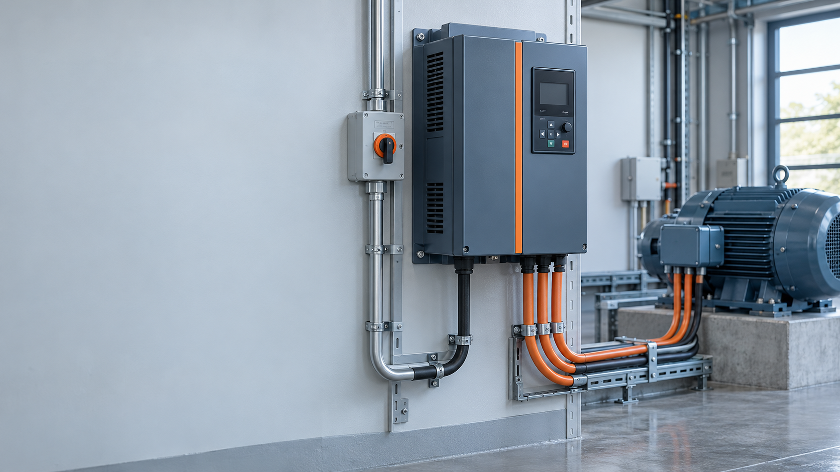
When a maintenance engineer in Shanghai encountered a fan that repeatedly tripped after a speed-control retrofit, she checked the motor nameplate, then watched the system trip again within minutes of ramping up. In this illustrative scenario, the drive itself was not necessarily defective: the motor current, required torque and acceleration time had not been checked against the application before selection.
Summary: A VFD drive varies the frequency and voltage supplied to a compatible AC motor so the machine can run at an appropriate speed instead of relying only on fixed-speed operation and mechanical throttling. For idealized centrifugal loads, power changes approximately with the cube of speed; that relationship is useful for screening opportunities, not a guaranteed saving [1]. Start with the load duty, motor nameplate and installation conditions, then verify the drive rating and protection requirements against the manufacturer’s documentation.
A variable-frequency drive is an electronic motor controller, often called an adjustable-speed drive or AC drive. It typically rectifies incoming AC to DC and uses power electronics to synthesize variable-frequency AC for the motor. The U.S. Department of Energy’s motor systems sourcebook treats adjustable-speed drives as one part of a system-level efficiency decision: whether speed control saves energy depends on the load, operating hours and baseline control method [1].
At a fixed grid frequency, an induction motor’s approximate synchronous speed is 120 times supply frequency divided by pole count, in revolutions per minute. A four-pole motor therefore has a 1,500 rpm synchronous speed at 50 Hz, while its shaft runs somewhat slower under load because of slip. A VFD drive changes electrical frequency to move that speed target; it is not a gearbox and does not make every motor suitable for every speed. The motor nameplate and NEMA’s Application Guide for AC Adjustable Speed Drive Systems are useful starting points for matching a drive, motor and driven load [2].
Below base speed, many drives adjust voltage with frequency to maintain magnetic flux. Above base frequency, available voltage may limit torque. A 60 Hz setpoint alone does not prove the shaft can meet the load; evaluate its torque curve and permissible motor range.
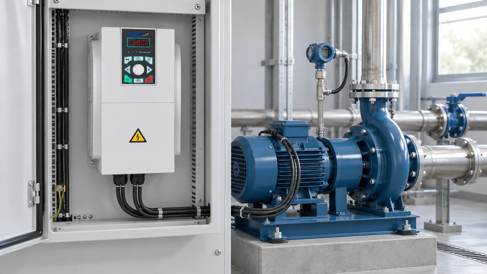
A typical drive has an input rectifier, a DC-link stage with energy-storage capacitors, and an output inverter. The rectifier converts AC to DC; the DC link smooths and stores energy; semiconductor switches in the inverter use pulse-width modulation to create a variable-frequency output. In this context a VFD inverter is the output conversion stage, although vendors also use “inverter” as shorthand for the complete drive. The system design must still account for input supply, grounding, cooling and the motor cable; the NEMA guide discusses application considerations for the complete AC adjustable-speed drive system [2].
The switching waveform differs from a utility sine wave. Long leads can increase reflected-voltage stress at motor terminals, and bearing currents can matter in some arrangements. Filters, cable practice or inverter-duty motor insulation may be necessary. Confirm limits in motor and drive documentation rather than adopting a universal cable-length threshold.
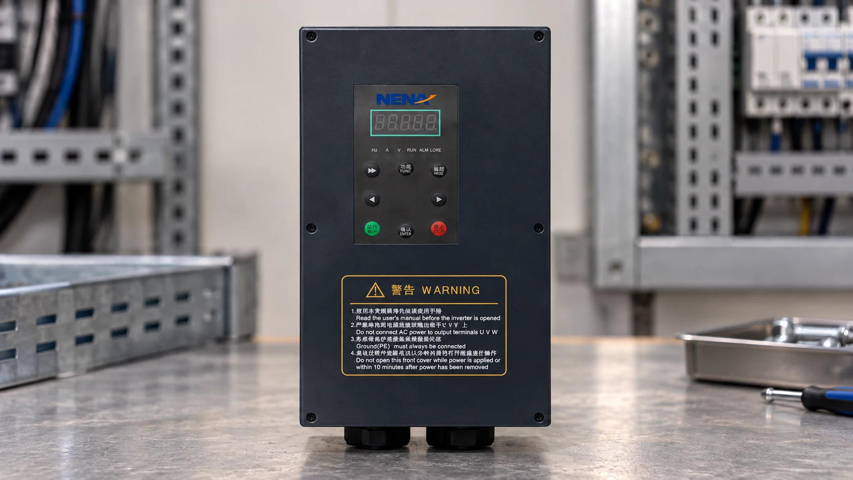
Fans and centrifugal pumps can be strong candidates when the process needs variable flow for many operating hours. Under the affinity-law approximation, reducing speed to 80% gives an idealized power ratio of 0.8 cubed, or 0.512. That is not a 48.8% site-energy promise: static head, system curve, motor and drive losses, minimum-flow constraints and actual duty time change the result. DOE recommends evaluating the complete motor-driven system, including operating profile, rather than treating a drive’s nameplate efficiency as the savings estimate [1].
Constant-torque duties such as conveyors may offer smaller energy savings, although speed control can improve the process. Compare the VFD drive‘s total ownership cost with the fixed-speed baseline: energy over the duty cycle, installation, commissioning, maintenance, downtime, enclosure and filtering needs. An illustrative annual energy cost is measured average input kW × operating hours × tariff; measure both options under comparable conditions before claiming payback.
This directional comparison follows DOE’s system approach [1] and NEMA’s application guide [2]; verify each option against the duty.
| Method | Speed and process control | Energy and cost tendency | Compatibility and maintenance question |
|---|---|---|---|
| Fixed-speed starter plus valve or damper | Motor stays near line-frequency speed; restriction regulates flow | Lower control-equipment cost; throttling can waste energy at partial flow | Check process needs, starting current and mechanical components |
| Soft starter | Manages starting and stopping, not continuous variable-speed operation | Useful where startup is the issue rather than sustained speed control | Confirm bypass arrangement and required running speed |
| Variable-frequency drive | Adjusts motor speed across an application-approved range | Higher installed complexity; potential savings depend on duty cycle and load | Check motor insulation, cooling, cables, harmonics and service capability |
A soft starter and a drive solve different problems; rated kilowatts alone cannot establish suitability. For speed-setting and feedback detail, see how a VFD controls motor speed.
At the same 5.5 kW motor rating, two machines can demand different acceleration torque, overload duration and braking. Resolve these questions before requesting a drive rating [2].
| Application or constraint | Load behavior | Selection evidence to request |
|---|---|---|
| Variable-flow fan or centrifugal pump | Torque often rises strongly with speed | Flow profile, minimum speed, system curve, input current and annual hours |
| Conveyor or mixer | Often needs meaningful low-speed torque | Loaded start current, acceleration time, overload duty and cooling arrangement |
| High-inertia machine | May regenerate energy during deceleration | Stopping time, braking duty and permissible DC-link behavior |
| Long motor cable or harsh environment | Can increase insulation or enclosure demands | Cable length and type, ambient temperature, dust/moisture exposure and derating |
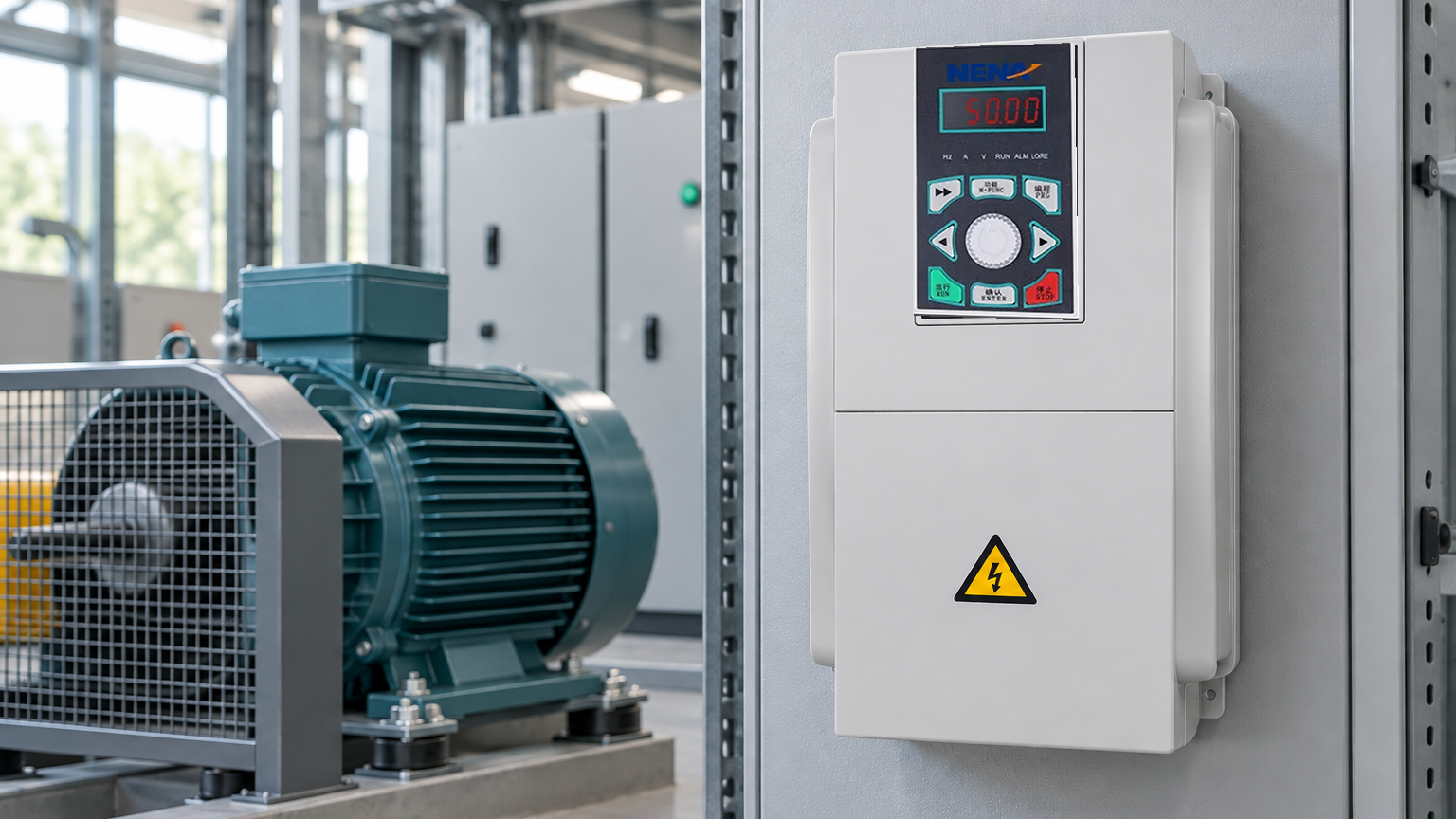
A VFD motor is generally a motor selected or designed to operate reliably from a variable-frequency supply; that label alone does not certify a particular speed range. Check continuous low-speed cooling, insulation stress, bearing provisions where relevant, and the motor manufacturer’s operating limits. For a concrete component example, review a VFD inverter listing, then obtain its actual ratings and manual before treating it as suitable for a specific load.
NEMA’s Application Guide for AC Adjustable Speed Drive Systems covers application considerations [2]; it is guidance, not product certification. The DOE sourcebook addresses motor-system efficiency [1], not an installation’s measured savings. For servicing in a covered U.S. workplace, OSHA’s 29 CFR 1910.147 addresses hazardous-energy isolation and verification [3]. A stop command from a VFD drive does not replace required isolation.
Ask suppliers for the exact model’s applicable safety, electromagnetic-compatibility and installation documents, and establish which requirements apply in the destination market. Grid conditions, enclosure location, machine integration and the claims made in sales material can change the compliance route. Unsupported certification or savings claims can delay acceptance, procurement and commissioning; a named standard on a webpage does not by itself establish independent testing or approval.
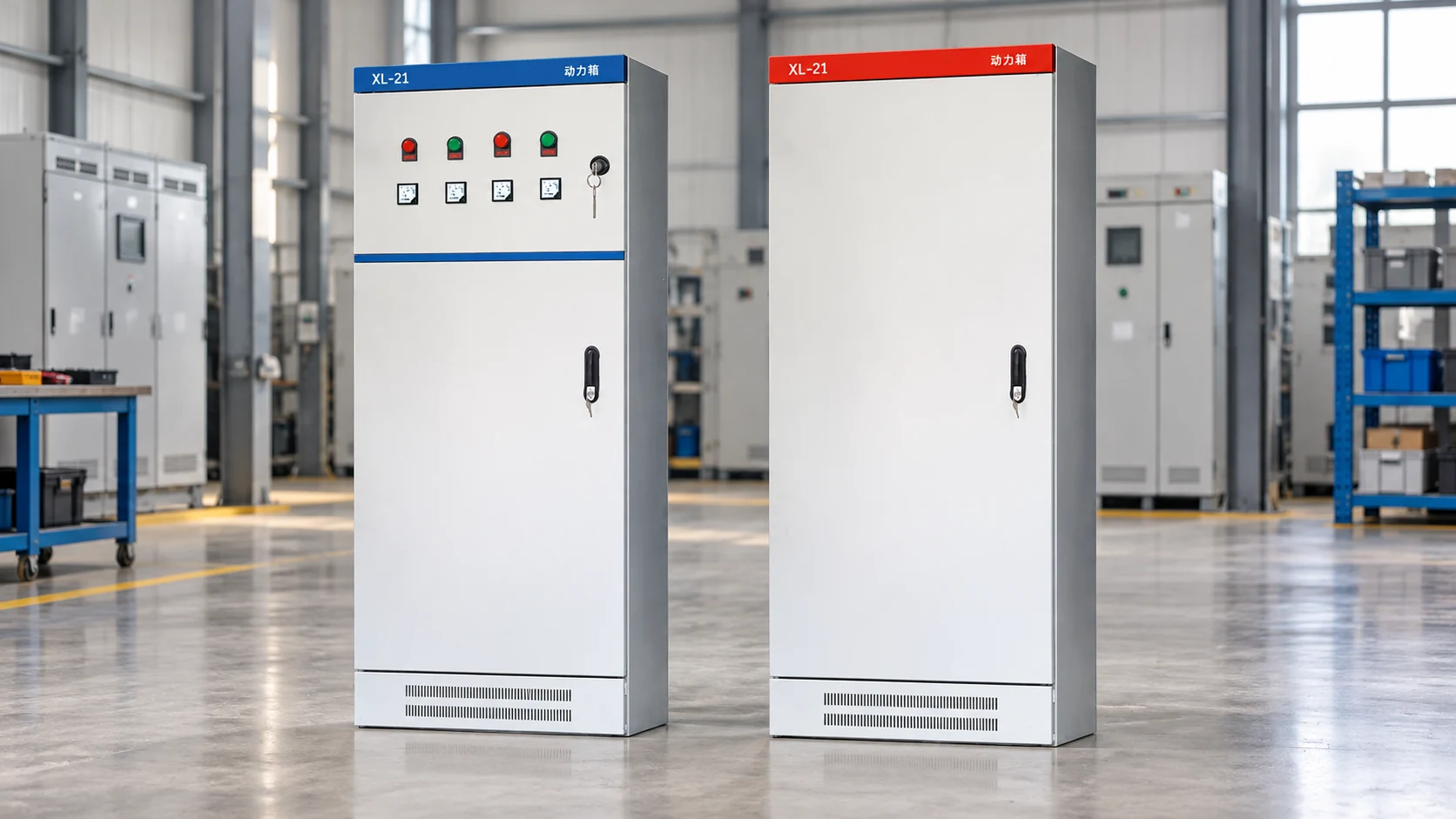
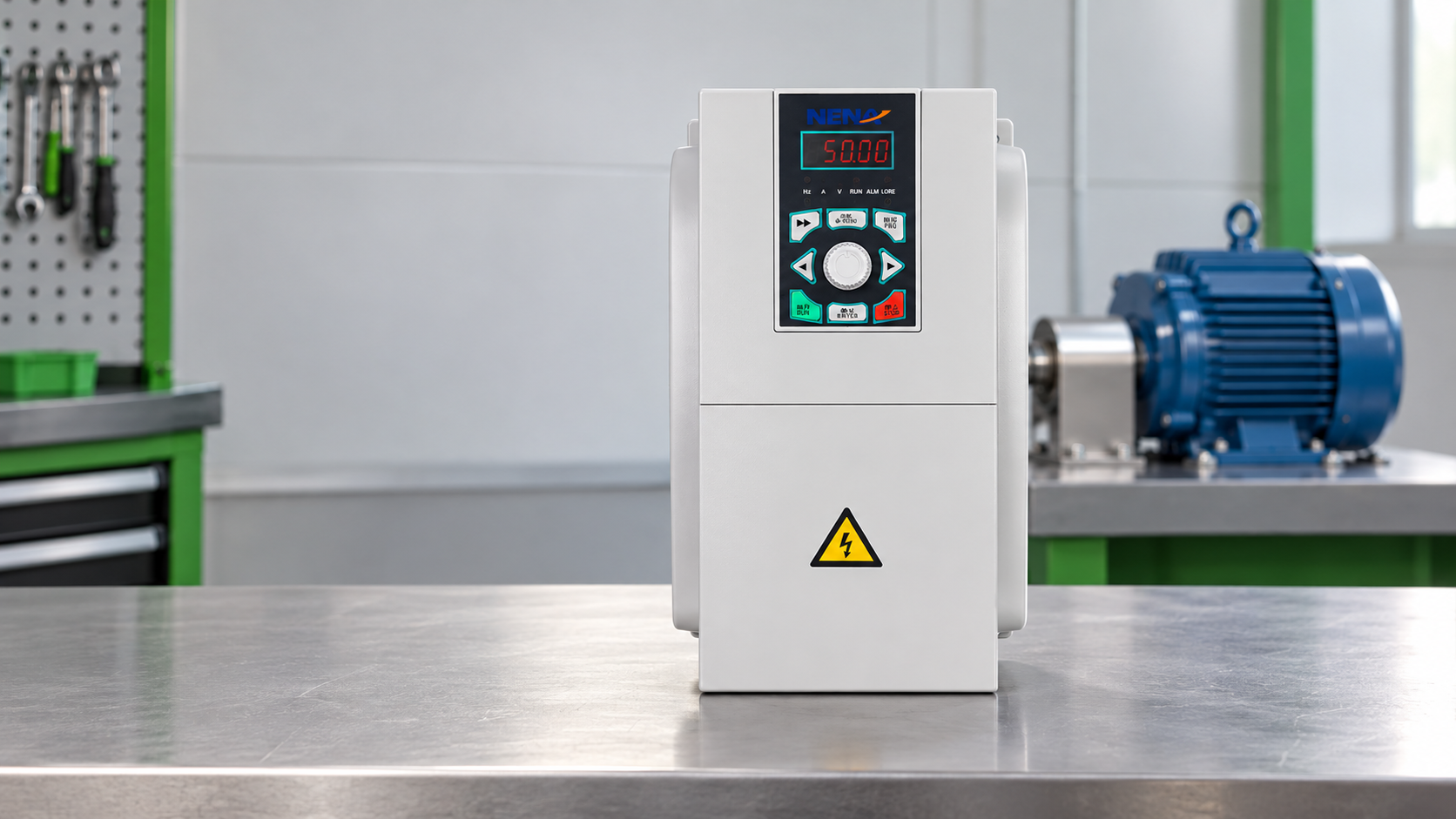
Zhejiang Xinhang Electrical’s NENA range includes the 820 variable-frequency drive as a drive component. Browse the drive and related product categories to identify a candidate, but separate drive selection from soft starters and control cabinets: those related items are not interchangeable motor-speed controllers. Ask for documentation matched to the model, motor and destination before ordering.
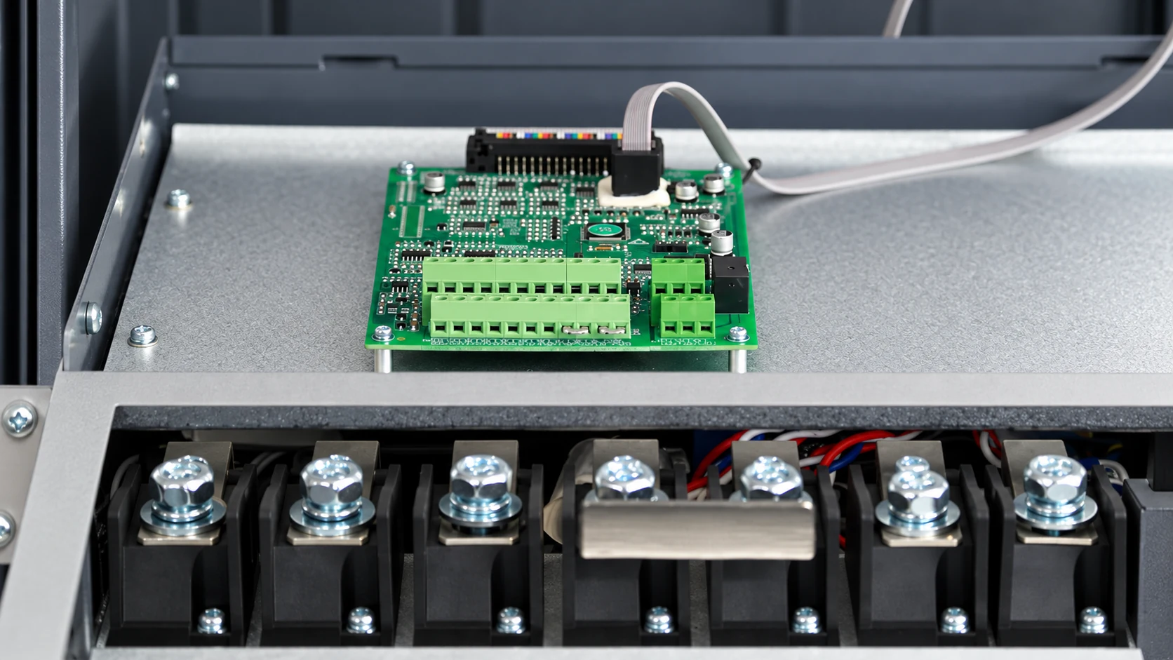
One common historical classification is voltage-source inverter, current-source inverter and cycloconverter. Most modern low-voltage industrial products encountered in routine procurement are voltage-source, PWM-based drives, but “three types” is not a universal purchasing standard. Ask which power topology and control mode a supplier actually offers, rather than assuming the category establishes application fit.
It is an AC motor intended or qualified by its manufacturer for operation from a variable-frequency drive over a stated range and duty. It can differ in insulation, cooling or bearing provisions, but there is no single feature set implied by the phrase. Verify its nameplate and manufacturer’s limits against switching conditions and sustained low-speed torque.
In industrial AC motor discussions, “inverter drive” often means a complete variable-frequency drive. Technically, the inverter is the DC-to-AC output stage within a typical drive, so the terms are not always identical. Confirm whether a quotation covers a complete controller or only a power-conversion component.
Three-phase AC induction motors are common, and some drives support permanent-magnet synchronous motors when explicitly designed and configured for them. Motor and drive support must be checked together; voltage, current, feedback, insulation and cooling requirements vary. Do not infer that any motor will work merely because it is rated at the same kilowatt value.
Specify the motor, load and operating profile first; a VFD drive follows from the duty, not a headline kilowatt figure. Contact Zhejiang Xinhang Electrical with the motor nameplate, load profile and installation conditions for a model-specific discussion.