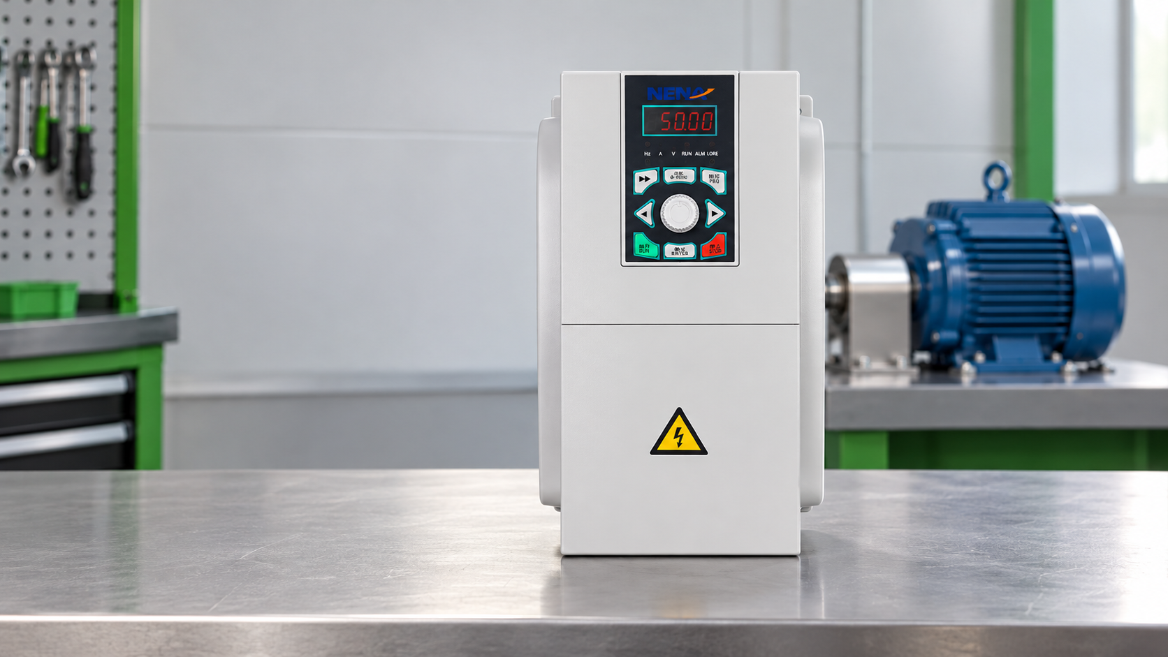
When Suzhou engineer Chen Rui faced a conveyor over-amp trip, he isolated power, checked the motor nameplate and swapped parts, but restart failed in three seconds. A controlled test revealed the real causes: improper inverter duty, acceleration profile and skipped autotune; the drive itself was not defective. This case shows troubleshooting should start with evidence, not replacement.
Summary: An AC Tech VFD trip is a symptom, not a diagnosis. Use lockout/tagout, preserve the fault log, verify the motor and cable, and compare parameters before changing hardware. IEC 61800-5-1 covers electrical safety; IEC 61800-3 covers EMC. We recommend a three-stage test: safe isolation, qualified powered measurements, and a controlled unloaded-to-loaded run.
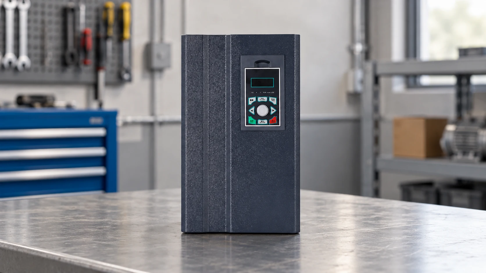
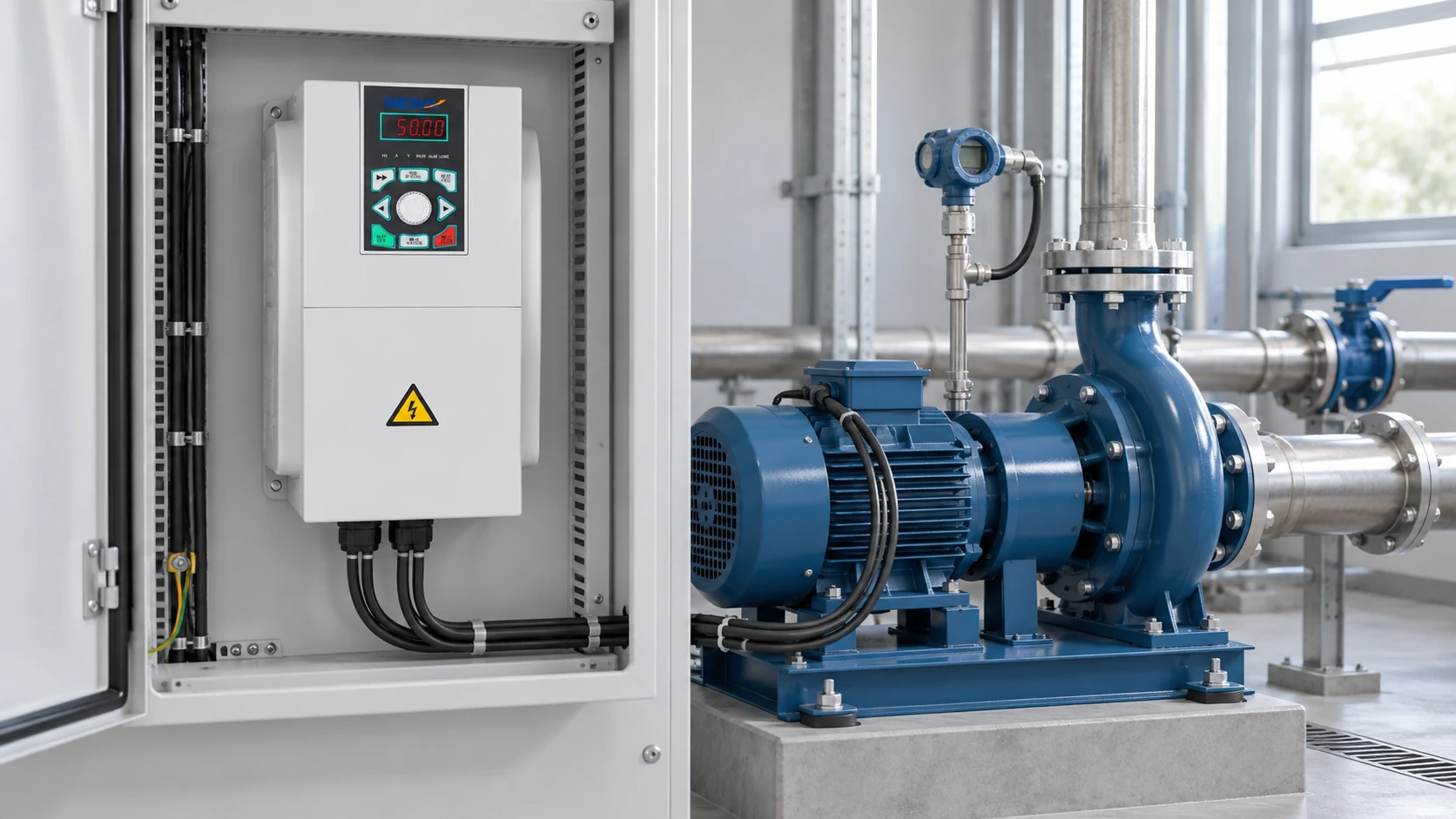
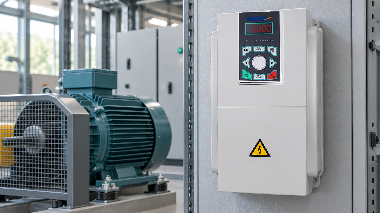
Variable-frequency drives regulate motor speed and torque by converting fixed-frequency AC into controlled output. A documented ac tech vfd troubleshooting record should connect the symptom to the load, wiring, and settings. A service record may pair an AC Tech label with Lenze AC Tech documentation or an OEM parameter set on the same panel. The practical question is not only whether an AC Tech drive replacement will run; it is whether it will deliver the required overload, braking, environmental protection, communication behavior, and maintainable records. For an equipment shortlist, use the AC Tech drive and frequency converter options as a category reference, then validate the duty and installation details.
Record the exact fault text or code, timestamp, commanded speed, output frequency, motor current, DC-bus indication, load state, and any preceding alarm. A phone photograph of the keypad and a copy of the parameter file preserve evidence that disappears after a reset. Note whether the event occurs at start, acceleration, steady speed, deceleration, or an external stop command; the timing narrows the fault family more effectively than a generic “drive failed” note.
Apply the site lockout/tagout process and verify absence of hazardous energy before opening the enclosure. IEC 60204-1 requires verification measures for electrical equipment of machines; the drive manufacturer’s discharge time and measurement points take precedence over a guessed waiting period. Do not use a standard multimeter on a live DC bus unless the meter, probes, and operator are rated for the measured category and voltage.
Run one controlled restart only after the initial evidence is captured. If the same trip occurs at the same frequency or load, treat it as a repeatable control, sizing, wiring, or mechanical issue. If it does not repeat, inspect incoming power quality, contactor sequencing, external interlocks, and recent maintenance activity. A power-quality analyzer can reveal phase loss, imbalance, or transient events that a keypad cannot; record the instrument class and sampling window with the result.
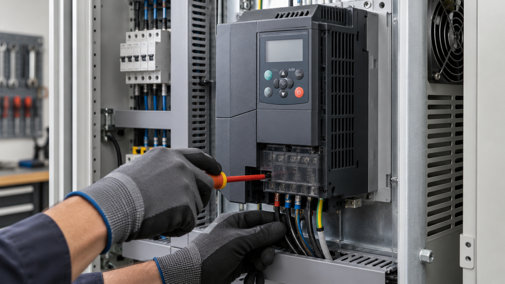
Check the power path and DC bus. With power removed and the bus proven discharged, inspect terminals for looseness, heat discoloration, contamination, and incorrect phase order. On a 400 V AC system, a healthy rectified bus is commonly near 540 V DC under nominal conditions (approximately 1.35 times line-to-line voltage); the value is a diagnostic reference, not a pass/fail limit. Measure only with a properly rated instrument and follow the site arc-flash boundary.
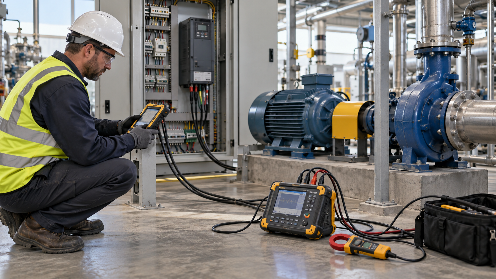
For a powered test, compare all three input phases and the output current on each phase under the same operating point. A true-RMS clamp meter helps identify imbalance, but a drive output waveform is not equivalent to a utility sine wave; use a differential probe and an oscilloscope designed for PWM output when waveform evidence is necessary. Never connect a conventional oscilloscope ground clip to a floating drive output.
Match duty before comparing replacement models. Classify the load as variable torque, constant torque, or high-overload duty; a fan, conveyor, hoist, and extruder do not share the same acceleration and braking profile. Capture the required speed range, starts per hour, overload percentage and duration, motor inertia, braking energy, and ambient temperature. A drive selected only by motor horsepower can be undersized for a high-inertia start or oversized in a way that complicates protection and cost.
The installation environment should be recorded at its worst credible condition: enclosure temperature, altitude, humidity, dust, corrosive vapors, vibration, and washdown exposure. Derating is product-specific; use the applicable Lenze or AC Tech data sheet rather than applying a universal percentage. Confirm whether the panel needs a line reactor, EMC filter, output reactor, dv/dt filter, braking resistor, or forced ventilation. These accessories affect heat, leakage current, cabinet space, and commissioning time.
| Decision dimension | Repair the installed AC Tech VFD | Like-for-like AC Tech drive replacement | Configured drive or complete cabinet |
|---|---|---|---|
| Performance | Preserves proven settings if the hardware is healthy | Retains the known motor and load match when data is available | Can add braking, filtering, cooling, and control changes together |
| Efficiency | No change unless a component or setting is corrected | Depends on the replacement topology and motor compatibility | Allows system-level loss and thermal design review |
| Compatibility | Highest with existing wiring and I/O | Requires terminal, firmware, and parameter verification | Requires a complete interface and network review |
| Durability | Depends on component condition and environment | Depends on new unit rating and enclosure conditions | Can improve protection when the enclosure and accessories are engineered together |
| Maintenance | Familiar hardware, but aging spares may be limited | New documentation and a controlled parameter backup are needed | Centralized drawings, labels, and test records simplify handover |
| Unit-cost tendency | Often lowest when the root cause is external | Moderate; commissioning labor can dominate | Higher initial scope, with potential reductions in repeat downtime |
| Total cost of ownership | Risk of another age-related failure if evidence is weak | Balanced when duty, EMC, and support are confirmed | Strongest when several panel changes are already required |
The honest comparison includes labor, production loss, commissioning, spares, and the cost of a repeat trip. For an illustrative calculation, two hours of downtime at a plant-assigned $300 per hour adds $600 before labor or parts; a $700 replacement that does not correct a sizing error produces a $1,300 avoidable event. Use the site’s own downtime rate and work-order history, and label assumptions in the approval record.
When the process does not require variable speed, compare soft starter coordination with a VFD on starting current, bypass behavior, protection, and maintenance scope.
Use these actions before requesting a quotation:
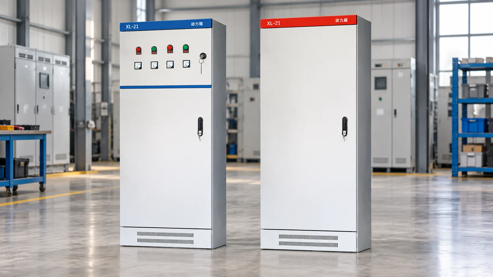
For multi-component panels, a complete cabinet integration scope can keep wiring, thermal design, and documentation under one review. Select against the duty sheet rather than horsepower alone, and retain the evidence used for approval.
Codes vary by series, firmware, and keypad language, so a generic list can mislead. Common families include over-current, over-voltage, under-voltage, overload, ground fault, over-temperature, and external-trip or communication faults. Read the exact code in the applicable manual, record the operating event, and confirm the motor, cable, and parameter evidence before replacing the drive.
Recurring problems include incorrect motor data, acceleration or deceleration that does not match the load, loose terminals, phase loss, insulation weakness, blocked cooling, excessive cable length, poor EMC layout, and a faulty external interlock. The first useful distinction is whether the fault follows the motor/cable or follows the drive when a known-good test setup is used. Correct the physical cause and document the final settings so the fault does not return after a reset.
Start with safe isolation and a visual inspection, then verify the motor and cable with the drive disconnected. A qualified person can measure input voltage, output current, and DC-bus behavior with correctly rated instruments; use a differential probe for PWM waveform work. Finish with an unloaded run, a controlled loaded run, and a comparison against the motor nameplate and application limits.
Over-amp trips usually indicate excessive acceleration torque, a jammed or high-inertia load, incorrect motor parameters, a short or grounded cable, or a drive that is undersized for the duty. Capture the current peak and frequency, check the mechanical system, verify motor data and autotune conditions, and test with the motor uncoupled where safe. If the trip persists on a documented known-good motor and cable, investigate the drive output stage or seek manufacturer service.
Reliable troubleshooting is measured by the quality of the evidence left for the next shift, not by how quickly a fault is reset. When the duty, compliance basis, and test record are clear, contact XINHANG engineering support to scope the right converter, starter, or cabinet for the installation.