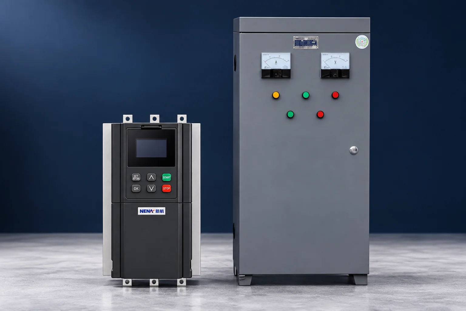
A soft starter is a strong candidate when a fixed-speed motor needs an adjustable electronic starting profile or a supported soft-stop function. An autotransformer starter is a different reduced-voltage option that uses transformer taps and a switching sequence to limit supply demand. Neither normally provides continuous speed adjustment. The choice should follow the motor’s accelerating-torque requirement, the supply-current limit, the starting cycle and the complete cabinet design. This soft starter vs autotransformer starter comparison explains the differences that matter when reviewing two quotations.
The discussion concerns three-phase induction motors. Product-specific ratings, tap arrangements, starting modes and protection must be confirmed in the exact supplied equipment documentation. Photographs of a cabinet cannot establish its internal circuit or starting capacity.
| Selection question | Electronic soft starter | Autotransformer starter | Evidence needed |
|---|---|---|---|
| How is starting voltage controlled? | Semiconductor control according to the selected starting mode | A reduced voltage obtained from a transformer tap, followed by transition to normal running | Power circuit and operating sequence |
| What can be adjusted? | Model-dependent voltage, current or other supported starting settings | Available tap choice and switching timing, according to the design | Actual settings and permitted combinations |
| How does supply current relate to motor current? | Do not apply an ideal transformer input-current calculation | Transformation reduces supply current relative to motor-side starting current | Clearly identified line-side and motor-side current data |
| What happens after acceleration? | Runs through the approved electronic or bypass arrangement | Starting transformer is removed from the normal running path | End-of-start and running-contactor sequence |
| Can it regulate running speed? | Not its normal function | No | Assess a VFD if variable running speed is required |
| Can it control stopping? | Only where the model provides a suitable stopping function | A conventional starter normally disconnects power and allows coasting | Required process stop and independent safety design |
| What limits repeated starts? | Starter and motor thermal duty, cooling and start duration | Transformer, switching equipment and motor starting duty | Permitted starts, consecutive starts and recovery conditions |
The table describes conventional arrangements, not guaranteed features of every product. For the electronic starting principle, see our motor soft starter overview. The Mar Athanasius College of Engineering induction-machine teaching notes provide the transformer-current relationship used below.
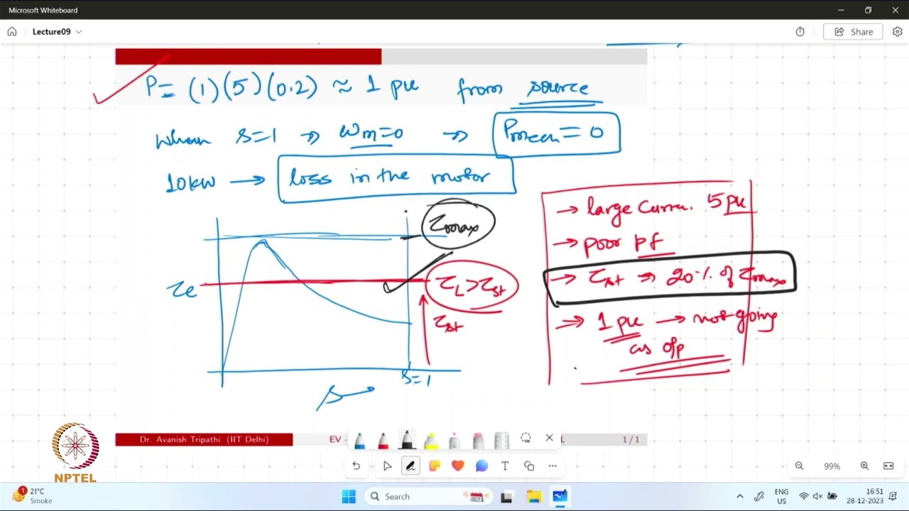
An autotransformer starter reduces motor voltage through transformation. Under ideal standstill assumptions, with tap ratio k equal to motor voltage divided by supply voltage, the motor starting current is approximately k times its direct-on-line value. The current drawn from the supply is approximately k² times that direct-on-line value. Starting torque is also approximately k² of the direct-on-line starting torque.
| Illustrative voltage ratio k | Motor voltage relative to supply | Motor starting current relative to DOL | Supply starting current relative to DOL | Starting torque relative to DOL |
|---|---|---|---|---|
| 0.50 | 50% | 50% | 25% | 25% |
| 0.65 | 65% | 65% | 42.25% | 42.25% |
| 0.80 | 80% | 80% | 64% | 64% |
These are calculations from ideal transformer and reduced-voltage starting relationships. They neglect transformer magnetizing current, losses and changes during acceleration. The ratios are examples, not a declaration of the taps supplied in a particular NENA cabinet. The comparison is with the same motor’s full-voltage starting condition, not with its rated running current.
For example, suppose direct-on-line starting would draw 300 A under the assumed conditions. At an illustrative k of 0.65, motor-side starting current is approximately 195 A while supply current is approximately 126.8 A. If direct-on-line starting torque were 200 N·m, the corresponding starting-torque estimate would be 84.5 N·m. These hypothetical values show why a quotation must identify where current is measured.
A semiconductor soft starter does not insert this transformer ratio between the supply and motor. Its waveform and active control mode must be assessed using the supplier’s starting data. Applying k² to both starting methods simply because their motor voltage appears similar can produce an incorrect comparison of supply demand.
A lower supply-current figure is useful only if the motor successfully accelerates the machine. Breakaway torque, resisting torque throughout the speed range and total inertia all matter. A reduced-voltage method cannot be judged from the first second alone; the motor may begin moving and then accelerate too slowly or fail at another point on its torque-speed curve.
Ask the machine supplier for the starting load state. A conveyor carrying material, an unloaded compressor and a centrifugal fan do not have identical torque requirements. Where the machine includes unloading, valves or other startup sequencing, document those conditions with the starter specification. A demonstration on an uncoupled motor does not establish performance in production.
Natural Resources Canada’s electric-motor reference guide explains why motor torque must meet acceleration and operating demands within the motor’s limits. Our three-phase soft starter selection guide applies that review to the broader equipment specification.
If a current limit is too restrictive, the available motor torque may not complete the start. A longer timer cannot create missing torque. Similarly, choosing a higher transformer tap can increase starting torque but also changes supply demand. Both proposals need a successful-start assessment against the same supply and load requirements.
An autotransformer circuit changes from its starting arrangement to normal running. The transition can be open or use a different engineered sequence. Specify which arrangement is offered and ask how the contactors and interlocks implement it. Do not assume that two cabinets with the same front-panel appearance contain the same transition circuit.
Evaluate motor speed, current and process behavior around that event. A satisfactory initial current reduction does not prove that the transition is acceptable. The timing and circuit need to be reviewed under the intended load, including permitted restarts. Request a record of the complete acceleration rather than a single starting-current reading.
In a soft starter with bypass, the bypass contactor provides the approved running-current path after starting. That is a different sequence from switching an autotransformer out of a starting circuit. Confirm what initiates bypass, what protections remain active and how a failure to complete the start is handled. The relevant details come from the actual circuit and manual.
Neither method has unlimited starting duty. Ask for allowable duration, current, starts per hour, consecutive starts and cooling interval under the specified ambient temperature and enclosure conditions. A transformer used only during starting still accumulates heat during repeated operations. An electronic starter also needs an adequate thermal margin for the entire start.
State whether the machine may restart while already hot or while still rotating. Describe the response required after a short supply interruption. Those conditions can alter the acceptable sequence and equipment selection. The manufacturer’s permitted operating cycle must govern; a generic claim that one method tolerates “frequent starting” does not define a usable duty rating.
Space and maintenance should be compared for completed assemblies. An electronic module may appear compact, but a finished installation can also require contactors, protection, ventilation, terminals and controls. An autotransformer cabinet needs room and thermal provision for its actual components. Compare external dimensions, access requirements and documented heat dissipation rather than inferring them from a product photograph.
For a discussion of why a long start changes thermal duty, read our soft starter ramp-time guide. Its distinction between a configured command and measured acceleration also prevents misleading comparisons between timer settings on different starting systems.
Provide motor voltage, rated current, frequency, connection and nameplate information; supply characteristics and any generator details; the driven machine, loaded or unloaded start condition; available inertia and torque information; maximum acceptable supply current; required acceleration and stopping behavior; and the complete start repetition requirement.
Ask each supplier to state the supplied scope explicitly: starter or transformer, contactors, disconnecting means, short-circuit protection, overload protection, control supply, enclosure, communications, field terminals and commissioning support. Also request the applicable assembly documentation and coordination evidence. A component approval is not by itself proof of the completed cabinet’s suitability for the site’s fault level.
Agree on acceptance criteria before purchase: successful loaded acceleration, acceptable supply response, acceptable transition behavior, correct protection and demonstrated repeat duty. If the actual application cannot meet both the supply-current ceiling and acceleration requirement, escalate the system design. Do not conceal the conflict by extending an unverified timer or weakening protection.
Electrical inspection and servicing require the site’s hazardous-energy procedure and appropriately qualified personnel. A stopped shaft or released start button does not establish isolation. CCOHS’s lockout and tagout guidance explains the distinction between operating controls and energy isolation. Local requirements and the exact equipment instructions apply.
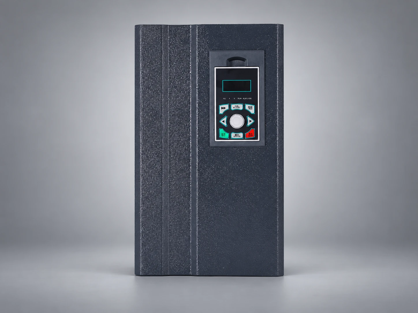
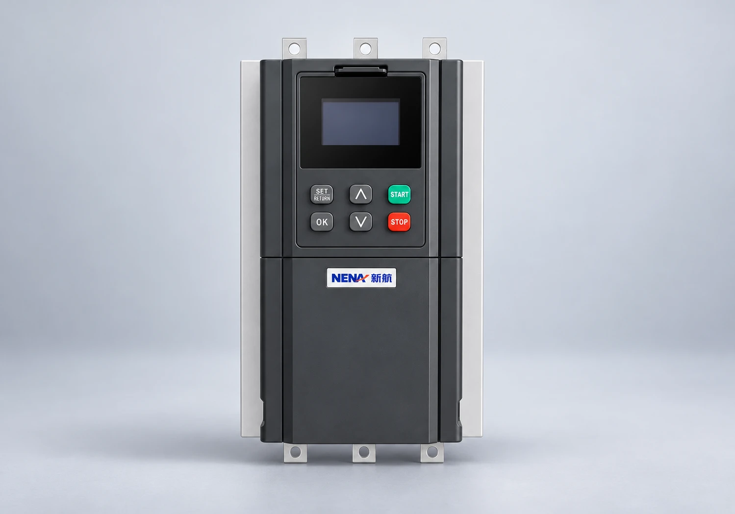
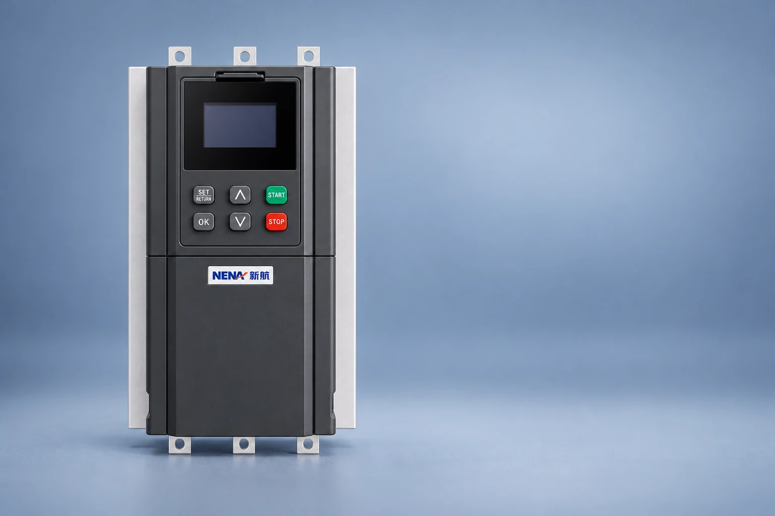
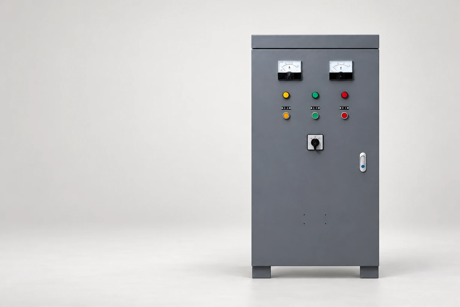
The NENA autotransformer reduced-voltage starter cabinet is a product reference for the transformer-based option. The NENA pump motor soft starter provides a relevant electronic starting reference. Ask for model-specific ratings, circuit details and duty confirmation for either proposal.
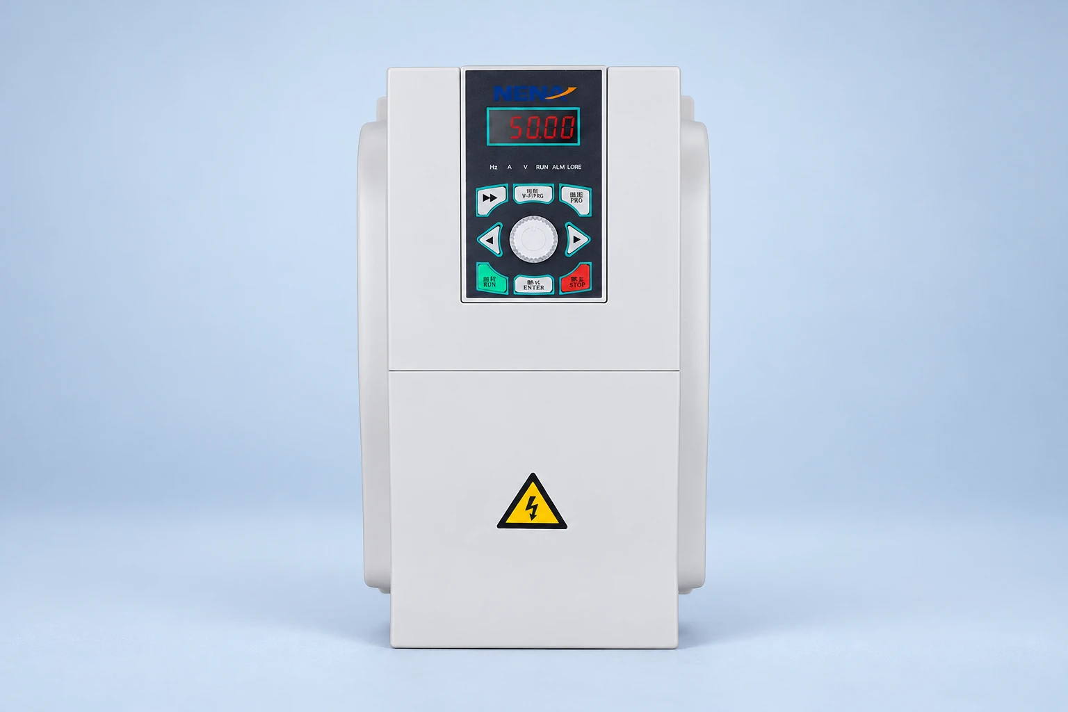
The illustrations retain the visible construction of the website products. They do not show the inside of either unit, demonstrate a specific transformer tap or establish comparative physical size. Selection should follow documented motor and application data, not the number or color of controls on the enclosure.
This NPTEL IIT Delhi lecture introduces induction-motor starting and speed control. It provides independent educational background; it is not a wiring instruction for either NENA product.
Watch on YouTube — NPTEL IIT Delhi
No. An autotransformer reduces starting voltage by transformation and changes to the running circuit. An electronic soft starter controls its starting waveform with semiconductors according to the supported mode.
Under the ideal standstill comparison, motor starting current is approximately 65% of its direct-on-line value, while supply current is approximately 42.25%. Actual equipment performance and transition behavior must be checked.
Neither normally does. If the process needs continuous speed adjustment, evaluate a suitable VFD and the motor-machine operating requirements.
No. Motor current, connection, starting torque, inertia, supply limitations, repetition and installation conditions all affect the required selection.