Soft starter ramp time is the configured period over which a starter changes its starting command, commonly the applied motor voltage. It is not necessarily the time the shaft takes to reach operating speed. The actual start depends on available motor torque, load torque, inertia, supply conditions and the active starting mode. Choose the setting from the exact starter manual and a documented loaded-start assessment. Making the ramp longer is not automatically gentler or safer: a motor that accelerates too slowly can accumulate excessive heat.
This guide concerns industrial three-phase induction motors using an electronic soft starter. It focuses on interpreting and checking the starting ramp, rather than providing universal parameter values or instructions for working on energized equipment.
| Time or setting | What it describes | What to verify |
|---|---|---|
| Start ramp time | The programmed evolution of the starting command in the selected mode | Whether the command is voltage, current, torque or a supported acceleration profile |
| Actual acceleration time | The measured interval for the shaft to reach the agreed running condition | Loaded speed, current and supply behavior throughout the start |
| Maximum starting time | A protection or supervision limit, where the model provides it | Its purpose, trip behavior and coordination with motor thermal limits |
| Current limit | The permitted starting-current command or ceiling | Whether it constrains or modifies the ramp, according to the manual |
| Stop ramp time | A separate stopping command | The resulting process stop; it is not a guaranteed braking time |
These are functional distinctions, not a list of features guaranteed on every model. IEEE’s introduction to soft starters distinguishes voltage ramping from current-controlled starting. Start with our motor soft starter overview if the basic operating principle is unfamiliar.
For an open-loop voltage ramp, the controller changes voltage without directly forcing the shaft to follow a specified speed trajectory. Some starters offer more advanced modes, but their parameter definitions differ. An identical number of seconds entered into two different products or modes does not establish identical starting behavior.
A lightly loaded motor may accelerate before the full configured ramp period expires. Depending on the controller, a detected running condition may change the sequence. Conversely, a loaded motor may need longer to accelerate, especially if current limiting constrains the available voltage or torque. Read how the particular controller determines end-of-start and bypass operation rather than assuming that its timer measures shaft speed.
If the motor is still accelerating at the configured ramp endpoint, full-voltage application can create a noticeable current or torque change. That observation does not prove that the electronic unit is defective. Review the complete start record and the active control mode. Also distinguish a successful acceleration from a motor that merely rotates: a slowly turning shaft can still represent an unacceptable prolonged start.
Document the start signal, first shaft movement, speed progression, current profile, supply-voltage behavior, running condition and any fault indication. Use instrumentation suited to the waveform and task. A single peak-current number cannot tell you whether the motor accelerated smoothly, stalled temporarily or experienced a supply disturbance.
Before optimizing time, check that the motor develops enough torque to begin moving the actual load. A reduced-voltage start also reduces available torque. A setting that works on an empty conveyor may fail when material is present. Pump valve conditions, compressor unloading and the mechanical state of the driven machine can likewise change the start.
Lowering the initial command too far can leave the motor energized without useful acceleration. Extending the ramp in that situation does not remove the breakaway requirement. Raising a current limit blindly is not the answer either: the motor, starter, feeder and protective arrangement must all support the proposed duty. The aim is an acceptable start inside the documented operating envelope.
Natural Resources Canada’s electric-motor reference guide explains the need for sufficient accelerating torque without exceeding motor limits. For broader purchasing checks, see our three-phase soft starter selection guide.
A simplified mechanical estimate is t = J × Δω / Tacc. Here t is acceleration time in seconds, J is the total inertia referred to the motor shaft in kg·m², Δω is the change in angular speed in rad/s, and Tacc is the assumed average net accelerating torque in N·m. Net torque is motor torque minus resisting load torque. Convert RPM to rad/s using Δω = 2π × Δn / 60.
For an illustrative J of 2 kg·m², acceleration from zero to 1,400 RPM, and average net torque of 20 N·m, the estimate is 2 × (2π × 1,400 / 60) / 20 ≈ 14.7 seconds. If average net torque falls to 10 N·m, the corresponding estimate becomes approximately 29.3 seconds. These are hypothetical calculations, not suggested starter settings or product capabilities.
The model assumes a representative average torque. Actual motor and load torque change with speed, and a reduced-voltage start changes the available curve. If net torque becomes zero or negative at a critical point, a simple average can conceal a failure to accelerate. Use the estimate to request better inertia and torque information; final assessment requires the actual curves and manufacturer limits.
A gearing change also changes the inertia referred to the motor shaft. Do not add a driven machine’s inertia directly to the motor rotor inertia without accounting for the transmission. When those inputs are unknown, tell the supplier what the machine does and provide measured starting records rather than presenting a guessed calculation as verified design data.
Motor heating during a start depends on both current and duration. As a deliberately simplified comparison, consider the index ∫(I/Irated)²dt. A constant 3-times-rated current for 8 seconds gives 72 normalized seconds; the same current for 24 seconds gives 216. The duration has tripled the index. Neither number is a permitted thermal limit, and a real start usually has changing current.
This comparison does not calculate winding temperature or replace the motor and starter thermal models. It highlights why a visually smooth but prolonged acceleration can be unacceptable. A current reduction can also be offset by a longer duration, so compare the full traces and documented duty rather than choosing the lowest peak alone.
Starts per hour, consecutive starts, cooling intervals and hot restarts matter alongside a single ramp. A successful cold demonstration does not establish that the machine can repeat the sequence throughout production. Check the starter’s starting-duty rating and the motor’s permitted starts, including enclosure temperature and site conditions. A catalogue adjustment range is not permission to combine its maximum current and maximum duration.
| Observed behavior | Investigate first | Useful evidence |
|---|---|---|
| Energized motor does not move promptly | Mechanical restriction, connection, initial command and breakaway requirement | Fault record, supply data and the actual loading condition |
| Motor moves but acceleration remains slow | Current limiting, load curve, inertia and voltage availability | Current and speed traces over the whole start |
| Noticeable surge near the ramp endpoint | Whether acceleration is complete when the command reaches its endpoint | Time-aligned speed, voltage and current records |
| First start succeeds, repeated starts trip | Thermal recovery, start repetition and motor or starter duty | Operating history, temperatures, cooling intervals and fault codes |
| Stop causes pressure disturbance | Hydraulic behavior, valves and the supported stop function | Pump-system operating conditions and stopping records |
This table organizes a review; it does not diagnose a fault from one symptom. Preserve the trip information before resetting. Follow the site’s procedure if the motor stalls, overheats or behaves unexpectedly. Repeatedly restarting a stalled motor to try different times can worsen the condition.
First establish the motor connection, supply details, load state and approved starter configuration. Confirm the selected mode and parameter definitions in the exact manual. Have the responsible engineer establish a starting envelope that meets motor, starter, supply and process requirements before beginning an adjustment trial.
Record the baseline configuration. Make one authorized change at a time within that envelope, and retain the measured result with the load and environmental conditions. Define success through complete acceleration, acceptable supply response, acceptable mechanical or hydraulic behavior, correct protection and the required repeat duty. Do not approve a setting only because an unloaded motor sounds quieter.
Finally, document the settings, test conditions, acceptance results and permitted restart sequence. Include what operators should record after a trip and who may change parameters. If the process genuinely needs a defined speed trajectory or variable running speed, compare a suitable VFD rather than treating the soft starter’s voltage ramp as a speed controller. Our starting-method comparison explains another fixed-speed alternative.
Electrical inspection and servicing require qualified personnel and the site’s isolation procedure. A stop command is not isolation, and stored energy or an automatic restart can remain hazardous. CCOHS’s lockout and tagout guidance explains the underlying risks; the applicable local rules and equipment instructions govern the actual work.
Send the motor nameplate, supply voltage and frequency, load description, starting condition, measured acceleration time, current record, starts per hour, consecutive-start requirement and fault history. Explain whether the issue is slow acceleration, an endpoint surge, repeated tripping or process disturbance. Those are different requirements even when each is described as a ramp-time problem.
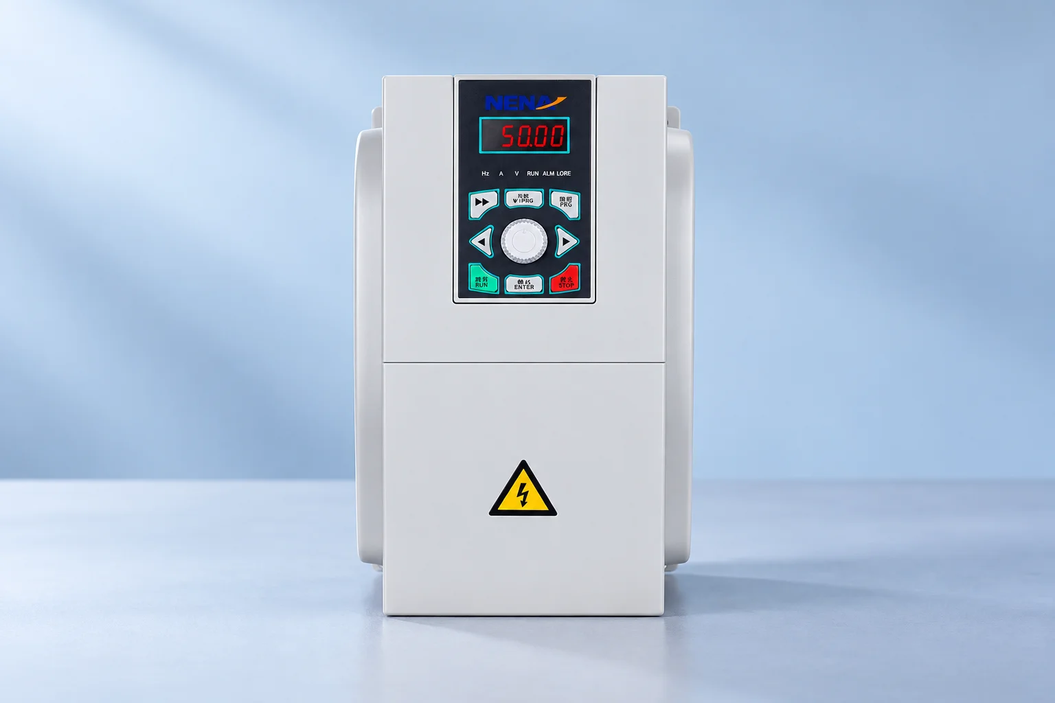
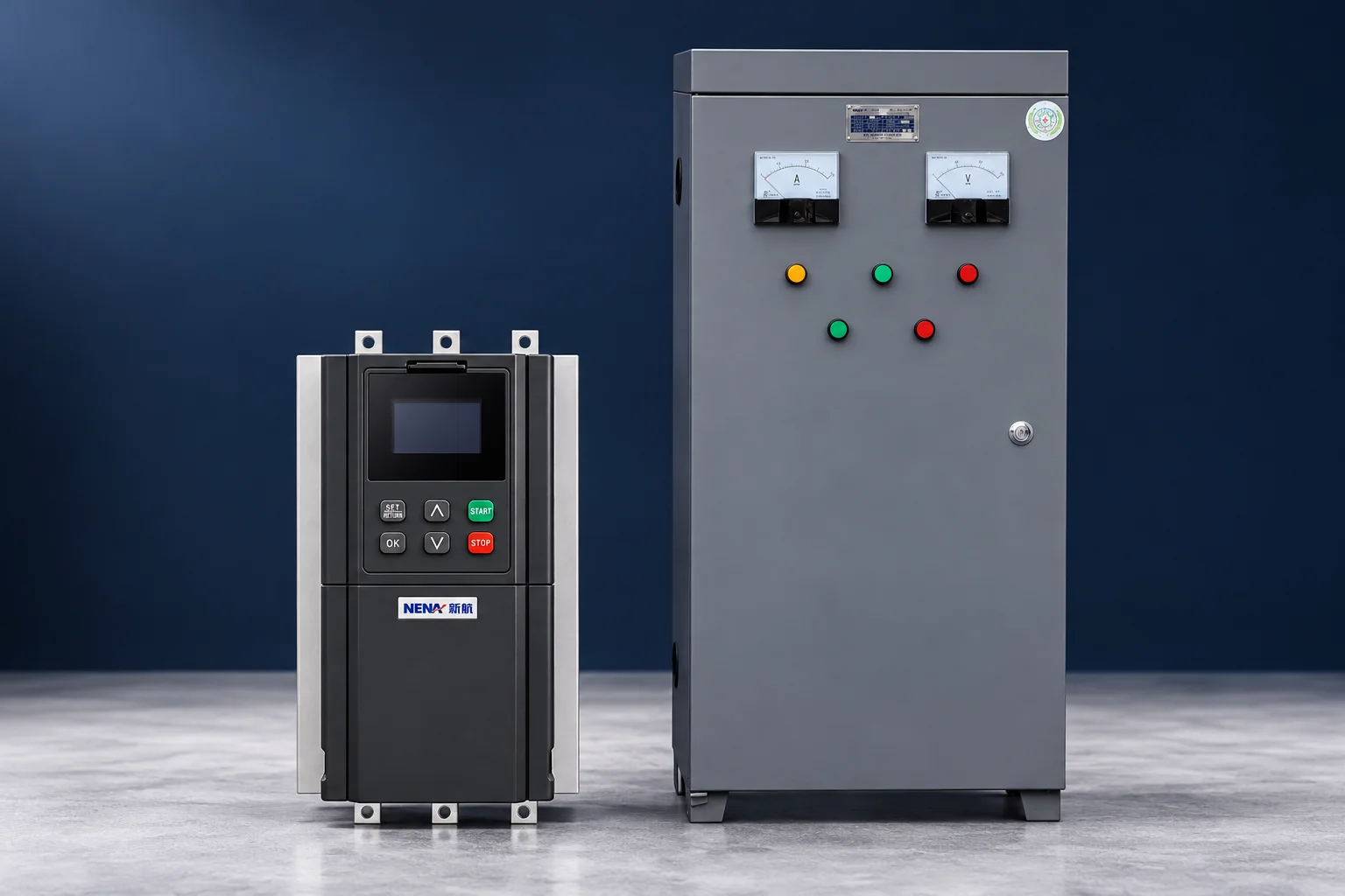
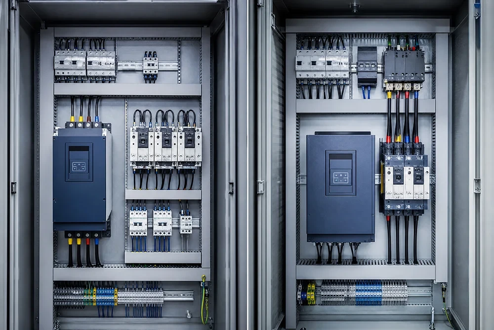
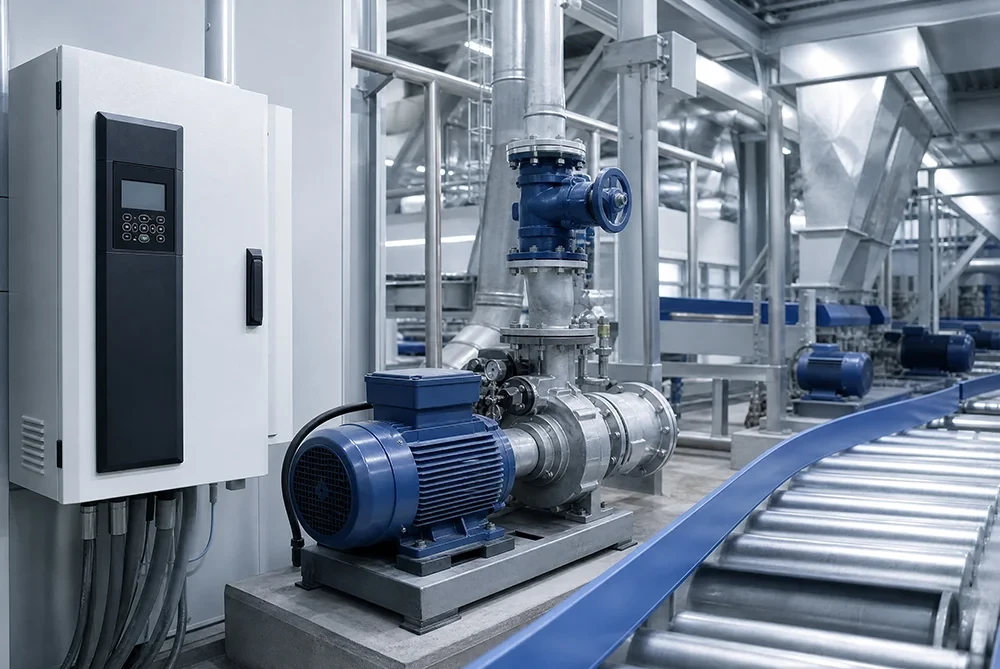
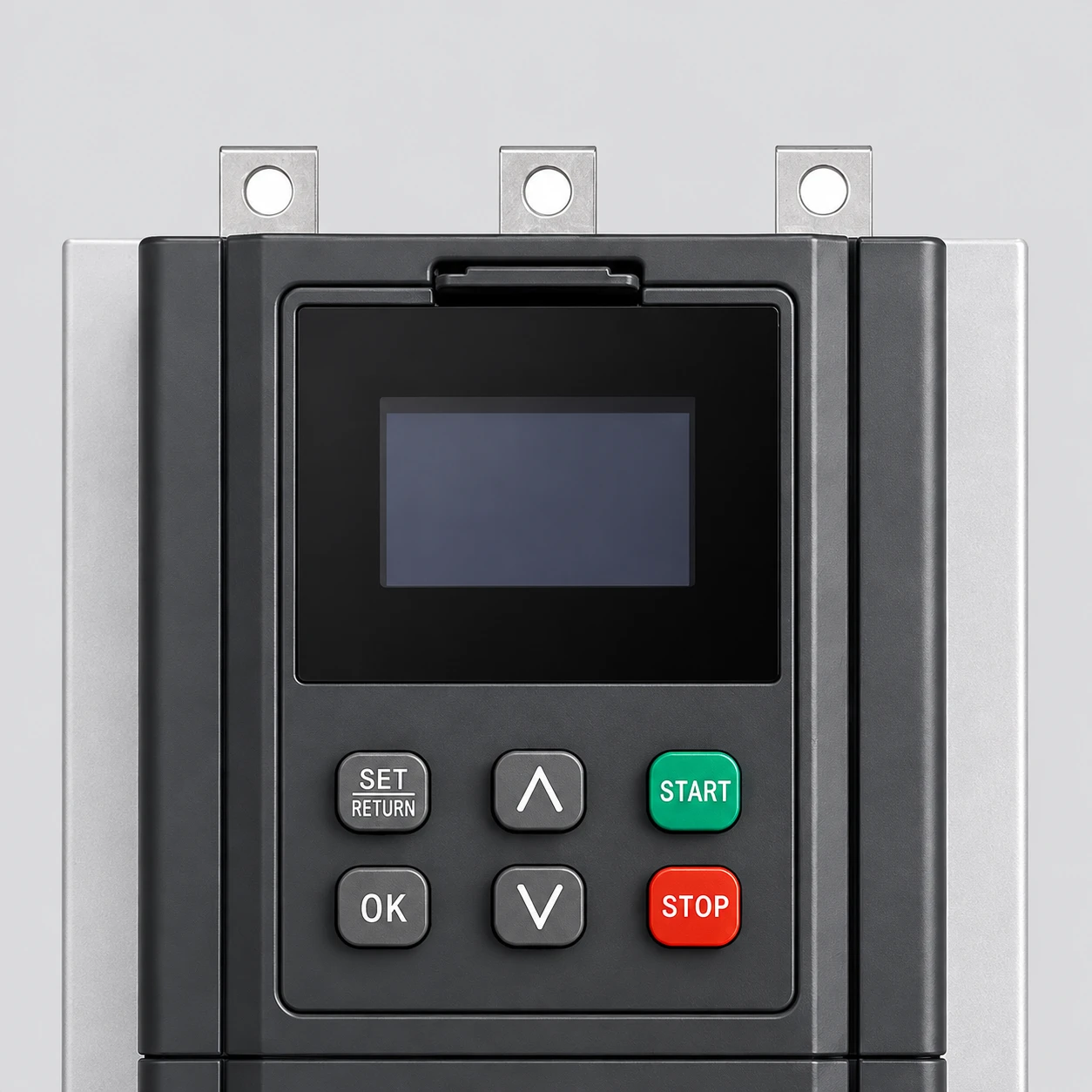
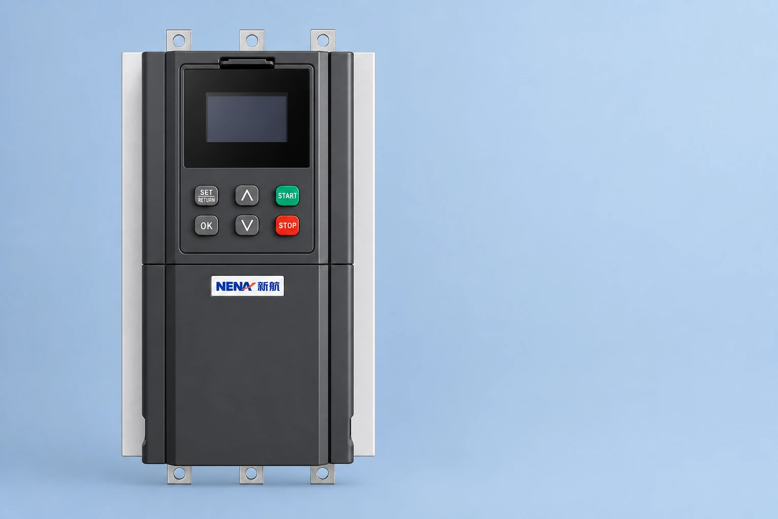
The NENA soft starter for water pump motors is a relevant product reference for a pump-starting discussion. Request the exact model manual and duty confirmation before choosing settings. The illustrations preserve the website product’s visible construction; they do not show a commissioned installation or certify a parameter value.
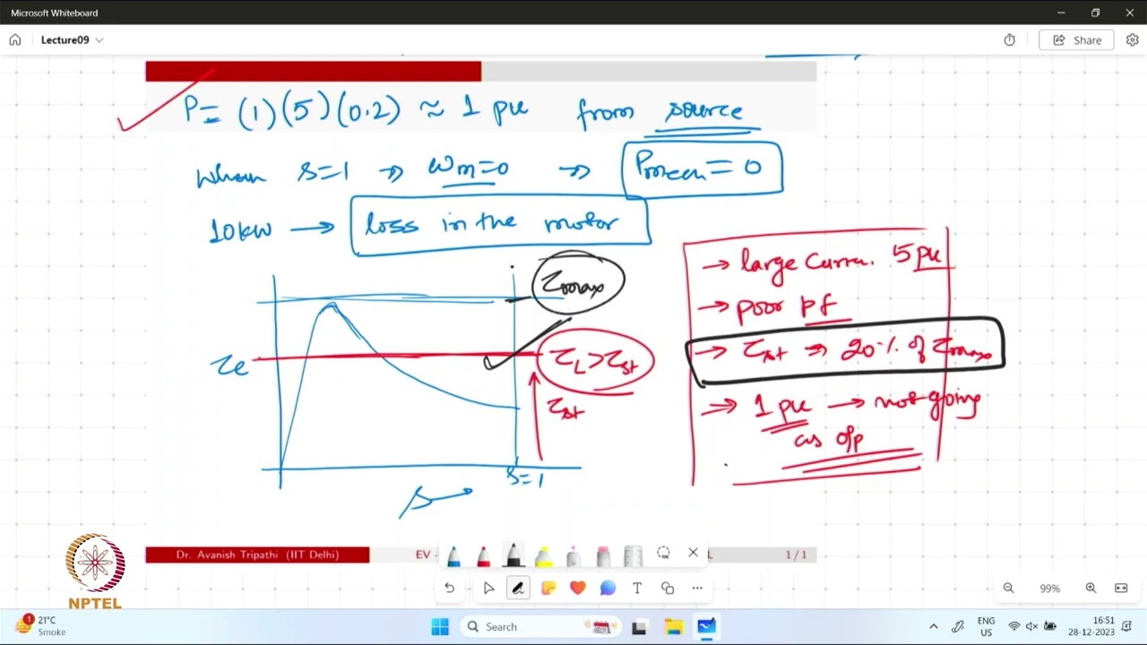
This NPTEL IIT Delhi lecture provides background on induction-motor starting. It supports understanding of the motor behavior; use the supplied NENA manual for the actual controller’s parameter definitions.
Watch on YouTube — NPTEL IIT Delhi
Not necessarily. A voltage ramp describes a controller command, while actual acceleration depends on motor torque, load, inertia and current limiting. Confirm how the selected model and mode define the parameter.
No. Too little accelerating torque can prolong the start or prevent successful acceleration. Evaluate the mechanical result and thermal duty together rather than maximizing the time setting.
The resisting torque and sometimes the effective starting conditions change. A parameter set demonstrated on an empty machine must be checked against the intended loaded duty and hot restart conditions.
No. Equal power labels do not establish equal inertia, load torque, supply conditions, current or starter behavior. Use the actual motor and machine information to confirm the settings.