Capacitor bank current imbalance means the measured currents do not match the pattern expected for that bank, connection and operating state. It can arise from a missing branch, unequal capacitance, an incomplete switching operation, an unbalanced supply or a measurement problem. An unequal reading alone does not identify a failed capacitor. Start by recording which stages are connected, where the currents are measured and what changed before the alarm. Then have a qualified person compare the evidence with the actual circuit and manufacturer instructions. Do not repeatedly reset protection or open an energized cabinet to investigate.
This guide concerns fault investigation and the information an industrial owner should collect. It is not a relay-setting procedure. Low-voltage power-factor correction panels and high-voltage substation banks have different connections, protection and work requirements. A setting or test arrangement taken from one cannot establish a safe limit for the other.
A report saying “phase B is low” needs a measurement boundary. Was the reading taken at the factory incoming supply, at the compensation cabinet feeder, at one switched stage, or at a protection relay input? The incoming current combines loads and compensation; it cannot be treated as the current of one capacitor stage. A controller’s stage command also does not prove that every pole has completed its operation.
Write the boundary directly on the drawing used for the investigation. Identify the instrument, its channel names and whether it reports fundamental current, total RMS current or a calculated quantity. A dashboard number without this context may lead the maintenance team toward the wrong component. Preserve the original screenshot and timestamp before anyone changes scaling or channel assignments.
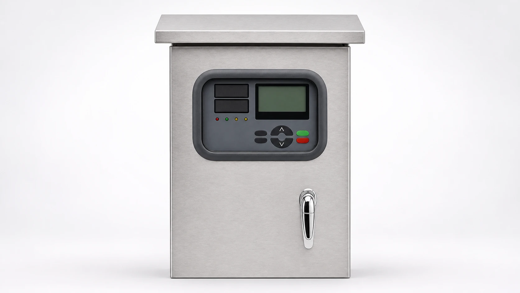
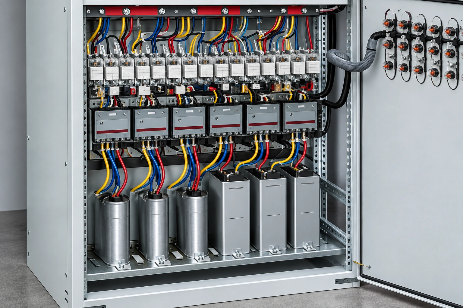
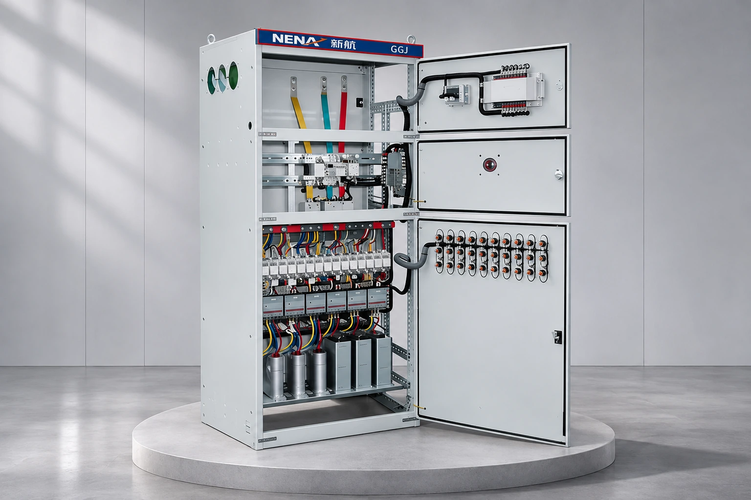
The NENA GGJ compensation cabinet is the relevant product family for this discussion. Its website photograph establishes a cabinet with switching equipment and capacitor components, but it does not establish the bank connection, individual stage ratings or an installed unbalance relay. Those details must come from the supplied drawings and order documentation.
Automatic compensation equipment changes state as the load changes. Comparing three readings captured during different switching states can create an apparent fault. Record the active stage list beside each set of current and voltage values. Where existing monitoring permits, use readings collected at the same time rather than a sequence that spans a stage operation.
If the site has baseline records, compare the suspect stage with its own earlier behavior at a similar voltage and operating state. Do not assume two stages have the same design simply because their contactors look alike. A panel may contain different stage sizes. A useful comparison is one supported by the stage schedule, not by cabinet appearance.
Keep three questions separate in the work order: did the controller request the stage, did the switching device reach its intended state, and did the electrical branch respond as expected? This creates a clear route from the operator’s observation to the electrician’s inspection without asking the operator to perform live measurements.
| Observed pattern | What it may justify checking | Evidence to retain |
|---|---|---|
| One stage changes the phase pattern | That stage’s circuit, switching and component condition | Stage identifier, command and measured response |
| Several stages show the same difference | Common supply conditions or shared measurement channels | Simultaneous voltage record and instrument configuration |
| Local and remote readings disagree | Scaling, phase mapping and data processing | Instrument source register and dashboard value |
| Alarm follows a switching event | Event duration, completed switching and protection response | Time-aligned event log and actual relay indication |
| Abnormal heat, smell or repeated trips | Safe withdrawal and equipment-specific inspection | Alarm history and externally observable condition |
This is a qualitative triage table, not a set of operating permissions. The appropriate response depends on the equipment’s protection study and maintenance instructions. It helps the owner describe a problem precisely while keeping the inspection under qualified control.
Phase-current comparison and neutral-unbalance protection are not interchangeable measurements. A neutral measurement only has the meaning assigned by the actual circuit and sensing arrangement. Before interpreting an alarm, identify the bank connection and the protection function that produced it. Ask for the element name and event record, rather than relying on the general label “capacitor fault.”
A technical statement hosted by FERC discusses harmonic influence on a grounded-wye capacitor-bank neutral protection scheme. Its useful lesson here is that the measured signal and protection design affect interpretation. It is a specific high-voltage system discussion, not a universal threshold or a reason to disable low-voltage panel protection.
Maintain the distinction between diagnosing an alarm and deciding a relay setting. If a proposed repair includes a setting change, require the responsible engineer to identify the calculation, equipment limits and approved revision. A nuisance-trip explanation without supporting records is not enough to justify increasing a threshold.
A de-energized inspection can examine the circuit against its drawing, including protective devices, switching poles, terminations and capacitor identification. The inspection plan should state which observations and tests will distinguish the competing explanations. Replacing parts at random destroys useful evidence and can leave the original supply or sensing problem unresolved.
Capacitors introduce stored-energy considerations after the supply is disconnected. Use the equipment-specific discharge, verification and grounding procedure where applicable. A controller showing zero current is not a verification of the condition at every capacitor terminal. The HSE guidance on safe working practices provides the wider framework for planning electrical work and establishing the required safe conditions.
Record each removed component’s original position and identification before disposal. Retain the test result, the instrument used and the acceptance basis. If a protective device has operated, the investigation should establish why it operated before a replacement is installed. Match replacement suitability to the complete application and manufacturer instructions rather than to physical size alone.
A repair is easier to defend when the acceptance record is agreed before power returns. Define who authorizes energization, which normal operating states need observation, how protection indications will be checked and what condition requires stopping the trial. Use the site’s controlled switching and test procedures. Do not improvise a sequence from an online troubleshooting article.
Austin Energy’s commissioning documentation demonstrates the importance of recording electrical quantities, protection responses and remote indications as part of a controlled handover. Its utility-specific commands and relay arrangements are not instructions for a GGJ panel; the transferable practice is an identified, witnessed and documented acceptance process.
In the final report, link the initial symptom to the confirmed cause and the specific corrective work. Include any unresolved limitations, such as missing historical trends or an inaccessible branch. State whether the evidence covers every stage or only the repaired one. This avoids turning a successful limited trial into an unsupported claim about the entire installation.
Provide the cabinet serial identification, approved single-line diagram, stage schedule, alarm text, time history and relevant instrument configuration. Explain whether the problem appeared after an outage, component replacement, new production load or change in the compensation sequence. Add photographs already available from a safe inspection; do not request photographs that require opening energized equipment.
For the wider system context, see the power-factor correction panel sizing guide. Repeated stage operations are addressed separately in capacitor bank hunting, while the detuned-reactor discussion explains why harmonic considerations belong in the design review. Neither topic replaces investigation of a phase-specific current discrepancy.
If one instrument reports a change and another does not, preserve both records and compare their timestamps and measurement boundaries. Ask whether either value is averaged over a longer interval. Also identify whether a stage switched during that interval. These checks can explain why apparently contradictory reports were both accurate descriptions of different conditions.
For an external service team, create one evidence folder containing the unchanged original records and a separate interpretation note. Mark assumptions as assumptions. A report that says “suspect branch B, not yet confirmed” is more useful than a premature failure diagnosis. Agree what additional evidence would confirm or reject that suspicion before authorizing component replacement. This keeps the outage scope focused and gives purchasing a defensible reason for the requested parts.
The IIT Roorkee lecture below introduces capacitor-bank applications and modeling. It provides background for discussing the circuit with an engineer. It does not provide a troubleshooting limit, an approved protection setting or a live-work method for the installation described here.
Watch on YouTube — IIT Roorkee July 2018
No. The readings must be interpreted against the bank connection, active stages, supply conditions and measurement method. A component failure is one possible explanation that requires confirmation.
No. An overall power-factor value describes a different quantity and measurement boundary. It does not establish that every phase and switched branch is operating correctly.
Only an approved engineering review can justify a protection-setting change. Preserve the event records and investigate the cause before changing the protection response.
Collect a timestamped set of readings with the measurement location, instrument mode, active stages and exact alarm indication. This gives the service team a defined condition to investigate.