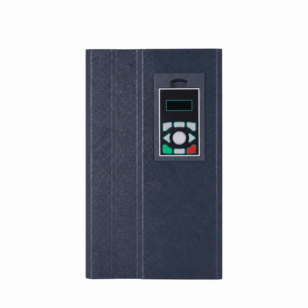
Capacitor bank hunting is repeated switching of correction steps when the load has not changed enough to justify it. Before increasing a delay or replacing a controller, compare the measured reactive demand with the smallest step, confirm the current transformer arrangement, and check the controller’s actual programmed step sequence. An unstable power factor display alone does not establish the cause. This guide helps a buyer or maintenance manager collect useful evidence for a qualified engineer; settings, isolation and tests must follow the particular bank’s documentation and the site’s electrical safety procedure.
A bank may add and remove steps during normal production changes. A compressor stopping, a process line starting, or a bus transfer can produce a legitimate response. Hunting describes a less useful cycle: a step enters, the controller reverses its decision, the same correction leaves, and the pattern repeats without a matching change in demand. Record the step indicators and load together rather than counting contactor sounds from outside a closed room.
Ask when the pattern began. A new installation that has never controlled correctly suggests a commissioning issue. A previously stable bank that starts cycling after a transformer change, new generation, or production modification deserves a fresh system review. A fault limited to one stage may point toward stage feedback or equipment condition. These are investigation branches, not proof that any one component has failed.
Keep this issue separate from the initial calculation of total compensation. The power factor correction panel sizing guide addresses required capacity. This article concerns how an installed automatic bank behaves as demand changes, particularly at low load. A correctly calculated total rating can still have an unsuitable step arrangement for overnight operation.
Request a time record covering one stable production interval and one light-load interval. Useful fields include real power, reactive power, power factor with its leading or lagging indication, controller demand, connected stages, alarm status and the operating state of major loads. Use time-aligned records where possible. Readings copied from different minutes can suggest oscillation that never actually occurred.
Write down where each measurement originates. A utility meter, a power quality recorder and a controller can observe different electrical boundaries or use different averaging periods. A disagreement does not automatically mean a failed instrument. The reviewer needs the one-line diagram and measurement locations before deciding which value describes the bank’s controlled point.
The university-hosted Electrical Energy Conservation and Auditing reference discusses automatic correction, low-load behavior, deadband and discharge-related timing. Use those concepts to frame questions; it does not supply a universal setting for every controller or installation.
| Observed pattern | Evidence to request | Question for the engineer |
|---|---|---|
| Repeated cycling during a steady light load | Reactive demand and actual smallest connected step | Does one step overshoot the useful correction range? |
| Controller response appears opposite to demand | Approved sensing diagram, polarity and phase references | Does the controller receive the intended system measurement? |
| One indicated stage has little measured effect | Stage current, alarms and isolated inspection findings | Is the commanded stage actually available? |
| Cycling begins after a bus transfer | Open and closed tie configurations with sensing boundaries | Does the control scheme remain valid in this operating mode? |
| Behavior changes after a setting edit | Previous and current setting exports | Which change altered step selection or timing? |
This is an evidence checklist rather than a repair sequence. The rows combine distinct possible causes; a qualified reviewer must decide which applies to the measured installation. Stop routine operation and follow the site’s response procedure if there is abnormal heating, smoke, damage or other evidence of danger.
The current transformer ratio, phase association and sensing location should match the controller design. Obtain the approved arrangement rather than assuming that a photograph of another bank is a suitable wiring reference. A multi-source board, separate load feeder or bus coupler can make the measurement boundary more complicated than a single incoming supply.
Do not instruct an operator to reverse CT leads as an experiment. CT circuits need an approved safe method; disturbing an energized secondary can create a dangerous condition. Ask the engineer to document the finding and the controlled verification method. A purchasing checklist can require correct sensing without presenting hands-on electrical work as a general reader task.
Distinguish the displayed ratio from physical installation evidence. An export can show that a number was entered, while drawings and commissioning records show what is installed. If those disagree, resolve the discrepancy before using trends to justify larger stages or faster switching. Retain both the original export and the corrected record.
Total bank capacity tells only part of the story. A plant may need substantial correction with several motors loaded but very little after production stops. If the first usable stage is too coarse for the remaining demand, the controller may have difficulty settling within the intended control range. The engineer should compare real stage output and the measured reactive demand across the actual operating envelope.
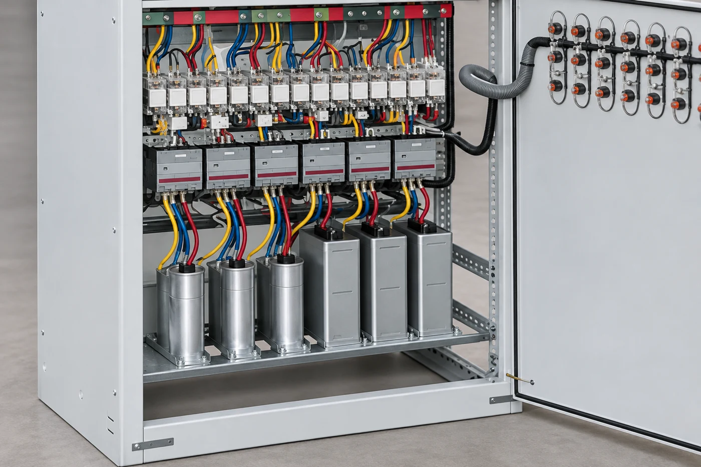
Do not assume that every stage has the same rating or that the controller discovers the sequence automatically. Record which stages are fitted, enabled, healthy and available. A failed small stage can leave the controller choosing between larger increments even though the original design had adequate resolution. That calls for condition assessment before redesign.
A target should also match the supply agreement and site operating policy. Moving the target close to unity may reduce tolerance for changing demand; changing it simply to stop an alarm can hide another issue. Ask for the reasoning and acceptance range in the commissioning report. Neither an arbitrary target nor a borrowed default proves satisfactory control.
A delay can prevent a controller from reacting to every brief fluctuation, but there are several different timing functions. The controller may distinguish connection delay, disconnection delay, stage reuse restriction, measurement averaging and alarm delay. Identify which parameter is being discussed and whether it applies to an individual stage or the whole bank.
The installed capacitor and switching equipment determine the permitted return-to-service conditions. Do not shorten a discharge-related restriction because the power factor display looks slow. Conversely, extending every delay can make the bank miss meaningful load changes. Require the proposed timing to be checked against component documentation and the plant’s recorded demand pattern.
For the electrical work itself, HSE safe working practices provides the broader planning and competence framework. Isolation, stored energy and confirmation of a safe condition belong in the work procedure. A controller screen showing no connected steps does not establish that a cabinet is safe to access.
Repeated commands and repeated physical operation are different findings. A relay output might change correctly while a contactor or stage fails to respond. Conversely, a controller may command unnecessary changes even though every stage works. Ask the service report to show command, response and measured effect separately. That distinction prevents replacing a controller simply because contactors are noisy.
Where the installation includes substantial electronic loads, request a power quality review before adding capacitors or changing the stage design. Harmonic conditions and resonance require a different assessment from ordinary correction control. A hunting complaint is not sufficient evidence that a detuned bank is necessary, and a detuned label is not proof that sensing or timing is correct.
Changes to pumping equipment can alter the daily load pattern. The duplex pump alternation guide helps explain changing pump duty, while the starts-per-hour checklist addresses repeated motor operation. These articles describe load behavior rather than replacing a compensation study.
Specify representative operating conditions before testing: normal production, low demand, a planned major load transition and any approved alternative supply mode. For each condition, state which readings will be recorded, how long observation will last and what constitutes unnecessary switching. The duration should capture the actual process cycle rather than use an unsupported universal number.
Change one documented cause at a time where practical. Save the starting settings, identify the authorized edit, record the result and explain why the final configuration is acceptable. If multiple changes are necessary together, list them explicitly. A report saying “adjusted parameters, now normal” gives the next engineer little help when the operating pattern changes again.
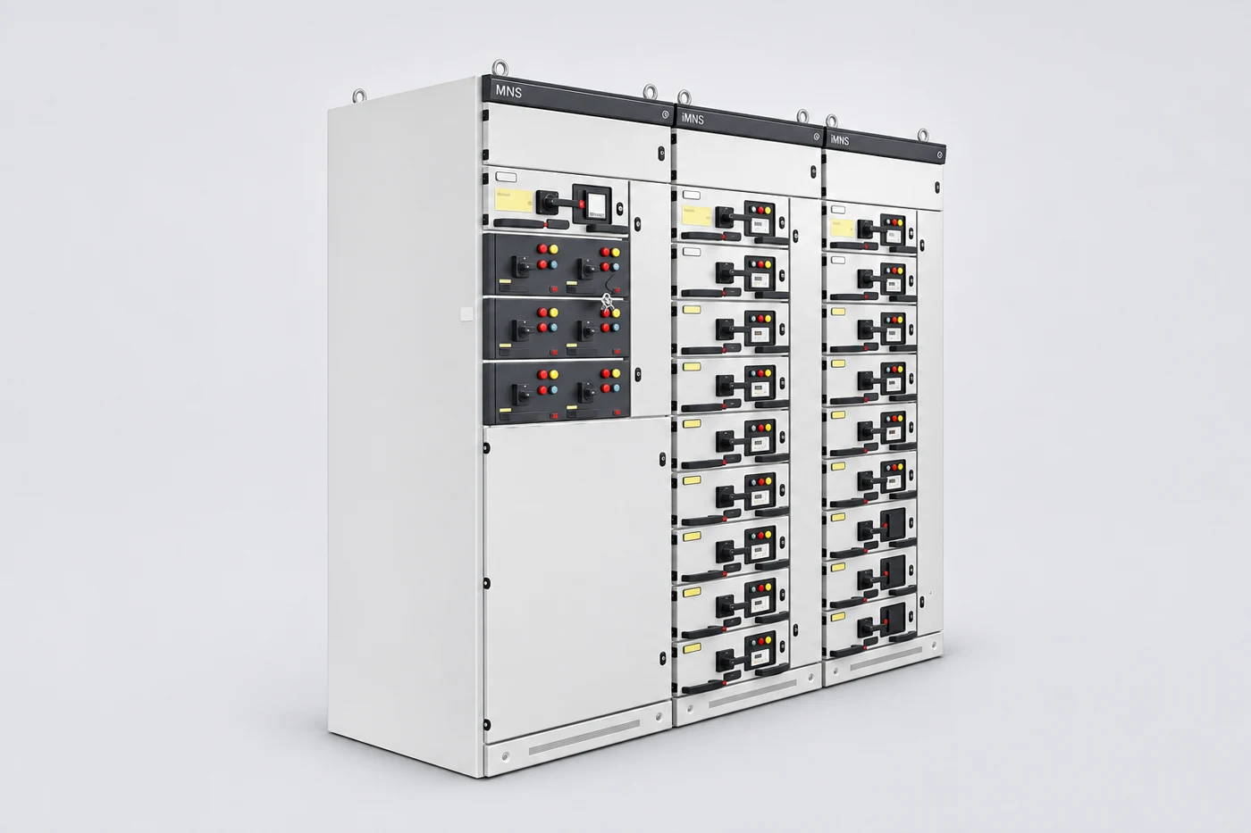
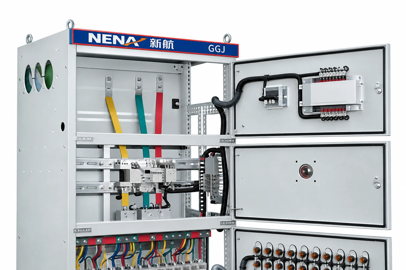
For a new GGJ compensation cabinet enquiry, provide the one-line diagram, load trend, existing stage ratings, sensing arrangement and known power quality information. Ask the supplier to confirm the proposed controller, stage sequence and supporting documentation. The cabinet photograph illustrates the product family; it does not establish the supplied controller functions or the suitability of a specific configuration.
The following educational lecture explains the electrical background of power factor correction. It supports understanding of reactive demand; it is not a commissioning procedure for a GGJ cabinet. Use the installed controller manual and the approved test plan for field decisions.
No. First compare the switching timeline with actual load changes. Repeated add-remove cycles during a stable load are more suggestive of hunting than switching that follows genuine production changes.
No. Identify the particular timing function and the cause of the response. Discharge and stage reuse restrictions must remain consistent with the installed equipment documentation.
It can reduce the useful correction choices available to the controller. Confirm commanded state, actual stage condition and measured effect before deciding whether the design needs different step sizes.
Send the one-line diagram, controller model and settings, stage ratings, alarms, recent modifications and a time-aligned record of demand and stage operation during the problem.