A soft starter emergency stop must be designed as part of the machine’s safety system. The ordinary stop command, a soft-stop ramp and maintenance isolation serve different purposes. Do not assume that a red keypad button or a stopped motor provides an emergency-stop function or makes the motor circuit safe to work on. Start with the hazards, required stopping behavior and exact equipment documentation, then have a competent designer specify and validate the complete system. This guide helps purchasers ask the right questions without copying an unverified wiring arrangement into a working machine.
A machine can present more than one hazard when it stops. Consider the driven equipment, stored energy and any associated process. Removing a run command may allow a load to coast; a controlled stopping function may depend on power and equipment capability. The responsible designer must decide which response is appropriate. There is no universal emergency-stop setting that can be selected from motor power alone.
Write down what should happen when the emergency control is operated. Identify which equipment must stop, which process functions must remain available and how the achieved state will be confirmed. Keep normal production shutdown separate from the emergency response. A gentle shutdown chosen to protect a process may not address the hazard that requires urgent intervention.
The HSE work equipment guidance discusses emergency controls and their relationship to other safeguards. Its legal context is Great Britain; use it as a reference while applying the requirements for the actual machine and jurisdiction. An emergency stop does not replace the risk assessment or necessary guarding.
| Function | Main purpose | Evidence to request |
|---|---|---|
| Normal stop or soft stop | End normal operation with the intended process behavior | Documented control function and commissioning result |
| Emergency stop | Achieve the risk-assessed response to an emergency | Safety-system design, defined behavior and validation record |
| Maintenance isolation | Control relevant energy sources for the work | Equipment-specific isolation method and required verification |
The comparison follows the distinction between operating controls and work preparation in the HSE references. It does not assign a safety category or performance level to a NENA product. Those claims require documentation for the complete installed arrangement.
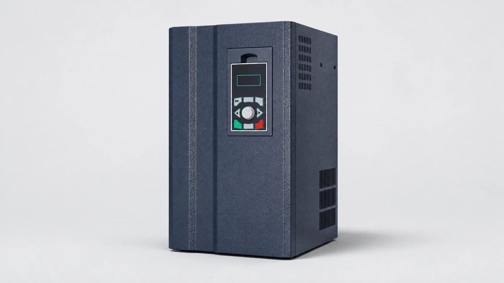
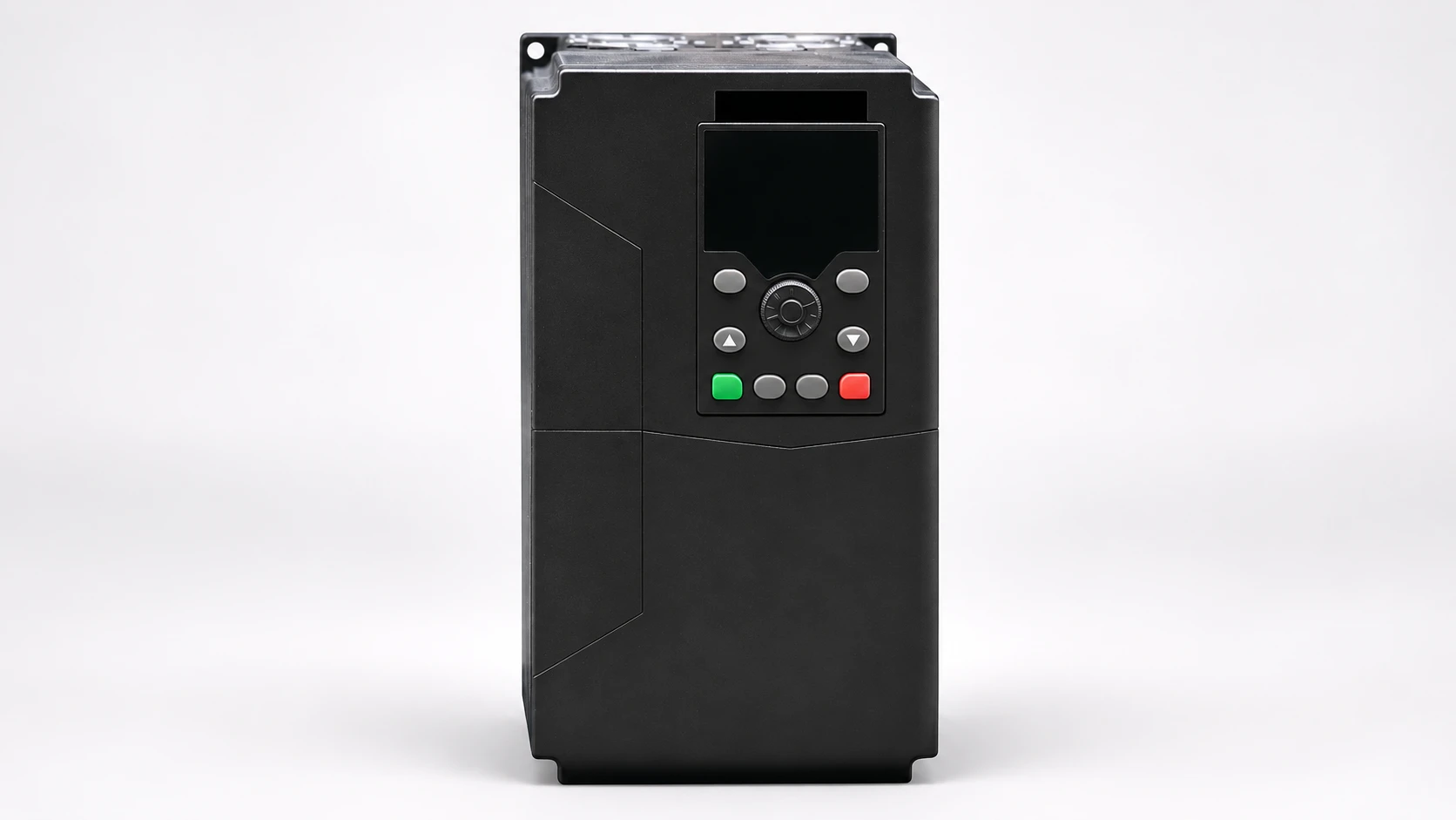
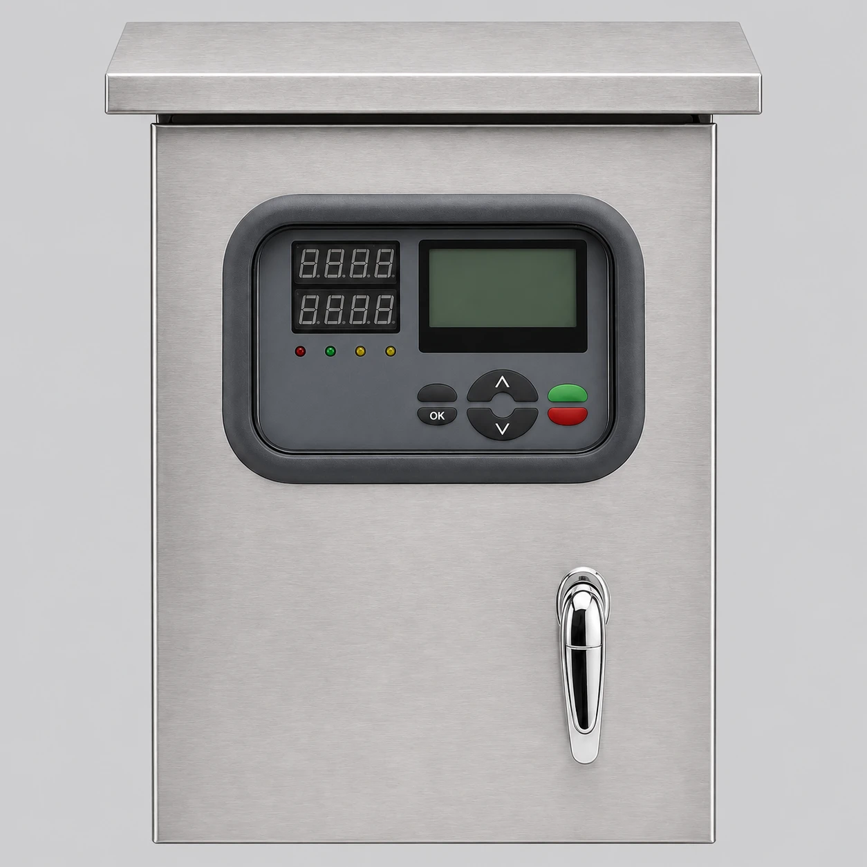
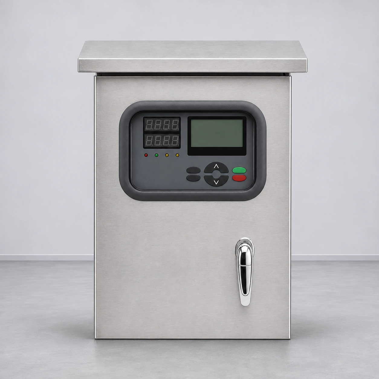
A keypad is an operating interface. The color or wording on a button does not show how the downstream circuit behaves, what faults have been considered or whether the function has been validated for the machine’s hazards. A stop command can be useful for normal operation without being the safety function required by the risk assessment.
Ask the supplier to identify the exact command path and the equipment that performs the required action. A drawing should distinguish the operator control, logic, final switching elements and feedback where applicable. A general marketing statement that the starter has protection features does not answer those questions. Motor overload protection and emergency stopping address different problems.
Do not test a suspected safety function by introducing a real hazardous condition. Arrange an approved validation plan with the responsible personnel. The plan should state the expected response, safe test conditions and how results will be recorded. A motor stopping once after a button is pressed is an observation, not a complete validation record.
A soft-stop function changes the way a suitable load stops under defined operating conditions. It should not be assumed to provide a braking action or a guaranteed stop time. The relationship between electrical control and actual shaft motion depends on the motor, load and process. Obtain the exact manual and discuss the required behavior with the supplier.
For a pump, stopping behavior can interact with hydraulic conditions. For another machine, the load may coast or be driven by the process after the starter has stopped supplying it. The risk assessment should consider the actual behavior. Changing a ramp to improve one process symptom does not establish that the emergency response remains satisfactory.
The soft starter ramp-time guide addresses normal operating adjustments. Use that topic separately from the safety-system review. If a parameter change can affect the validated behavior, manage the change through the responsible designer and repeat the appropriate checks rather than treating it as a routine operator preference.
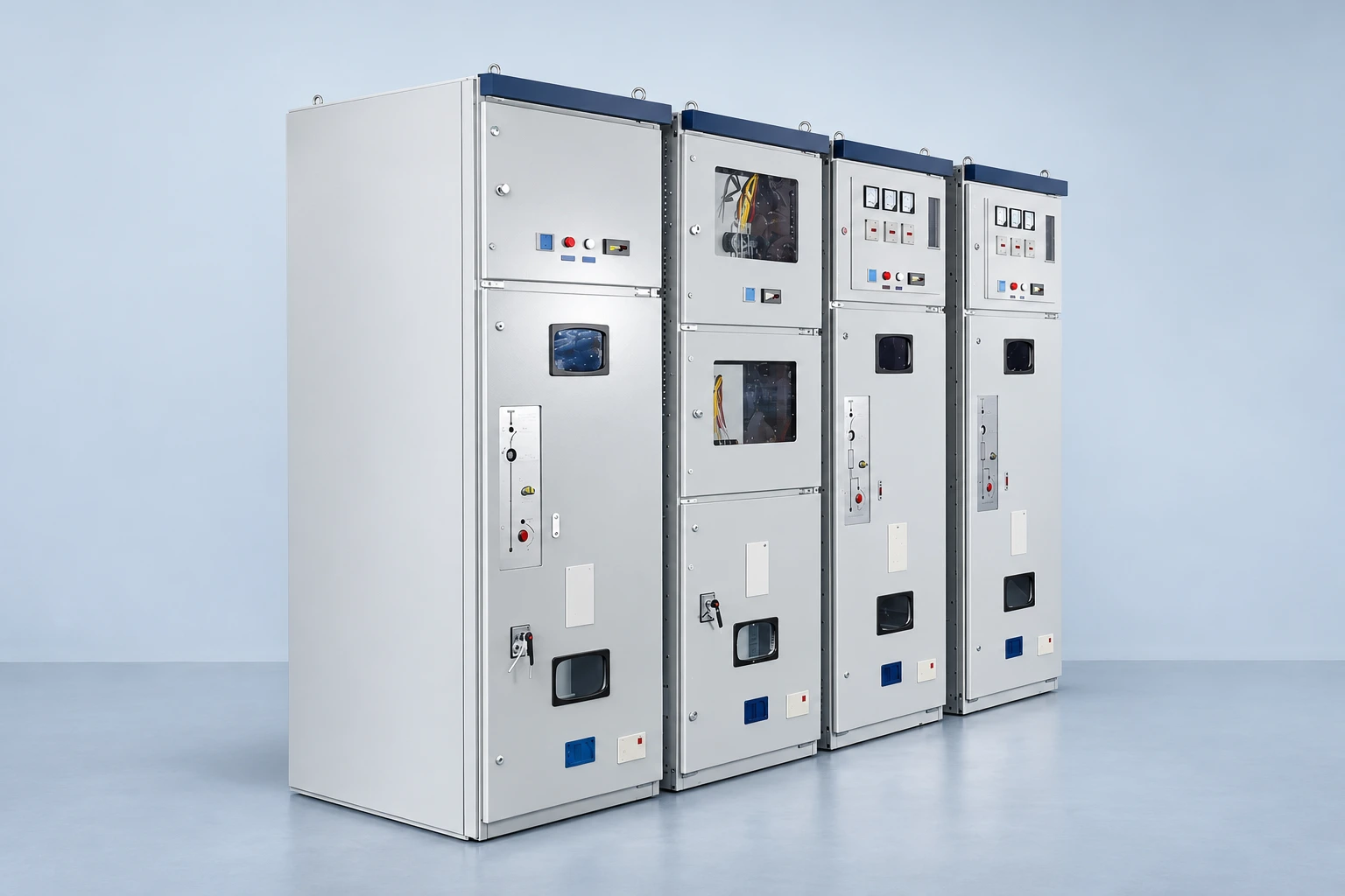
A starter cabinet can contain more than the electronic starter. Bypass devices, control supplies, protection and external interfaces can affect the circuit state. The emergency response must account for the actual arrangement throughout operation. A function that appears effective during starting may need different consideration when the motor is running through a bypass path.
Do not infer that a particular contactor provides isolation because its name includes “main” or “bypass.” Ask what the device is intended to do and what its documentation establishes. Maintenance isolation requires an appropriate method for the complete work scope; a safety-related stopping function and an isolating function should remain explicitly distinguished.
The bypass contactor failure article discusses a complementary troubleshooting topic. A service fault should be resolved through the approved process before the equipment returns to normal operation. Repeatedly resetting a fault or bypassing a feedback signal is not a sound way to prove the emergency response.
The HSE electrical safe working guidance provides the basis for planning electrical work, including isolation and verification. A stopped machine can still contain electrical energy, separately supplied controls or mechanical and process energy. Define the task and identify the relevant sources before deciding how work can proceed.
Keep the work location precise. Work on an external operator station, on the starter terminals and on the driven machine can have different boundaries. If the job expands, reassess the plan. The fact that an emergency-stop control has been operated does not authorize opening a cabinet or handling a motor connection.
Coordinate the electrical team with the process owner. A pump, fan or conveyor can be affected by conditions outside the starter cabinet. Document who controls those conditions and how they will remain controlled. Good records prevent one team from assuming that another has already addressed an energy source that was never included in the work plan.
Describe what happens after an emergency control is released or reset. The design should make the intended relationship between reset, permissives and a new start command clear. Confirm the applicable requirements through the machine’s safety assessment. Do not accept an ambiguous statement that the machine “returns to normal” without identifying what starts and under which conditions.
Review remote and automatic commands as part of that discussion. A machine can receive a demand from a controller, level input or supervisory system. The designer needs to account for these commands in the complete behavior. An operator standing at the cabinet may not know that a remote demand is still present.
Record approved settings and drawing revisions at handover. If a later modification changes a control mode or restart behavior, evaluate its effect on the safety system. A useful change record explains both the operational reason and the checks performed, so future staff can distinguish an authorized change from an unexplained parameter difference.
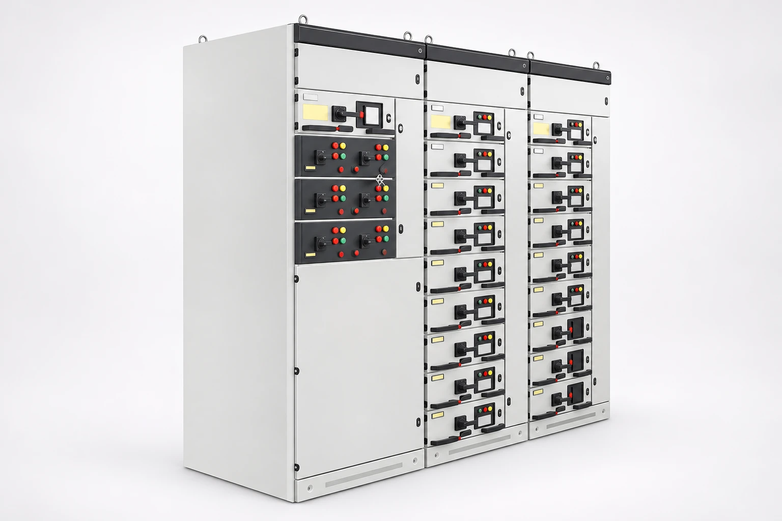
NENA offers an NR1000 stainless steel soft starter cabinet. Request the actual main and auxiliary circuit drawings, device list, operating instructions and any relevant function documentation for the proposed supply. The exterior illustration does not establish an emergency-stop circuit, an isolation arrangement or a safety certification.
Provide the machine description, motor data, load behavior, operating modes and risk-assessed stopping requirement. State who is responsible for integrating and validating the complete machine. The broader soft starter overview explains its normal motor-starting role; use that background without treating the starter alone as the machine’s complete safety system.
A quotation should make the boundary of supply clear. Identify whether the supplier provides only the starter cabinet, a proposed control design or a complete validated machine function. Assign responsibility for external devices, installation and final testing. Otherwise each party can assume that another party is completing the safety integration.
Ask for the documents early enough for the machine designer to review them. A drawing delivered after the cabinet arrives can reveal missing interfaces when changes are costly. Resolving those questions during specification gives the final validation a clear design to check.
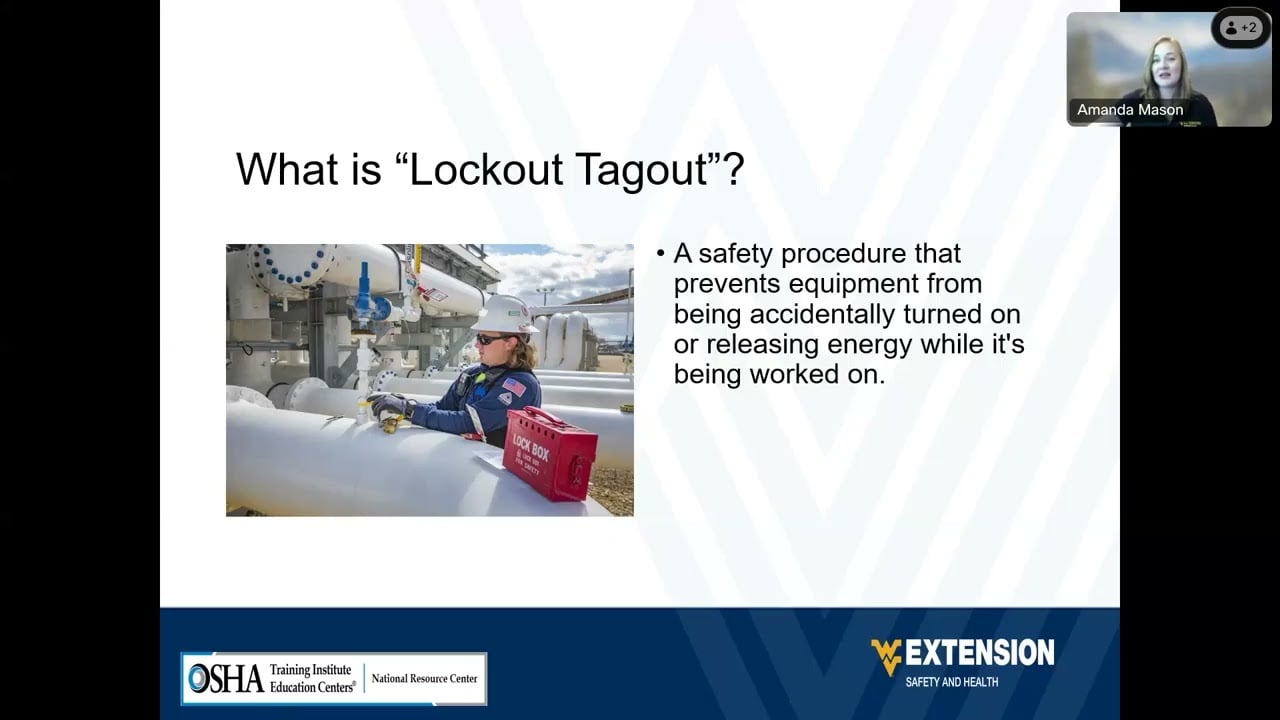
The Department of Labor educational video below explains hazardous-energy control. It is included to reinforce the maintenance boundary, not as a wiring guide for the cabinet or a substitute for the machine’s validated emergency-stop design.
Watch on YouTube — USDepartmentofLabor
Do not assume so. The emergency response must follow the machine’s risk assessment and validated safety-system design.
No isolation claim follows from button color. Use the equipment-specific isolation method and required verification for maintenance.
Yes. The complete circuit and all operating states must be considered. Obtain the actual drawings rather than assuming the electronic starter controls every path.
The responsible machine and safety-system designers should assess it, update documentation and define the checks needed before release.