A soft starter phase loss fault means the controller has detected a condition that meets its model-specific phase monitoring rules. It does not, by itself, prove that the incoming utility has lost a phase. The investigation may involve the incoming circuit, switching devices, motor circuit, sensing arrangement or the starter itself. Preserve the exact alarm and its timing, prevent unintended restart, and have a qualified person compare the installation with the correct manual before changing protection settings. This guide focuses on building that evidence rather than prescribing live electrical tests.
Record the displayed code exactly, including any suffix, and save the event history before clearing it. Two starter families can use similar words for different detection rules. A general “phase fault” description from an operator is useful for opening a service case, but it is not sufficient for choosing a replacement part or changing a threshold.
Next record when the alarm occurs: before a start command, immediately after the command, during acceleration, at transfer to bypass, or after normal running. The sequence helps the service engineer separate availability of supply from changes in the current path. It also helps avoid a broad fault-finding exercise when the symptom is closely associated with one operation.
For the wider process, use the soft starter troubleshooting guide. This page treats phase monitoring as a narrower investigation. A heat alarm, inadequate acceleration or communication failure may require a different branch even if the motor also fails to start.
A stopped motor and a blank display do not prove electrical isolation. Incoming power, separate control power, remote commands and connected equipment must be considered in the site procedure. HSE safe working practices explains the need to plan electrical work, select competent people and establish safe working conditions. The method must be appropriate to the installation and jurisdiction.
The owner can collect external information without opening equipment: the alarm time, process state, motor nameplate photograph already on file, recent work orders and the approved circuit diagram. Internal inspection and electrical measurements belong with the competent service team. Do not ask an unqualified operator to repeat starts while someone observes exposed terminals.
Agree who can authorize a restart and how remote starting is controlled. A successful reset can allow the machine to move unexpectedly if commands remain present. The service plan should cover the driven process as well as electrical equipment, including pump pressure, material movement and access by other workers. An investigation is incomplete if it fixes an alarm but creates an uncontrolled restart condition.
A missing phase and unequal phase voltages are related supply concerns, but they are not interchangeable descriptions. Use a consistent set of measurements and clearly identify the measurement point, operating condition, instrument and time. A reading taken upstream of a switching device does not establish the condition at the motor when that device operates.
The Natural Resources Canada electric motor reference guide discusses why voltage unbalance matters for motor current and heating. That supports checking the actual supply condition. Its general guidance does not establish the phase-loss algorithm or settings of a particular NENA starter.
Avoid borrowing an unbalance limit or phase-loss threshold from an unrelated product. The motor requirements, starter functions, protection devices and site design must be reviewed together. Ask the engineer to state whether a finding concerns absence of voltage, unequal voltage, unequal current or insufficient measured current. Those observations lead to different next questions.
| When the fault appears | Record to collect | Review focus |
|---|---|---|
| Before any start request | Control state, available supply records and exact code | Model-specific pre-start monitoring conditions |
| Immediately on a start request | Command sequence and switching-device state | Whether the intended power path is established |
| During acceleration | Current history, motor details and event timing | Supply behavior, load circuit and documented monitoring rules |
| At bypass transfer | Transfer event, feedback and circuit drawing | Actual bypass path and retained sensing functions |
| After maintenance or motor replacement | Change list and before/after records | Connections, ratings and configuration changes |
The table is a service handover framework. It does not identify a failed component from alarm timing alone. Findings should be checked against the exact manufacturer documentation and the approved electrical design, with safe access and testing arranged by the service team.
The relevant path includes more than the starter enclosure. Ask for the circuit from incoming protection through contactors and the starter to any downstream switching devices and the motor. Show where phase monitoring and current sensing occur. An incomplete drawing can conceal a device whose operating state changes precisely when the alarm appears.
List recent component replacements, including fuses, contactors, cables, terminals and the motor. Record the actual replacement identifiers rather than saying “same type.” A part can appear similar while having a different coil supply, contact arrangement or rating. The service engineer can then decide which differences are relevant without relying on memory.
Where the team finds heat damage or a poor connection, record the evidence and assess the surrounding equipment before return to service. Tightening a connection without checking its condition or the approved method may leave the underlying defect unresolved. Installation torque, replacement decisions and inspection criteria must come from the equipment documentation, not a generic blog value.
A bypass changes the running-current path around the semiconductor power section. Which monitoring and protection functions remain active depends on the starter and the actual circuit. Do not assume that an internal bypass guarantees every desired function or that an external bypass necessarily removes all monitoring. Request the model-specific explanation and wiring arrangement.
If the alarm occurs at transfer, time-align the starter event, command output and available feedback. An event labeled “bypass” may describe a controller command rather than confirmed mechanical contact operation. The engineer needs to distinguish intended action, actual device response and measured electrical result. Replacing a contactor based only on a screen label skips that distinction.
This investigation differs from choosing between starter technologies. The soft starter versus VFD comparison addresses application selection. A VFD is not a general cure for an unresolved phase-related installation fault, and substituting equipment requires a fresh review of the circuit and process.
Save the current configuration and identify the manual revision before making an authorized edit. Useful records include motor rated current, connection arrangement, enabled monitoring, restart behavior and any relevant input assignments. Record whether the file was read from the installed device or copied from an older commissioning package.
Do not lower a monitoring threshold or disable a protection function merely to make a trial start succeed. A nuisance trip and a real fault can look similar from the operator station. Any change needs a documented reason, a check against the motor and circuit requirements, and an agreed method for verifying that protection remains suitable.
Also account for test conditions. An unloaded demonstration, a different motor or a changed connection can affect whether a controller’s monitoring criteria are met. A bench test should state the motor, connection and operating state. Passing an unexplained test does not establish that the original installation is healthy.
A useful service report states the original symptom, evidence collected, identified cause, corrective action and verification result. If the cause remains uncertain, say so. “Reset successfully” describes only an action and an immediate outcome. It does not show why the alarm occurred or whether it can recur under the original process conditions.
The acceptance plan should include the affected operating stage and representative duty, within the documented start limits. Review cooling time and accumulated duty before repeated trials. The starts-per-hour article explains why the number of test starts cannot be separated from thermal duty. Stop testing when the authorized plan or equipment limits require it.
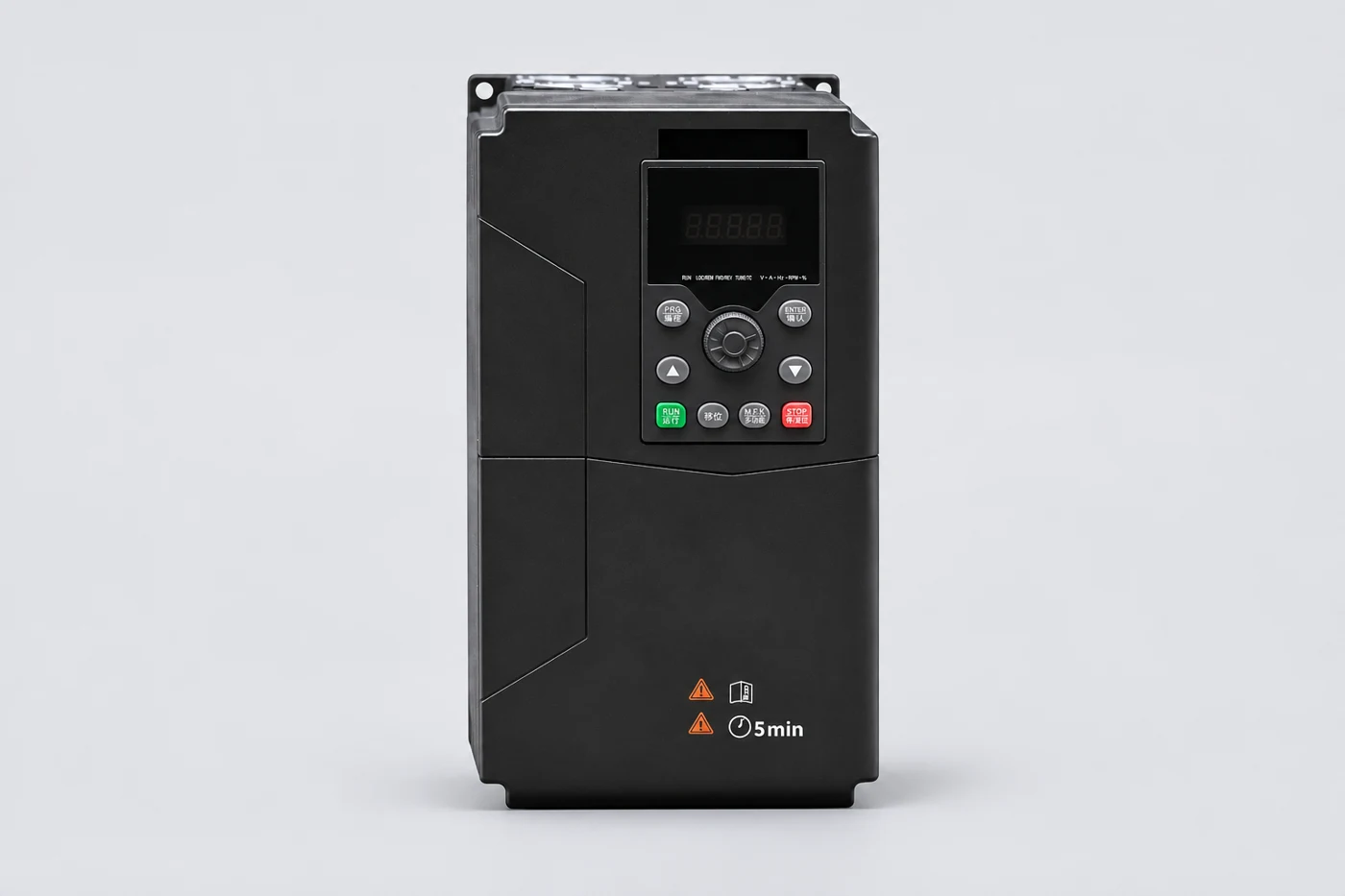
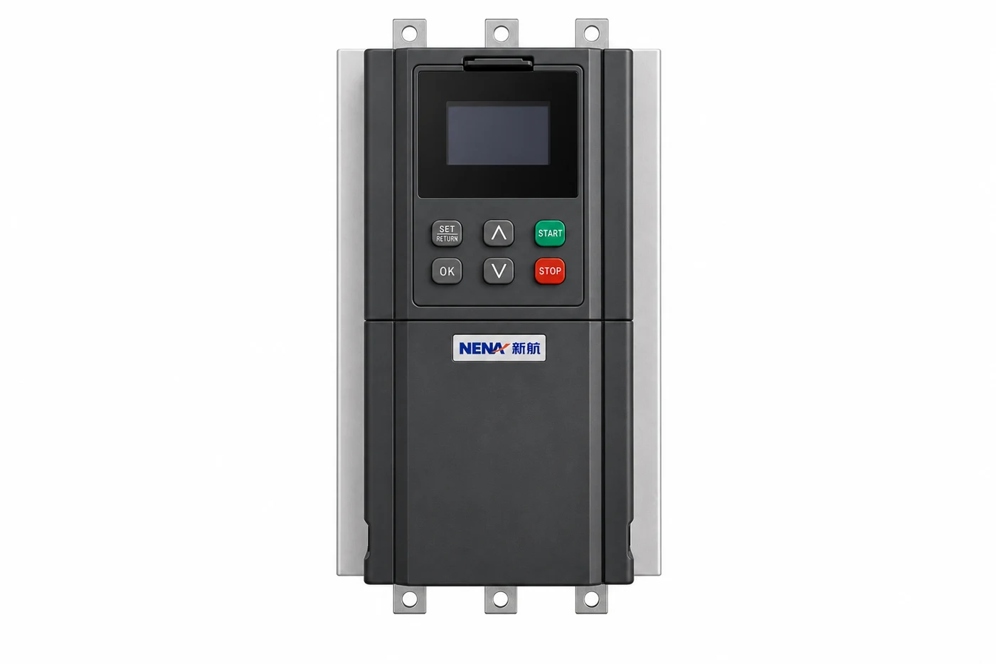
For a replacement or new pump soft starter enquiry, send the motor nameplate, supply details, duty, circuit diagram and fault history. Ask for the exact model manual and confirmed monitoring functions. The pictured product is a family reference; its appearance does not establish phase-loss thresholds, certification or compatibility with an existing cabinet.
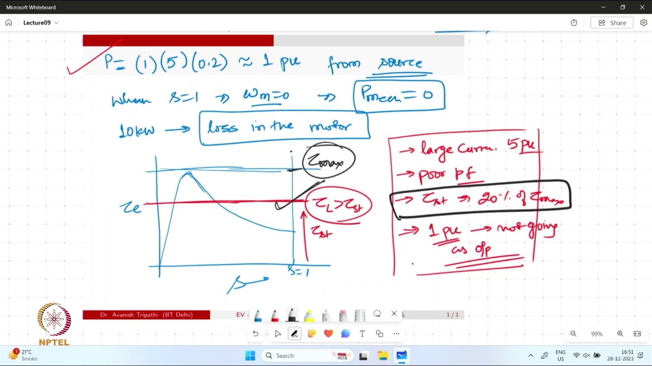
This NPTEL lecture explains induction motor starting and speed control. It provides background for understanding the operating stages in a service record. It does not supply alarm definitions or a repair procedure for the installed starter.
Watch on YouTube — NPTEL IIT Delhi
No. The indication must be interpreted using the starter’s manual and the actual circuit. The relevant condition may involve the incoming supply, motor circuit, switching path or sensing arrangement.
Do not disable protection as a general workaround. A qualified reviewer must identify the cause and approve any configuration change against the equipment and motor requirements.
The current path changes during transfer, so timing helps the engineer compare the command, actual device response and monitoring arrangement. Timing alone does not prove which component has failed.
Provide the exact starter model, alarm code, motor nameplate, operating stage, circuit diagram, settings export, recent changes and the service team’s safely obtained findings.