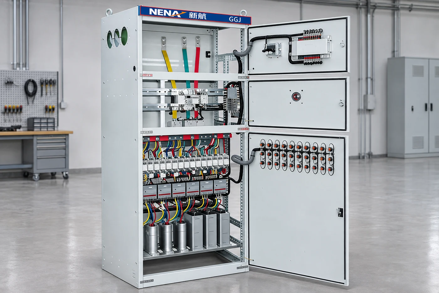
A pump high level alarm means that the monitored liquid level has reached the alarm condition defined for that system, or that the alarm circuit is reporting a condition that needs investigation. It does not by itself prove that the pump motor has failed. The useful first questions are whether the level is genuinely high, whether pumping is removing liquid and whether the alarm reaches the person responsible for responding. This guide explains how to separate process, pump, sensor and notification evidence when reviewing a water or wastewater pump control panel.
Obtain the approved control narrative and identify what each level input is supposed to do. A pump-down sump, a tank filling system and a protective shutoff application can require different responses to a high level. Do not copy the sequence from another site just because the front panels look similar.
For a pump-down arrangement, the alarm may indicate that inflow is exceeding effective removal, that normal starting did not occur or that the level signal is incorrect. For a filling arrangement, a high level may require stopping an incoming pump. The approved design determines the action, the reset behavior and the response priority.
The EPA control panel fact sheet describes high-water alarms alongside pump control and other panel functions. It provides useful background on the role of a panel, but it does not establish which functions are fitted to a particular NENA product or required at every site.
Keep process level, pump command, actual pump operation and alarm delivery separate in the event record. A controller may command a pump without the machine running. A running motor may not deliver the expected flow. An alarm lamp may illuminate locally without notifying a remote operator.
Record the time, system mode, observed level indication and alarm message before clearing anything. Add the available operating status and recent events such as a power interruption, heavy inflow or maintenance work. Use observations that can be collected safely; a high-level event does not justify opening live equipment or entering a tank.
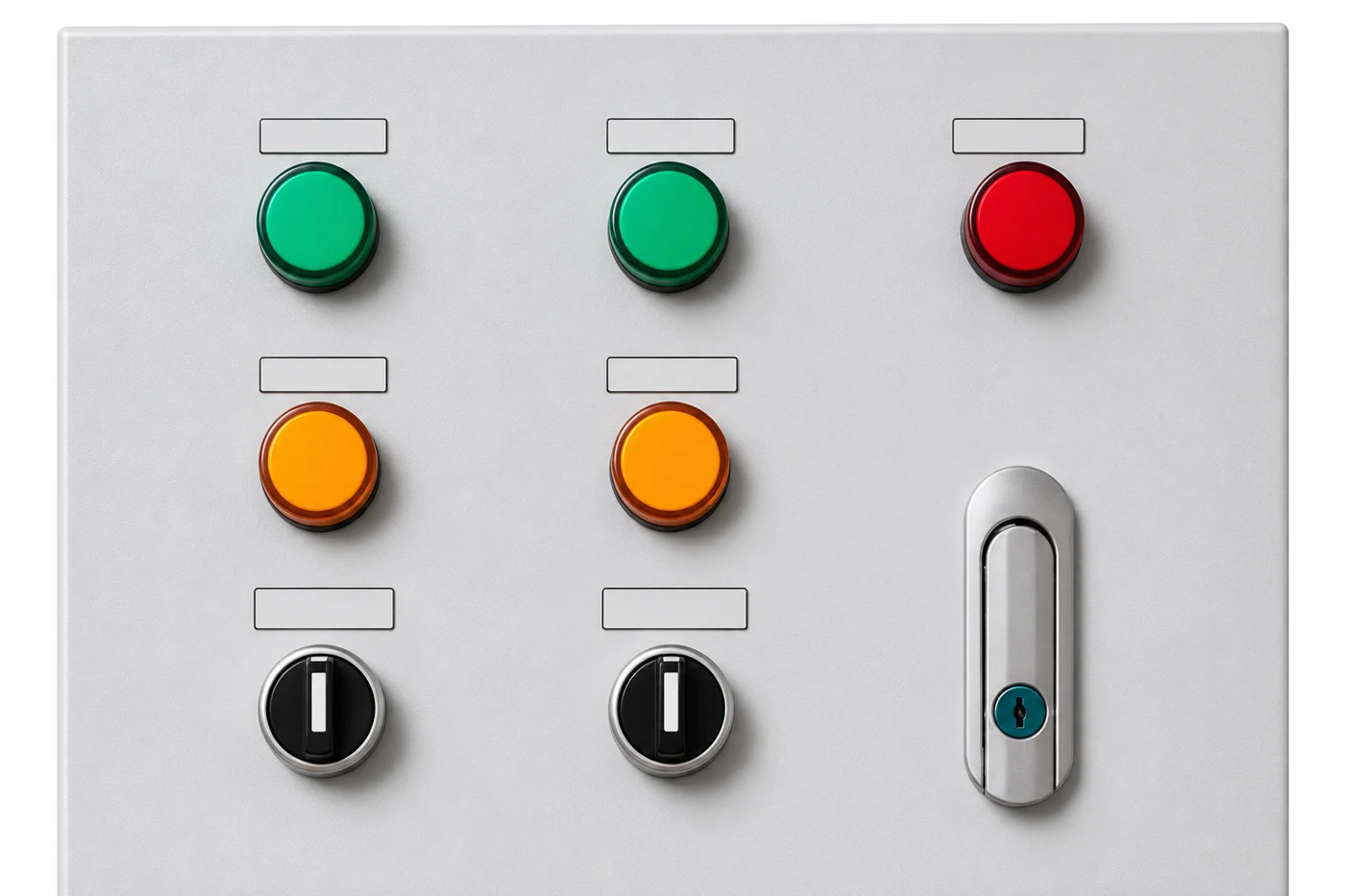
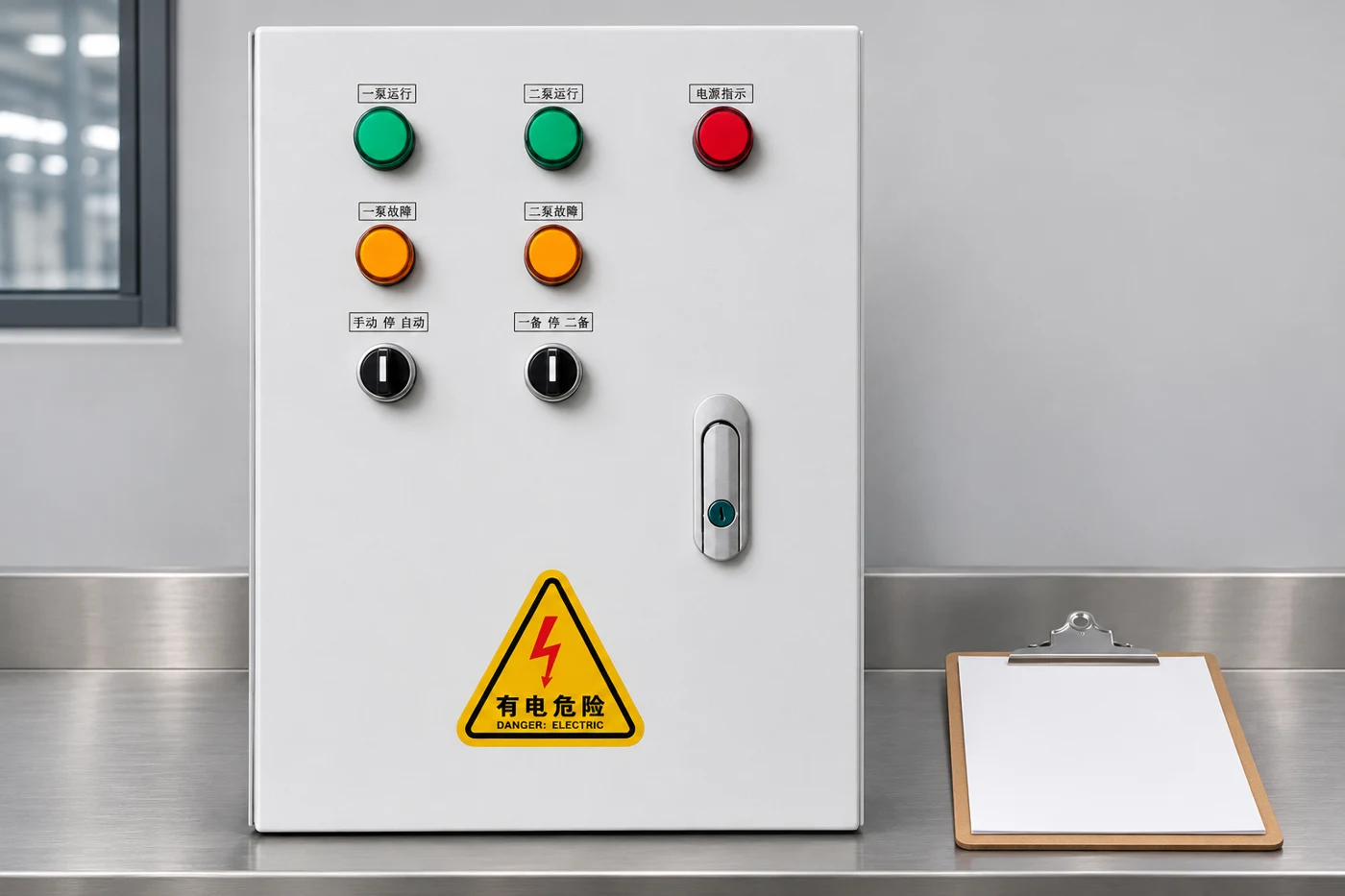
Where the panel has separate run and fault indicators, confirm what those indicators actually represent. A lamp wired from a command circuit is different from independent feedback. The as-built drawings and control description should explain that distinction. Avoid describing a lamp as proof of flow unless the design provides that measurement.
This table is a way to organize the investigation. The responsible technician must use the correct drawings, site procedures and equipment instructions to choose any physical tests. It intentionally avoids generic terminal numbers, jumper instructions and assumed float contact states.
| Observed pattern | Possible area to review | Useful record |
|---|---|---|
| High level with no pump command | Mode selection, control inputs, permissives or control power | Approved sequence, input states and event time |
| Command present but pump not running | Power, starter, protective trip or motor circuit | Command versus feedback and exact fault indication |
| Pump running but level still rises | Inflow, discharge restriction, pump condition or hydraulic duty | Level trend and available flow or pressure evidence |
| Alarm indicated with normal confirmed level | Sensor movement, contamination, wiring or configuration | Independent level observation and sensor identification |
| Local alarm works but remote alarm is absent | Output contact, communications, routing or destination | Local and remote timestamps plus notification receipt |
| Alarm returns after acknowledgement | Persistent process condition or specified latching behavior | Level condition, acknowledgement and reset sequence |
Several rows may apply to the same event. For example, a genuine high level and a failed remote notification are two separate problems. Repairing the sensor does not verify the communications path, and restoring the communications path does not establish that pumping performance is adequate.
Identify the actual alarm device: a dedicated float, a transmitter-derived signal or another approved arrangement. Record its tag, location, support and relationship to the operating level devices. Confirm whether the alarm is independent of normal starting control or shares equipment that could fail in common.
A float’s ability to move can be affected by its surroundings. The inspection should consider access, interference and accumulated material using the site’s safe method. A transmitter-based alarm needs a review of the configured range, units and alarm logic. These are different inspection tasks even when both ultimately operate the same lamp.
Do not prescribe one universal alarm elevation or separation from the pump start level. The setting must account for the system’s usable storage, inflow, response arrangements and approved design. A location suitable for one wastewater installation may be inappropriate for a clean-water filling tank or a different pump duty.
Acknowledgement records that an operator has recognized an event. Silence may stop an audible signal. Reset changes a latched state only when the design allows it. These actions are not interchangeable, and none proves that the liquid level has returned to normal.
Ask for the expected behavior while the alarm condition persists and after it clears. Does a visual indication remain after the horn is silenced? Is a remote event retained? What happens after loss and restoration of power? Record the answers in the cause-and-effect schedule and include them in acceptance testing.
Repeatedly clearing an alarm without investigating the level condition can remove useful evidence. Maintain an event history with the action taken and the reason for return to service. Where a temporary operating arrangement is necessary, it needs the site’s authorization, monitoring and restoration process rather than an undocumented bypass.
A lamp test proves only the functions included in that test. It may not exercise the field sensor, the controller input, the remote communications or the final destination. The acceptance plan should say exactly where a test stimulus is applied and which parts of the chain it verifies.
Plan checks at several levels as appropriate: the local alarm indication, the approved field input test, the output signal and receipt by the responsible operator. Record start and receipt times with the expected response. Obtain a separate restoration check so test conditions do not remain active after the work.
The final proof is operational: the intended person or monitoring service receives an intelligible alarm and knows the required action. A screen showing a transmitted event is incomplete evidence if nobody verifies the destination. Communications failures and loss of power also need behavior defined in the project design.
Electrical and wastewater hazards can exist together. Keep inspection within the site’s access, isolation and confined-space arrangements. This article does not provide instructions to enter a tank, manipulate energized terminals or defeat protective devices. A competent team must decide how to simulate inputs and observe the process safely.
The HSE electrical work guidance supports the planning and competence requirements for electrical work. It is not a substitute for the site’s equipment instructions or the procedures required for the surrounding process hazards.
For hydraulic checks, establish an approved stopping point before a controlled level rise or pump test. Do not create an overflow simply to prove an alarm. Specify who observes the process, who controls the test and how the installation returns to its normal automatic mode afterward.
A duplex system may alternate pumps normally while its high-level notification is defective. It may also alarm correctly while one pump fails to contribute useful flow. The duplex pump alternation guide covers the rotation function; the alarm review adds sensor, notification and response evidence.
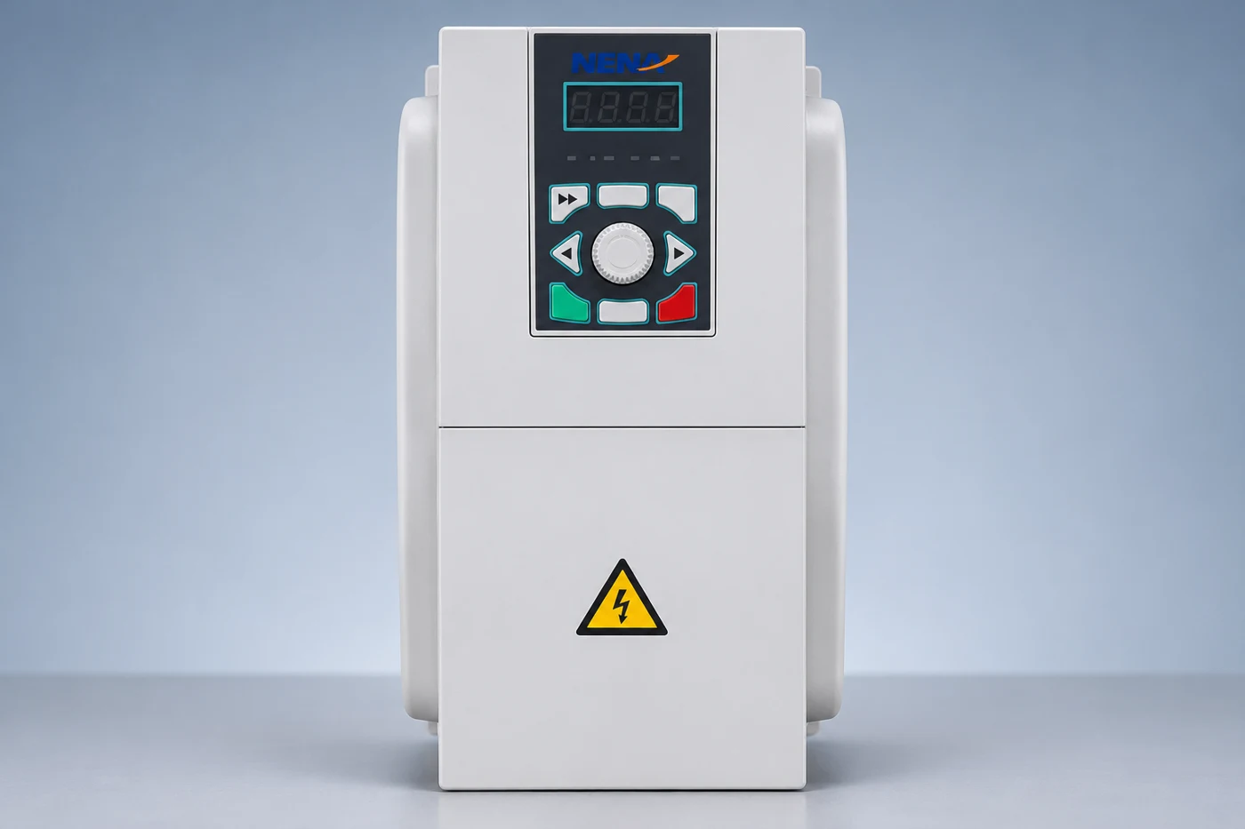
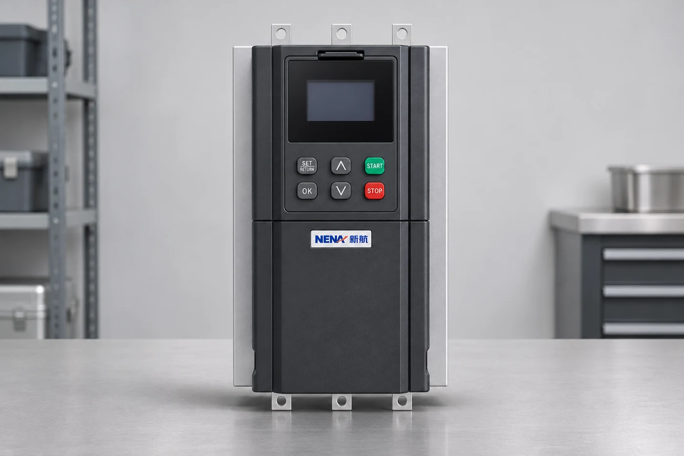
For the broader choice of equipment, begin with the motor control cabinet selection guide. Then attach a project-specific alarm schedule. A one-to-two water pump control box provides a relevant product family for discussion, but the photograph does not prove a fitted high-level input, telemetry system or independent alarm supply.
Likewise, high level and dry running are different process conditions. The solar pump dry-run protection article deals with a low-water protection task. Keep the two requirements distinct when a project combines water extraction and storage control.
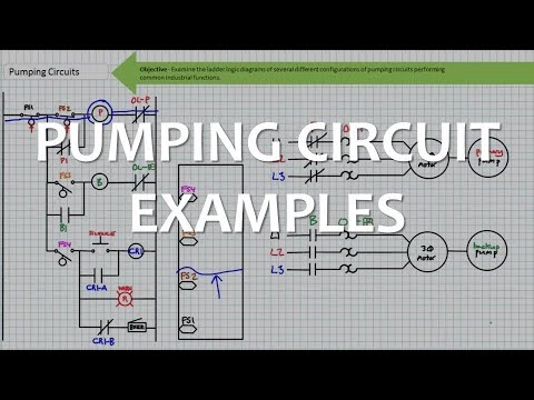
Jim Pytel’s lecture below examines several pumping and diagnostic circuits. It helps readers understand how level switches, motor control and indication can interact. The examples are educational; terminal arrangements and protective behavior must come from the approved design for the installed system.
Include the system duty, cause-and-effect schedule, level device identification, drawings, alarm destination and response contact. List the actual tests, expected outcomes, observed outcomes and restoration checks. Record limitations, including any field device or communications path that was not exercised.
Agree on maintenance checks using the equipment instructions and the site’s operating program. The interval should reflect the application and consequences of a missed alarm; a generic article cannot set it for every installation. Keep records of failed checks and corrective action so a recurring problem is visible across service visits.
A complete handover demonstrates more than a working buzzer. It shows that the defined process condition is detected, the required indications and notifications occur, an operator can respond and the installation returns to its intended operating state. That is the evidence a buyer should request before accepting an alarm function.
Not necessarily. Excess inflow, restricted discharge, an incorrect level signal or a control problem can also produce an alarm. Compare the actual level, pump command, operation and removal performance.
Only if the approved test arrangement actually includes the float circuit. A local test may check the lamp and horn without exercising the field sensor or remote notification.
No. Silence changes the audible indication according to the control design. The actual liquid level and any underlying fault still need investigation.
State the input device, required local indication, silence and reset behavior, remote destination, power-loss behavior, test method and operator response responsibilities.