A soft starter phase sequence fault means the starter’s permitted incoming phase order does not match what it detects, subject to the exact model’s protection logic. It does not by itself prove that the motor is rotating backward. Before changing a setting or moving conductors, separate three questions: what phase sequence reaches the starter, what sequence the starter is configured to accept, and what direction the driven machine actually requires. Resolve these questions through the approved drawings, equipment manual and a controlled commissioning plan.
A standard soft starter manages starting voltage; it should not be assumed to provide the electronic forward and reverse commands available on a variable frequency drive. This guide explains the evidence needed to diagnose sequence problems without turning a protection alarm into an invitation to experiment with power wiring.
Incoming phase sequence describes the order of the three supply phases. Motor rotation also depends on how those phases connect to the motor windings. The direction accepted by a pump, fan or conveyor is a mechanical requirement. A control screen reading “forward” describes a command or program state; it cannot independently verify shaft direction.
Start by writing those three facts on different lines of the commissioning sheet. Record the incoming supply identification, the motor connection drawing and the machine’s required direction with its viewing position. “Clockwise” is incomplete unless the observer’s end of the shaft is defined. Do not use cable colors alone as proof of phase identity after modifications.
The NENA soft starter overview provides the wider selection context. Sequence diagnosis is a narrower commissioning task and should not be confused with choosing a different starting method or increasing the starting current limit.
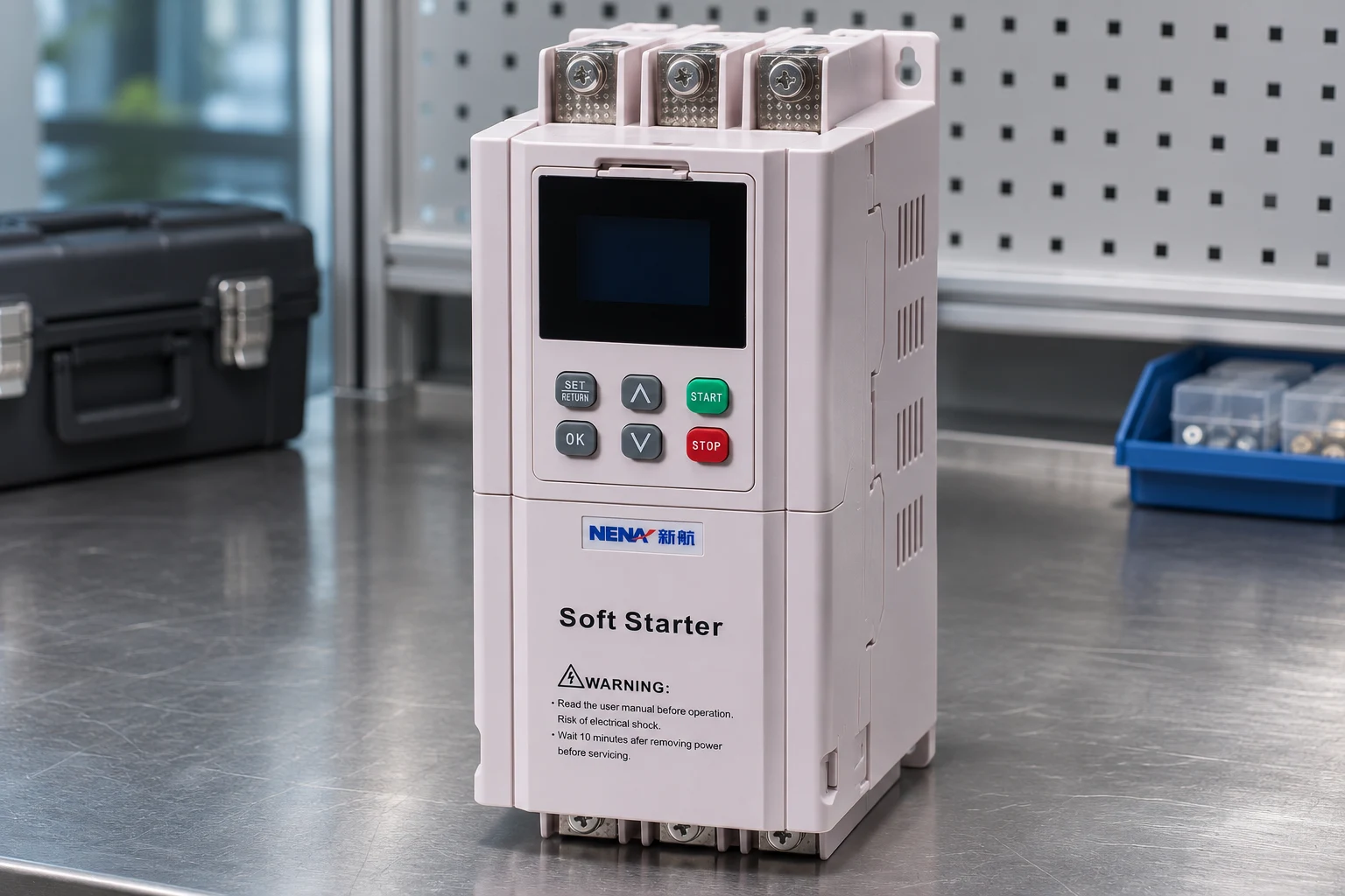
Read the exact starter model, firmware information where available and the applicable manual revision. Some equipment offers selectable phase-sequence supervision, while other designs implement different checks or parameter choices. Do not copy a parameter number, factory default or fault code from another manufacturer’s product into a NENA commissioning instruction.
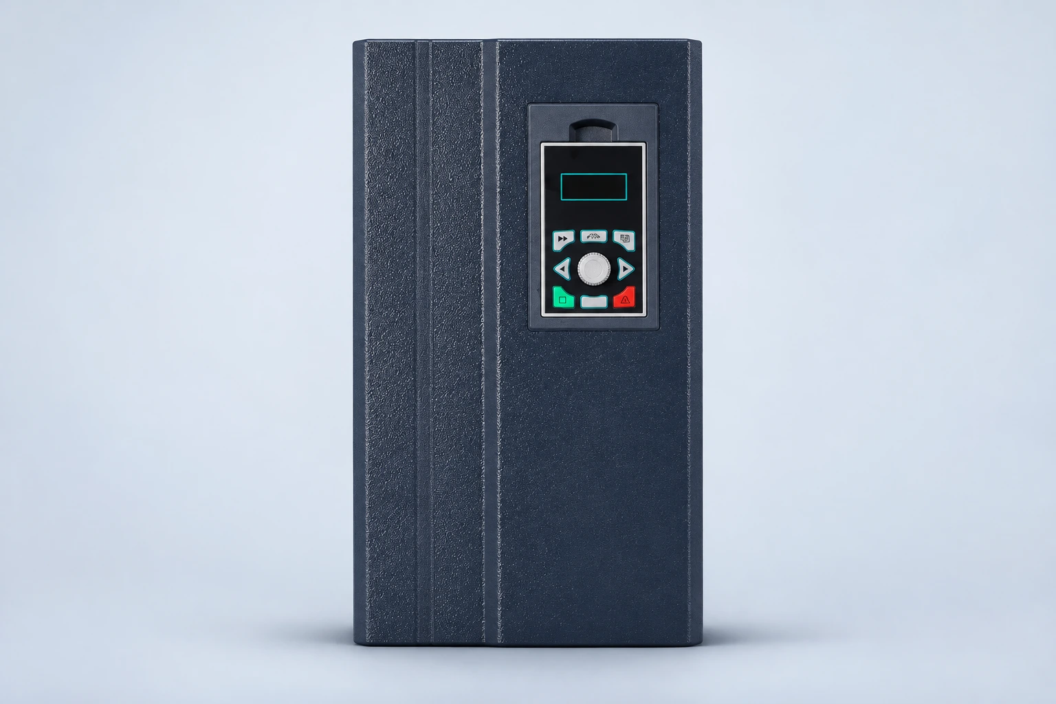
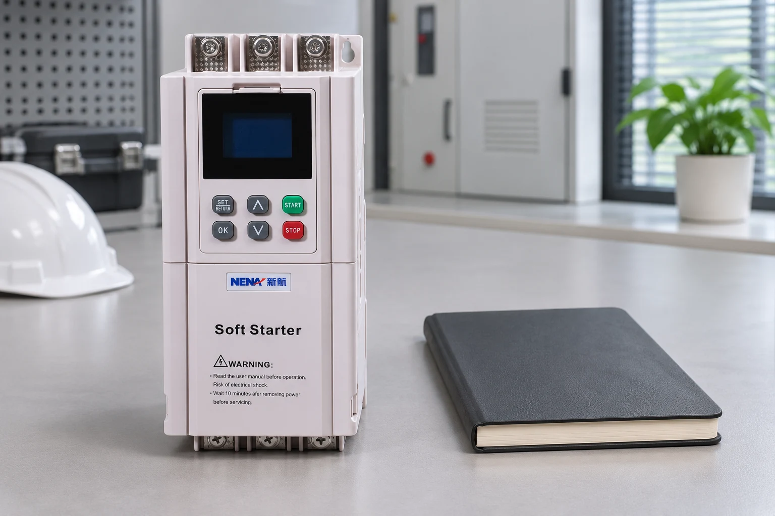
The ZR900 online soft starter product page identifies the physical product used for the illustrations. The photograph does not prove its available sequence settings or reversing capability. Ask for the supplied unit’s terminal diagram, supported connection arrangement and protection description before preparing a test method.
Preserve the current settings and fault history before any authorized change. Record whether the event appears before a start command, during acceleration or after a change in supply source. This timing helps define the investigation without assuming that every phase-related alarm has the same cause.
The following table organizes questions for a qualified commissioning team. It is not a wiring procedure. A test or modification must follow the actual starter and machine instructions, including the approved isolation and restart arrangements.
| Observed condition | Evidence needed | Question to resolve |
|---|---|---|
| Sequence alarm before starting | Exact code, supply-source identity and permitted sequence configuration | Does the detected input match the unit’s documented requirements? |
| Motor runs in the wrong direction | Approved terminal map and direction observation with viewpoint | Is the motor connection consistent with the machine requirement? |
| Problem appears after generator transfer | Sequence records for each source and transfer arrangement | Are both sources presented in the required phase order? |
| Alarm follows motor replacement | Old and new terminal records, motor nameplate and wiring diagram | Has the motor connection or starter topology changed? |
| Start fails without observed rotation | Full event log and separate voltage, protection and command checks | Is this actually a sequence issue or a different starting fault? |
A conventional soft starter does not synthesize an independently commanded output frequency and phase order in the way a VFD does. Consequently, entering a “reverse” command in a PLC does not establish that the power circuit can reverse a motor. The power architecture must support the required operating directions and transitions.
For an example of the distinction, the open educational Socratic Electronics VFD learning material examines drive concepts and associated questions. Use it as background, not as evidence of a feature on a particular soft starter. A drive and a starter need separate equipment-specific commissioning instructions.
If a project needs forward and reverse operation, request the complete reviewed power and control drawings. The design must address interlocking, stopping behavior, rotating-load conditions, protection and the manufacturer’s permitted switching arrangement. A pair of contactors mentioned in a general discussion is not a complete engineering design.
Many general motor explanations say that interchanging two phases reverses a three-phase motor. That principle does not identify the approved modification point in every starter installation. Connection topology, bypass arrangement, protection supervision and the manufacturer’s requirements matter. Inside-delta and other special arrangements cannot be treated as ordinary three-wire motor connections.
Record the proposed change against the actual drawing and ask the responsible engineer to confirm it. Identify the consequences for phase labels, sequence supervision and any bypass path. After a change, update the drawing rather than leaving the next technician to discover that labels and physical connections disagree.
Do not change both sides of a starter through trial and error. Do not bypass supervision merely to remove an alarm. A configuration change may make the alarm disappear while leaving the machine direction or the intended protection unresolved.
A motor that ran correctly yesterday may encounter a sequence problem after electrical maintenance, a temporary supply connection or a source transfer. Ask what changed before the first recorded event. Build a short chronology including the last successful start, the maintenance activity and the next start attempt.
Where multiple sources exist, identify the accepted operating combinations. A normal utility source, standby generator and temporary maintenance source should not be assumed interchangeable simply because their nominal voltages match. Sequence verification must be incorporated into the relevant source commissioning and transfer procedures.
Retain source-specific evidence. A single undated note saying “rotation checked” cannot show which source was present or where the observation was made. Record the source, circuit location, instrument identity where applicable and the person responsible for the approved check.
Phase sequence and phase loss describe different conditions. The presence of a sequence alarm does not excuse ignoring a separate missing-phase, undervoltage or connection problem. Likewise, a motor that fails to accelerate is not automatically evidence of incorrect sequence.
Use the soft starter phase loss fault guide when the event record points to missing-phase behavior. Use the soft starter troubleshooting framework to organize wider causes. Keep each conclusion tied to evidence rather than changing several protection settings at once.
Capture the original event information before clearing alarms. If the equipment supplies a timestamped log, retain it with the commissioning record. A reset that removes the only evidence can lengthen the outage and obscure whether an intermittent source issue was present.
Direction checks belong to qualified personnel with authorization for the installation and machine. A brief energization is not automatically safe: some pumps, compressors and other driven equipment can be harmed by an unsuitable test. Obtain the machine manufacturer’s requirements, permitted operating condition and observation method before planning a start.
Define who controls the start command, who observes the result and how the equipment will be stopped. Keep unauthorized personnel clear of rotating parts. Include the safeguards against unexpected automatic restart and the conditions requiring the test to be abandoned.
HSE’s electrical safe-working guidance supports work planning and isolation decisions. The local rules and the equipment owner’s approved procedures remain controlling. A stopped motor or an inactive starter display does not prove an electrically safe maintenance condition.
Close the investigation with a record showing the accepted supply sequence, starter settings, motor terminal arrangement and required direction. Attach the current drawing revision and the approved test outcome. State which supply sources and operating modes were actually checked; do not imply coverage of untested combinations.
Retain a before-and-after settings comparison if a parameter changed. Identify the authorization and the technical reason. Where no change was needed, record that conclusion too, so a later team does not repeat the same adjustment simply because the original alarm remains in a historical log.
A useful handover also identifies the next trigger for revalidation: motor replacement, power-cable work, source modification or starter replacement. This is more useful than an unsupported assurance that direction can never change again.
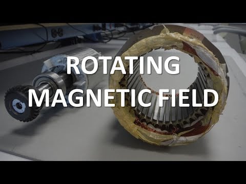
Jim Pytel’s educational lecture explains the rotating magnetic field used by three-phase machines. It helps connect supply phase order with motor behavior. The lecture is background learning; it does not identify a permitted rewiring point or protection setting for the supplied starter.
No. It concerns the starter’s detected and accepted sequence. Actual motor direction also depends on the motor connection and must be checked through the approved machine procedure.
Do not treat that as a general remedy. Confirm the cause and the protection’s intended function with the applicable manual and responsible engineer before authorizing a change.
No universal location can be prescribed. The permitted modification depends on the model, connection topology, bypass circuit and manufacturer’s instructions.
Provide the exact model, fault code, event timing, source arrangement, current drawings, motor connection information and any authorized direction or sequence test records.