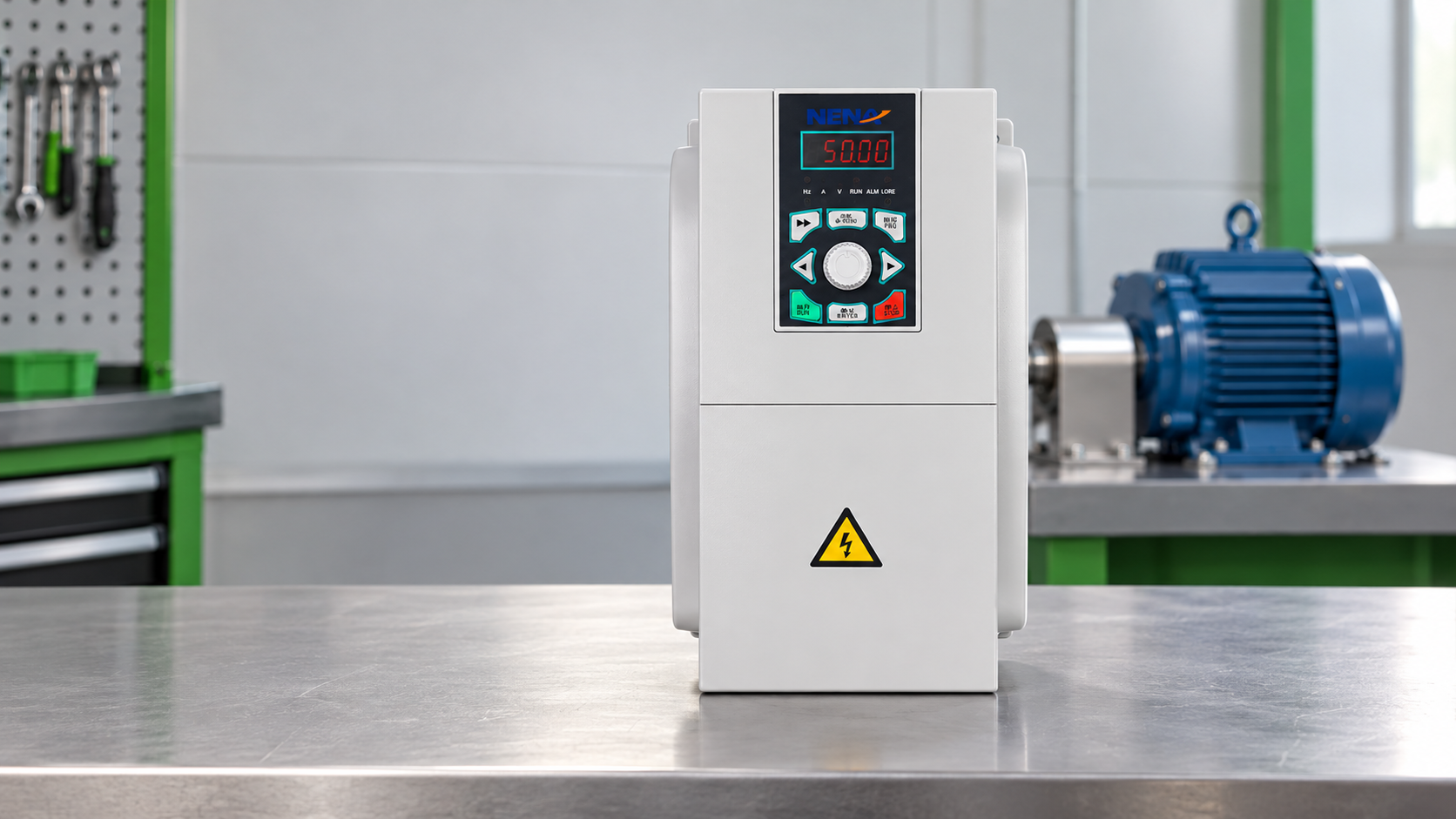
When a maintenance manager in Suzhou encountered a conveyor that tripped during acceleration, the first action was to replace the drive. The replacement still overheated after a short production run. A review found the real problem: the selected rating matched the motor’s kW, but not its overload duty, current, enclosure conditions, or stopping cycle. Once those specifications were corrected, the conveyor accelerated smoothly and the trips stopped.
Summary: A VFD motor controller converts fixed-frequency AC into controlled voltage and frequency so an induction or synchronous motor can start, run, slow, and stop at the required speed. A practical selection may compare 5.5, 7.5, and 11 kW ratings on a three-phase 380 V supply, but the motor nameplate current and duty remain decisive. Confirm the load profile, environment, braking, and protection requirements before ordering.
A VFD first rectifies incoming AC to a DC link, then uses switching devices to synthesize an output waveform with a commanded frequency and voltage. The motor’s rotating magnetic field follows that frequency. For a four-pole motor, synchronous speed is approximately 1,500 rpm at 50 Hz and 750 rpm at 25 Hz; actual shaft speed is slightly lower because of slip.
The controller also manages acceleration ramps, deceleration ramps, current limits, and—on vector-controlled models—torque response. This is why a VFD motor controller is more than an electronic on/off switch: it matches electrical output to a changing mechanical requirement. IEC 61800-2 provides a useful vocabulary for adjustable-speed drive systems, while the motor’s nameplate and the supplier’s parameter guide determine the usable operating range.
For a pump or fan, reducing speed can reduce power sharply, but only when the system curve and process setpoint permit it. A 20% speed reduction is an illustrative case: under affinity-law conditions, power varies approximately with the cube of speed, so the theoretical ratio is 0.8³, or about 51% of the original power. Field results depend on static head, control valves, leakage, motor efficiency, and runtime; the U.S. Department of Energy treats the motor and driven equipment as a system.
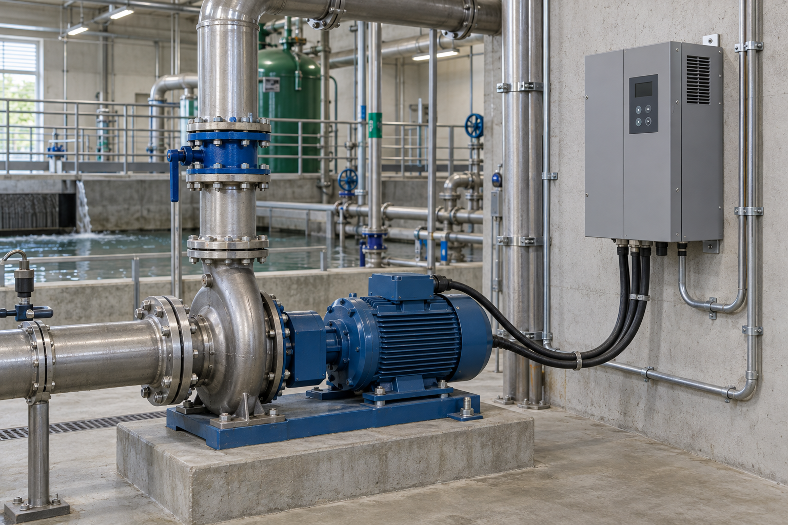
An AC drive can reduce energy use when a motor normally runs faster than the process requires, especially on centrifugal pumps and fans. The drive lowers frequency to meet a pressure, flow, or temperature setpoint instead of forcing a fixed-speed motor to run continuously against a throttling device. The DOE motor-systems guidance recommends looking at the complete operating profile rather than assuming savings from the drive alone.
Energy is only one part of total cost. Input harmonics, added heat, bypass operation, standby time, commissioning labor, filters, braking hardware, and maintenance access can change the business case. A short illustrative calculation should state its assumptions: if a 30 kW fan operates 4,000 hours per year and the control profile supports a sustained 20% speed reduction, the affinity-law estimate is not a guaranteed 30 kW × 4,000-hour saving. Measure the actual load points and tariff before approving a payback claim.
For constant-torque conveyors, mixers, and compressors, the benefit may be process control, reduced mechanical shock, or stable throughput rather than a cubic energy reduction. The correct question is not “Will every motor save energy?” but “Which operating points can be moved closer to the process requirement?”
Size a variable speed drive from motor current and duty first, then verify voltage, power, speed range, overload, ambient temperature, altitude, enclosure, cable length, braking, and control method. A drive marketed as 11 kW is not automatically suitable for every 11 kW motor: two motors can have different rated currents, starting demands, insulation systems, or overload requirements.
Use a simple procurement record:
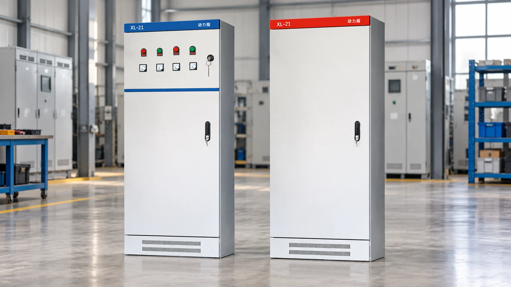
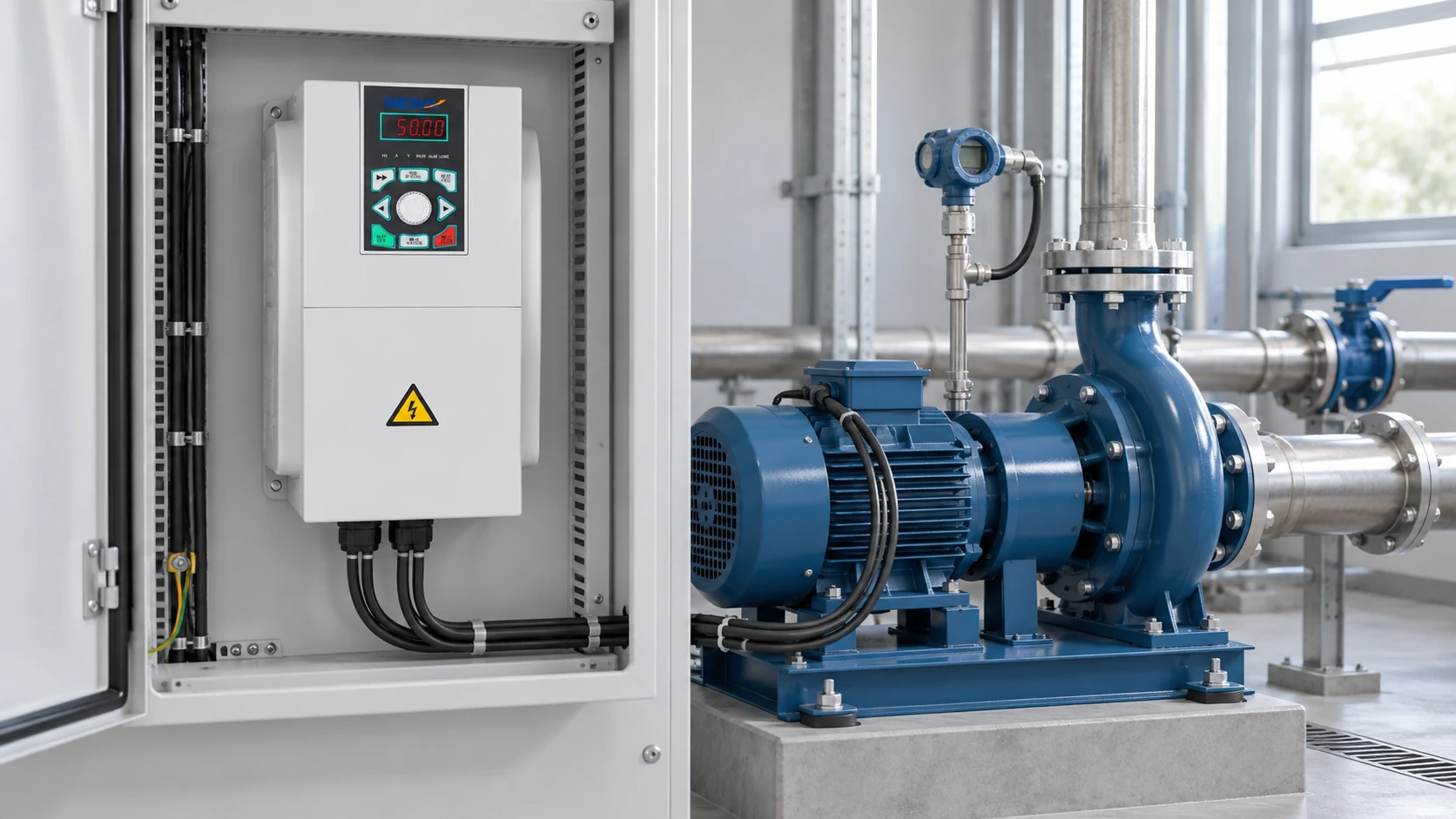
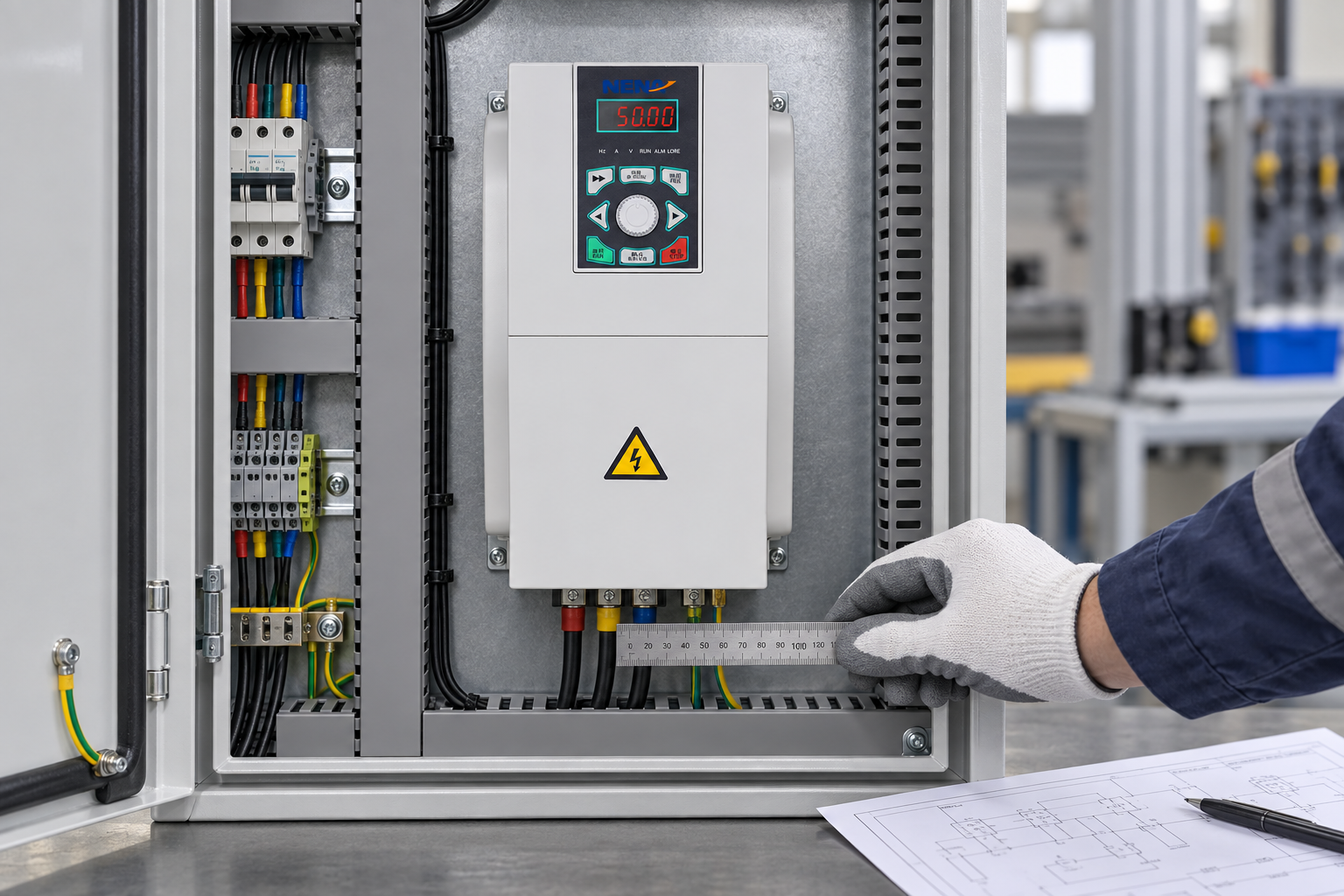
IEC 61800-5-1 is relevant to electrical, thermal, and energy-safety considerations for adjustable-speed power drive systems; it does not remove the need for a site risk assessment. If a drive is installed in a cabinet, calculate heat dissipation and leave service clearance rather than treating the enclosure as a neutral box.
The best choice depends on the load’s torque curve and consequences of interruption. A general-purpose drive may suit a pump, fan, conveyor, or basic machine; a high-performance vector drive may be justified by low-speed torque, rapid load changes, or tighter speed regulation. A soft starter reduces inrush and mechanical shock but normally does not provide continuous speed control.
| Control option | Speed control during normal running | Typical strength | Key limitation to check | TCO consideration |
|---|---|---|---|---|
| VFD / adjustable-speed drive | Continuous, programmable | Process control, ramping, and variable-speed operation | Harmonics, cooling, motor insulation, and parameters | More components and commissioning, with potential process and energy benefits |
| Soft starter | Usually fixed speed after starting | Reduced starting current and shock | Cannot regulate operating speed like a drive | Lower control complexity when speed variation is unnecessary |
| Across-the-line starter | Fixed speed | Simple starting and familiar maintenance | High inrush and abrupt acceleration | Low initial complexity; mechanical and process costs may be higher |
| Servo system | Precise closed-loop motion | Position, acceleration, and synchronization | Cost, tuning, feedback, and application complexity | Appropriate for motion-critical axes, not every pump or fan |
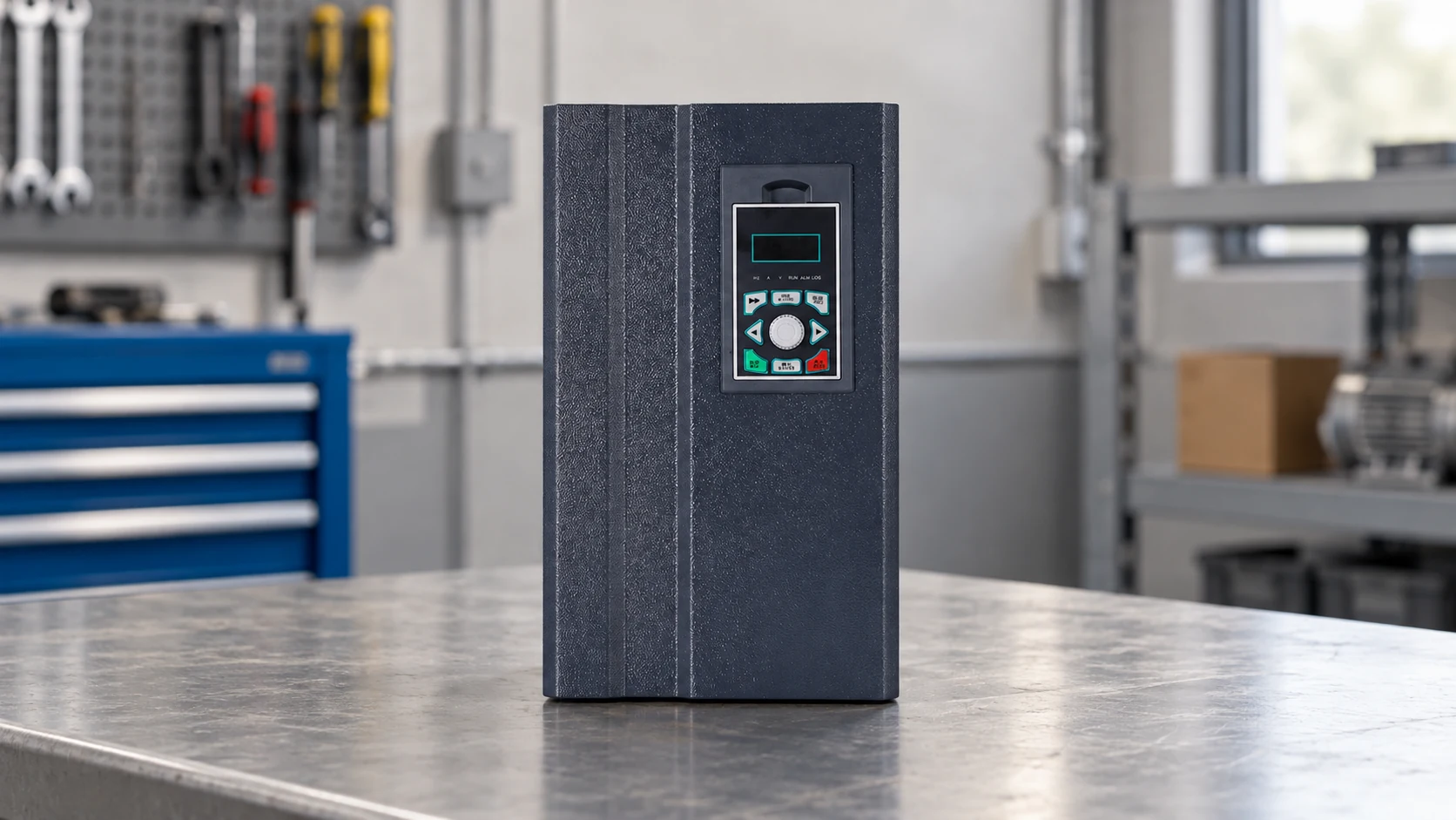
For a dimension-by-application view, public NH820 general-purpose vector inverter information lists 5.5, 7.5, and 11 kW ratings with three-phase 380 V input and applications such as industrial water pumps, boiler induced-draft fans, wire drawing, textile equipment, medium CNC, and plastic blow molding. The NH820 5.5–11 kW general-purpose inverter range is a product-range reference, not a universal compatibility statement.
| Application dimension | What the controller must handle | Practical verification |
|---|---|---|
| Water pumps and fans | Variable-torque operation, pressure or flow control, dry-run and restart logic | Compare system curve, minimum flow, static head, and bypass behavior |
| Conveyors and mixers | Starting torque, overload, frequent starts, and possible jam events | Confirm overload class, acceleration time, brake needs, and jam response |
| Wire drawing and textile equipment | Stable speed, tension changes, and coordinated control | Check feedback, low-speed cooling, synchronization, and line stopping |
| CNC and plastic blow molding | Rapid changes, repeatability, and machine interlocks | Define response time, braking energy, feedback, and machine safety circuit |
Standards references should be matched to the product, installation, and destination market. IEC 61800 is a family rather than a single blanket approval: IEC 61800-3 addresses EMC for adjustable-speed power drive systems, and IEC 61800-5-1 addresses safety requirements. A reference to an IEC standard is not, by itself, proof that a particular product is certified or that an entire installation complies.
The installer should also consider protective bonding, fault protection, cable routing, motor compatibility, residual-current protection, and safe isolation. OSHA’s control-of-hazardous-energy guidance is a useful reference for lockout/tagout practices in covered workplaces; local law and the site’s electrical rules control the actual obligation. Document who may commission, maintain, and bypass the drive, and verify that an emergency stop removes hazardous motion through the intended safety circuit.
Start with the motor and process data, not the product label. Then compare the following before asking for a quotation:
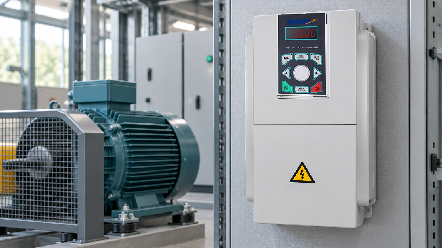
Buyers can review frequency converter and inverter options against their motor data. NENA/Zhejiang Xinhang Electrical presents frequency converters, inverters, soft starters, control cabinets, and distribution products; the final choice should still be confirmed against the application and documentation.
In ordinary industrial usage, yes: VFD means variable-frequency drive, and “variable speed drive” is a broader term often used for the same adjustable-speed equipment. The terminology can vary by supplier, and a variable speed drive may also refer to other drive technologies. Confirm the input, output, control method, and motor compatibility rather than relying on the label alone.
“AC drive VFD” usually describes an AC motor drive that varies output frequency and voltage to control speed and torque. It is a common naming combination, not a separate operating principle. Check whether the proposed unit supports the motor type, overload class, feedback, braking, and local electrical requirements.
Yes, a VFD is a motor controller for many AC induction and synchronous motor applications. It controls electrical conditions and can provide starts, stops, ramps, speed references, limits, and fault handling. It is not a complete machine-safety system by itself; guarding, isolation, interlocks, and the site’s risk assessment remain necessary.
A VFD changes the frequency of the electrical waveform supplied to the motor and coordinates voltage so the motor can produce useful torque across the commanded range. For a four-pole motor, the ideal synchronous speed is about 1,500 rpm at 50 Hz and 750 rpm at 25 Hz, before slip. The usable range depends on cooling, load torque, control mode, motor construction, and drive settings.
The reliable lesson is simple: a drive succeeds when its electrical rating, mechanical duty, environment, and safety process agree. If you need to match a motor and application, review pumps and fans application guidance and contact Xinhang for a specification discussion before placing an order.