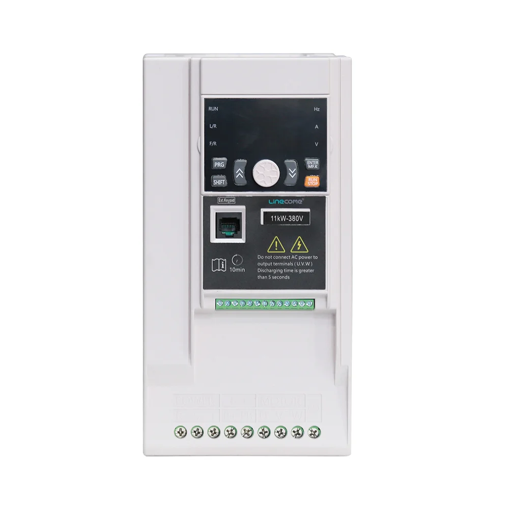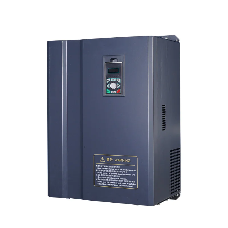
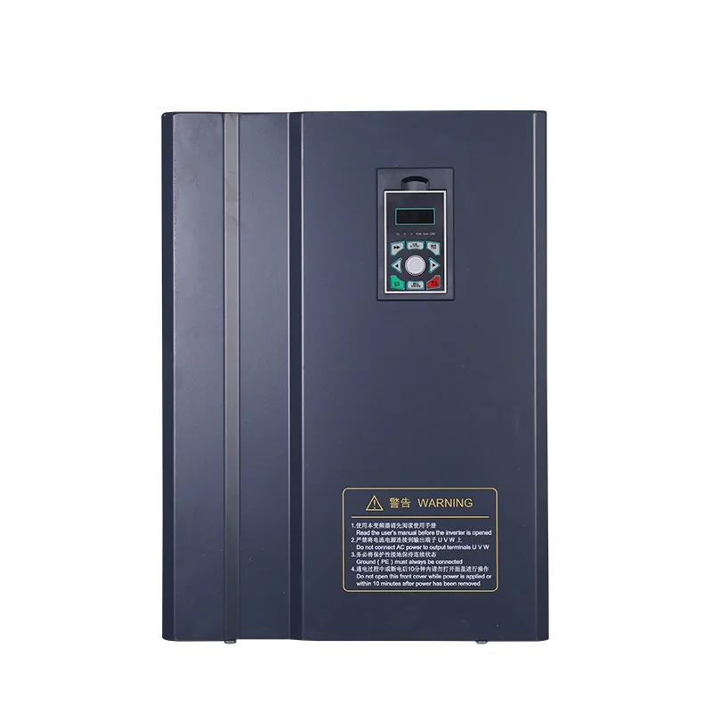
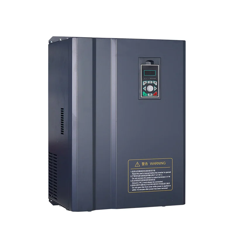
Built-in Brake Chopper PMSM VFD
Product Overview The 860ES-45-75KW Heavy Duty Permanent Magnet Synchronous VFD is an upgraded high-power heavy-load model of the NH860E series, professionally optimized for high-power permanent magnet synchronous motors. Based on the original 32-bit DSP vector control core for PMS motors, it upgrades power modules, thickened copper busbars and reinforced dual-air-channel heat dissipation…
Product Overview
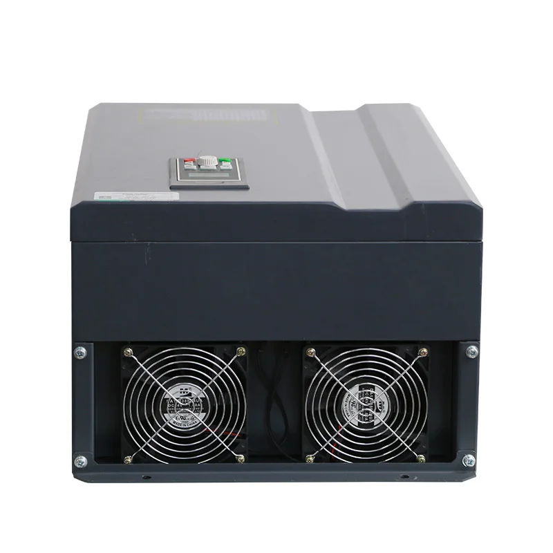
The 860ES-45-75KW Heavy Duty Permanent Magnet Synchronous VFD is an upgraded high-power heavy-load model of the NH860E series, professionally optimized for high-power permanent magnet synchronous motors. Based on the original 32-bit DSP vector control core for PMS motors, it upgrades power modules, thickened copper busbars and reinforced dual-air-channel heat dissipation structure, solving the heat dissipation and stability pain points of high-power PMS motor long-term heavy-load operation.
This heavy-duty PMS VFD retains all professional permanent magnet motor drive algorithms, enhances grid fluctuation resistance and heavy-load stall prevention capability, and optimizes DC bus energy-sharing logic. It is perfectly adapted to high-power PMS motor equipment that requires frequent startup, continuous full-load operation and high-torque output in harsh industrial environments.
Application Scenarios
Heavy-load permanent magnet synchronous motor drive for large screw air compressors, overhead cranes, mine belt conveyors, large textile printing and dyeing machinery, extrusion equipment and industrial fan & water pump units.
Product Features
Full functions of standard Permanent Magnet Synchronous VFD + exclusive heavy-load upgrades:
-
Heavy-duty PMS motor dedicated drive algorithm, more accurate torque and speed regulation for high-power permanent magnet synchronous motors
-
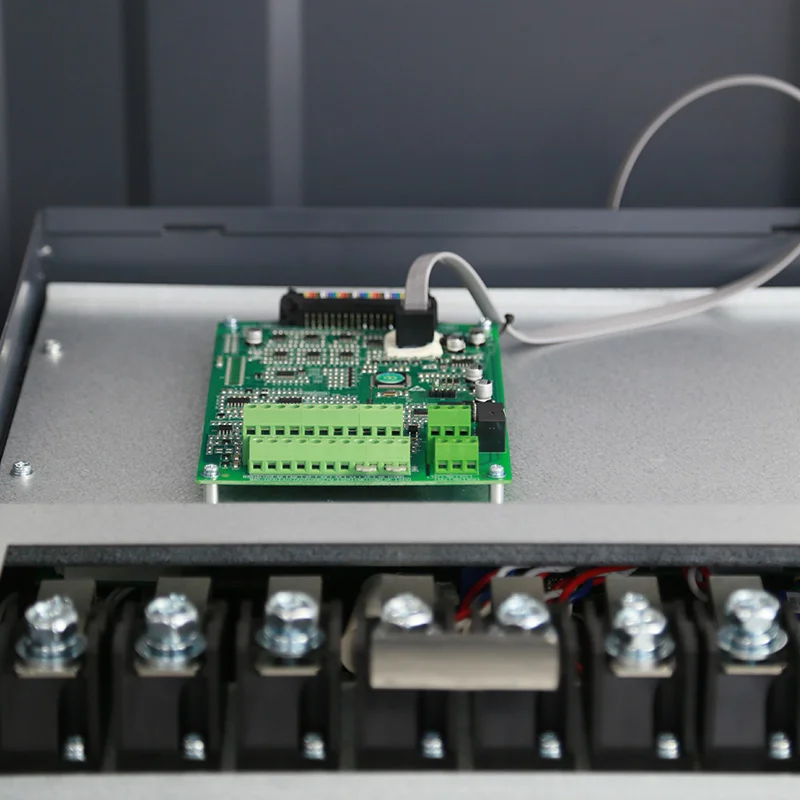
Upgraded high-current power module and thickened copper busbar, stable long-term full-load heavy-load operation
-
Dual independent air duct heat dissipation with dual cooling fans, high temperature resistance for harsh factory environments
-
Enhanced AVR wide voltage regulation, adapting to unstable power grids in mines and chemical plants
-
Reinforced over-current/over-voltage stall protection, no tripping during heavy-load startup of PMS motors
-
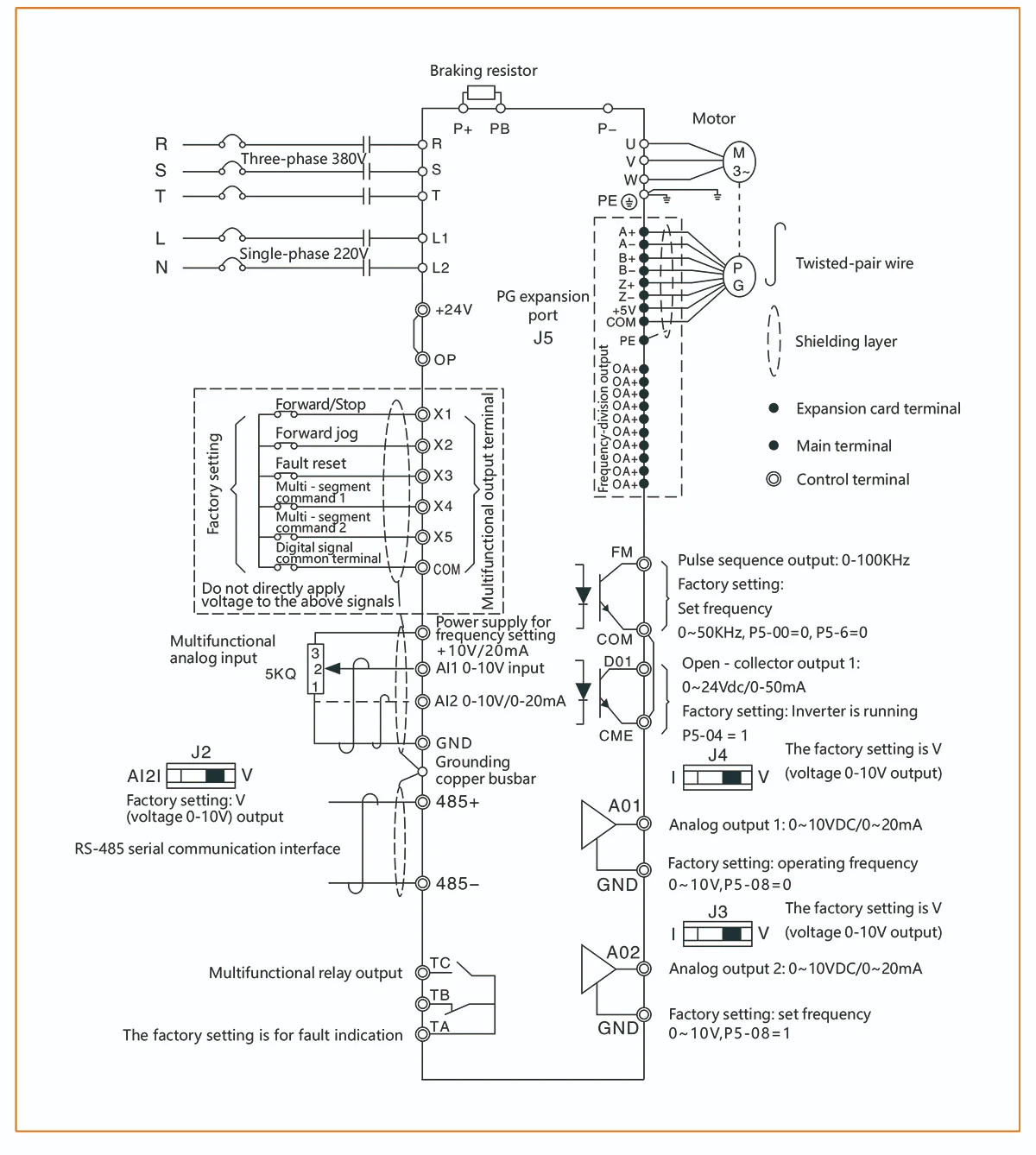
Larger braking expansion interface, suitable for frequent lifting and reversing heavy-load PMS motor equipment
-
Optimized DC bus sharing function, realizing multi-machine energy recovery and reducing industrial power consumption
-
Compatible with all encoders and expansion cards, supporting industrial Profibus-DP and MODBUS communication
| Item | Specification | |
| Control characteristics | Output frequency | 0 – 500HZ |
| Carrier frequency | 0.8kHz ~ 12kHz. The carrier frequency can be automatically adjusted according to the load characteristics. | |
| Output frequency resolution | Digital setting: 0.01Hz | |
| Analog setting: Maximum frequency × 0.025% | ||
| Control mode | Open – loop vector control (SVC) V/F control Closed – loop vector control (FVC) |
|
| Torque characteristics | With torque compensation and slip compensation, the starting torque can reach 150% at 0.25Hz (SVC) | |
| Torque control accuracy | SVC: Above 5Hz ± 5% FVC: ± 3% | |
| Over-voltage and over-current stall prevention protection | Automatically limit the voltage and current during use to prevent frequent over – voltage and over – current tripping | |
| Speed regulation range | 1:200 (SVC) 1:1000 (FVC) | |
| Speed stabilization accuracy | ±0.5% (SVC) ±0.02% (FVC) | |
| Overload capacity | 150% of the rated output current for one minute | |
| V/F curve | Four modes: linear; multi – point; complete V/f separation; incomplete V/f separation | |
| Acceleration and deceleration curve | Linear or S – curve acceleration and deceleration modes; four acceleration and deceleration times; acceleration and deceleration time range 0.1 ~ 6500.0s |
|
| DC braking | DC braking frequency: 0.00Hz ~ maximum frequency. Braking time: 0.0s ~ 36.0s, braking action current value: 0.0% ~ 100.0% | |
| Jog control | Jog frequency range: 0.00Hz ~ maximum frequency; jog acceleration and deceleration time 0.1s ~ 6500.0s | |
| Simple PLC, multi-step speed operation | Up to 16 – step speed operation can be achieved through the built – in PLC or control terminals | |
| Built – in PID | It can easily realize the process – control closed – loop control system | |
| Automatic voltage regulation (AVR) | When the grid voltage changes, it can automatically maintain a constant output voltage | |
| Fast current – limiting function | Minimize over – current faults to the greatest extent and protect the normal operation of the frequency converter | |
| Operating characteristics | Operating command channel | Three channels: given by the operation panel, given by the control terminals, given by the serial communication port. It can be switched in various ways |
| Frequency source | Ten frequency sources: given by panel knob, given by operation panel, given by analog voltage, given by analog current, given by RS485 communication, multi – speed, PID, simple PLC, which can be switched in various ways | |
| Auxiliary frequency source | Ten auxiliary frequency sources. It can flexibly achieve auxiliary frequency fine – tuning and frequency synthesis | |
| Input terminals | Five digital input terminals, one of which can be used as a high – speed pulse input. Two analog input channels, AI1: input range 0 ~ +10V, AI2: input range 0 ~ +10V/0 – 20mA |
|
| Output terminals | One high – speed pulse output terminal, capable of outputting a square – wave signal from 0kHz ~ 50kHz, which can realize the output of physical quantities such as set frequency and output frequency. It can be selected as open – drain type One digital output terminal One relay output terminal Two analog output terminals: 0V ~ 10V/0 – 20mA, which can indicate the output of output frequency/current/voltage/frequency command/rotational speed/power factor signals |
|
| Display and keyboard operation | LED display | It is equipped with 8 function keys, a 5 – digit 7 – segment LED, and 5 status LED indicators It can perform forward rotation, reverse rotation, reset, stop, jog, as well as parameter setting and display |
| Protectioncharacteristics | Protection function | Motor short – circuit detection upon power – on, input and output phase – loss protection, over – current protection, over – voltage protection, under – voltage protection, over – heat protection, overload protection, short – circuit protection, etc |
| Othercharacteristics | Optional card | IO expansion card, communication card (isolated type), PG card |
| Multi – encoder support | Supports differential, open – drain, UVW, resolver | |
| Environment | Application place | Indoors, not directly exposed to sunlight, free from dust, corrosive gases, flammable gases, oil mist, water vapor, dripping water or salt, etc |
| Altitude | Less than 1000m | |
| Ambient humidity | – 10℃ ~ + 40℃ (When the ambient temperature is between 40℃ ~ 50℃, derating operation is required) | |
| Humidity | Less than 95%RH, without water droplet condensation | |
| Vibration | Less than 5.9m/s² (0.6g) | |
| Storage temperature | – 20℃ ~ + 60℃ | |
Related Products
Sensorless Control PMSM VFD
View Details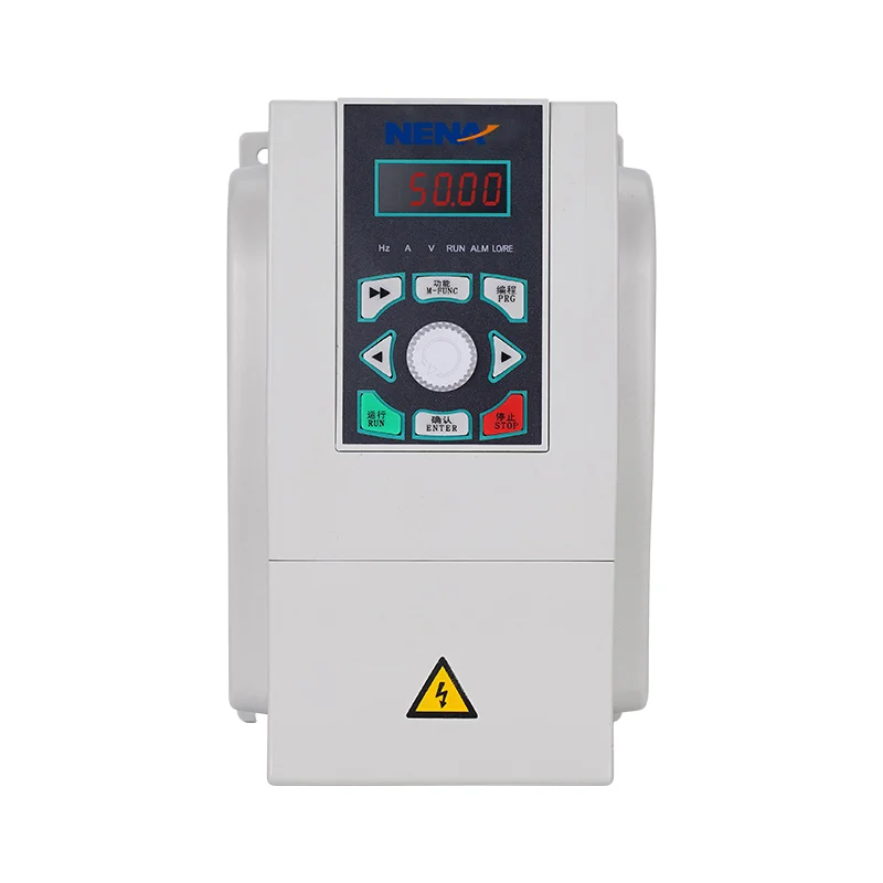
Energy Efficient General Purpose Inverter
View Details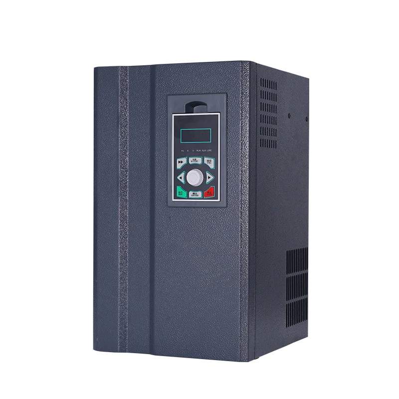
Overload Tolerant PMSM VFD
View DetailsOpen-loop Vector Inverter
View Details
MPPT Solar Water Pump Inverter
View Details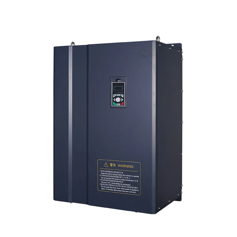
Regenerative PMSM VFD
View Details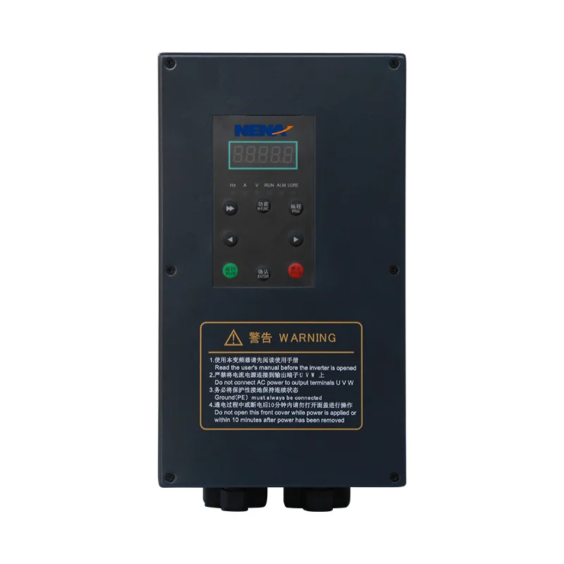
Auto-reset General-purpose Inverter
View Details
Position Control Current Vector Inverter
View Details
Single-phase Input Frequency Converter
View Details
Hybrid Input Solar Water Pump Inverter
View Details
LCD Keypad Current Vector Inverter
View Details