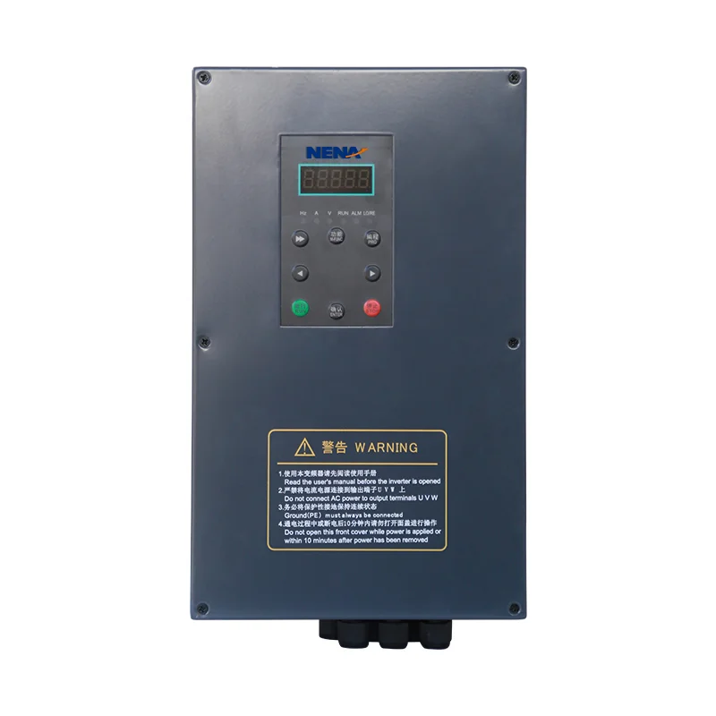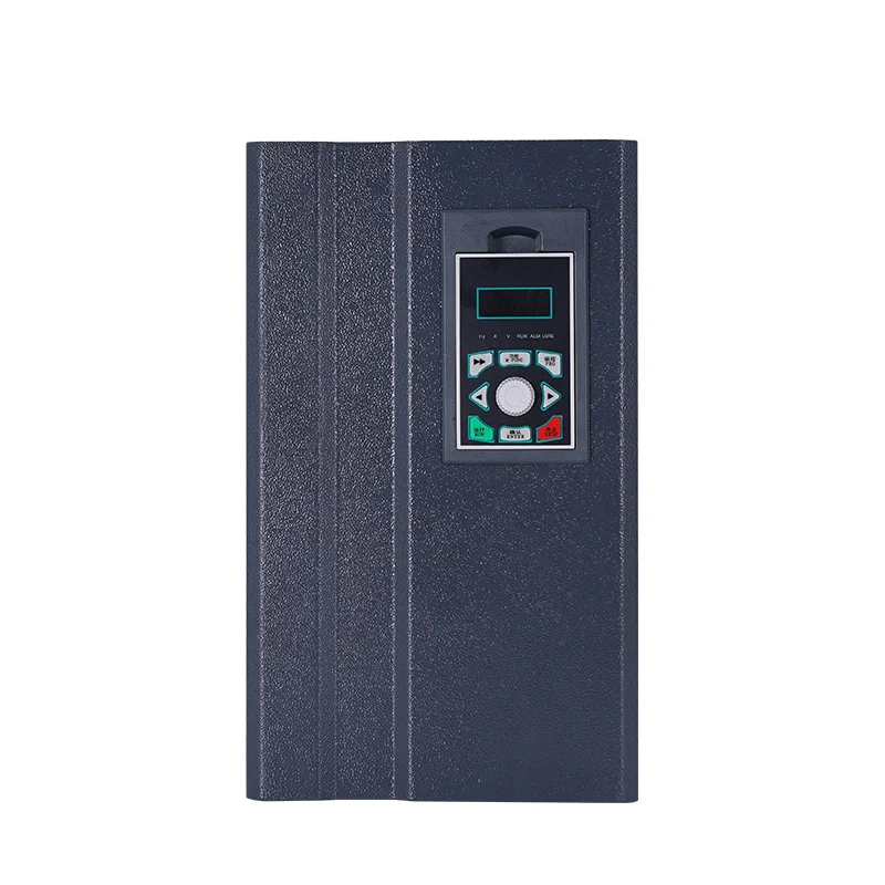
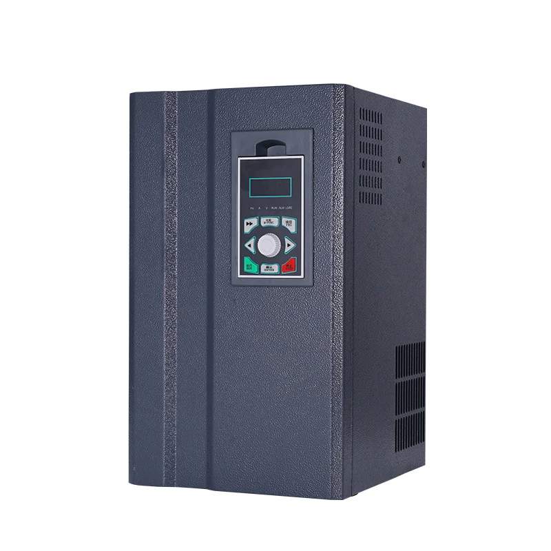
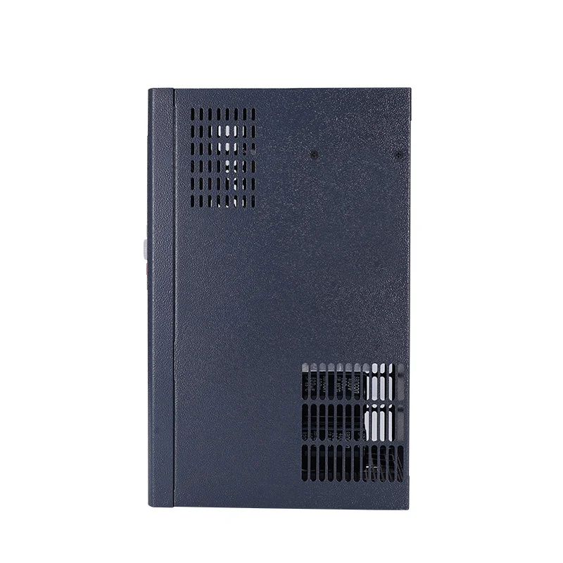
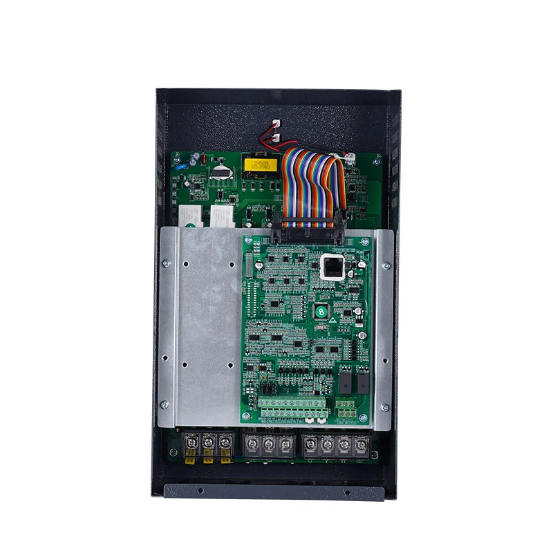
LCD Keypad Current Vector Inverter
860S series general – purpose current vector inverters feature powerful current vector control performance, enabling higher performance and higher – precision motor drive control They come with a variety of expansion card options, have powerfulfunctions, and support multiple field buses. With more abundant frequency source superposition and switching methods, advancedPID algorithms, 16…
860S series general – purpose current vector inverters feature powerful current vector control performance, enabling higher
performance and higher – precision motor drive control They come with a variety of expansion card options, have powerfulfunctions, and support multiple field buses. With more abundant frequency source superposition and switching methods, advancedPID algorithms, 16 step speed and automatic program operation, as well as frequency swing control and speed trackingunctions, while improving the product’s reliability and environmental adaptability they also strengthen customer friendliness andindustry – specific design. The functions are more optimized, applications are more flexible, and the performance is more stableThey can be widely used in industries such as CNCmachining centers, lifting equipment, printing and packaging equipment,textileequipment, dyeing and printing equipment, metal products, petrochemicals, and high – end application scenarios. This series isstandard – equipped with 485 communication function, and the models with a power of 22kW and below are standard – equipped
with a braking unit. Power range: 0.75KW~5.5KW – 220V, 0.75KW~750KW – 380V.
Industry application:
Industries such as CNC machining centers,lifting equipment, printing and packagingequipment, textile equipment, dyeing andprinting equipment, metal products,petrochemicals, and high – end applicationscenarios.
Reliability:
Multiple protection functions: over – voltage, over – current,overload, over – heat, etc.Setting of over – voltage and over – current stall protection
levelsTwo – segment skip frequencies can effectively avoid mechanical resonance points
High – performance:
Automatic torque boost: Starting torque can reach 150% at 0.5Hz
Automatic slip compensation: More accurate speed
No – stop during momentary power failure: Maintain short – time operation during momentary power outage
Low noise: Smoother motor operation
Overload capacity: Can operate at 150% rated torque for 60 seconds
Multifunctiona:
Pulse input for frequency control
Main/auxiliary frequency addition and subtraction control frequency methods
Maximum pulse output up to 100KHZ
Can display voltage, current set frequency, output frequency, rotational speed, etc. according to user definition
Frequency – swing, fixed – length and counting functionsBuilt – in PLC can operate in 16 step speedPULSE pulse setting, RS485 communication setting
Supports multiple frequency settings: digital setting, analog setting, PID setting, multi – step speed setting, simple PLC setting
Embedded RS485 communication interface, supports Modbus protocol
Input and output:
Input functions: two wire/three – wire control mode, external EF, UP/DOWN,automatic program operation control counting, pulse input, etc
Output functions: counting – reached indication frequency – reached indication, over torque indication, overload early warning, etc.
The models with 0.75 – 22kW can have a built – in braking unit
| Item | Specification | |
| Control characteristics | Output frequency | 0 – 500HZ |
| Carrier frequency | 0.8kHz ~ 12kHz. The carrier frequency can be automatically adjusted according to the load characteristics. | |
| Output frequency resolution | Digital setting: 0.01Hz | |
| Analog setting: Maximum frequency × 0.025% | ||
| Control mode | Open – loop vector control (SVC) V/F control Closed – loop vector control (FVC) |
|
| Torque characteristics | With torque compensation and slip compensation, the starting torque can reach 150% at 0.25Hz (SVC) | |
| Torque control accuracy | SVC: Above 5Hz ± 5% FVC: ± 3% | |
| Over-voltage and over-current stall prevention protection | Automatically limit the voltage and current during use to prevent frequent over – voltage and over – current tripping | |
| Speed regulation range | 1:200 (SVC) 1:1000 (FVC) | |
| Speed stabilization accuracy | ±0.5% (SVC) ±0.02% (FVC) | |
| Overload capacity | 150% of the rated output current for one minute | |
| V/F curve | Four modes: linear; multi – point; complete V/f separation; incomplete V/f separation | |
| Acceleration and deceleration curve | Linear or S – curve acceleration and deceleration modes; four acceleration and deceleration times; acceleration and deceleration time range 0.1 ~ 6500.0s |
|
| DC braking | DC braking frequency: 0.00Hz ~ maximum frequency. Braking time: 0.0s ~ 36.0s, braking action current value: 0.0% ~ 100.0% | |
| Jog control | Jog frequency range: 0.00Hz ~ maximum frequency; jog acceleration and deceleration time 0.1s ~ 6500.0s | |
| Simple PLC, multi-step speed operation | Up to 16 – step speed operation can be achieved through the built – in PLC or control terminals | |
| Built – in PID | It can easily realize the process – control closed – loop control system | |
| Automatic voltage regulation (AVR) | When the grid voltage changes, it can automatically maintain a constant output voltage | |
| Fast current – limiting function | Minimize over – current faults to the greatest extent and protect the normal operation of the frequency converter | |
| Operating characteristics | Operating command channel | Three channels: given by the operation panel, given by the control terminals, given by the serial communication port. It can be switched in various ways |
| Frequency source | Ten frequency sources: given by panel knob, given by operation panel, given by analog voltage, given by analog current, given by RS485 communication, multi – speed, PID, simple PLC, which can be switched in various ways | |
| Auxiliary frequency source | Ten auxiliary frequency sources. It can flexibly achieve auxiliary frequency fine – tuning and frequency synthesis | |
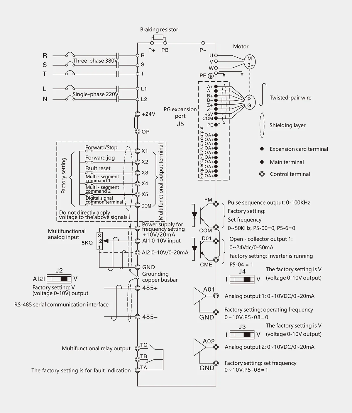
| Input terminals | Five digital input terminals, one of which can be used as a high – speed pulse input. Two analog input channels, AI1: input range 0 ~ +10V, AI2: input range 0 ~ +10V/0 – 20mA |
|
| Output terminals | One high – speed pulse output terminal, capable of outputting a square – wave signal from 0kHz ~ 50kHz, which can realize the output of physical quantities such as set frequency and output frequency. It can be selected as open – drain type One digital output terminal One relay output terminal Two analog output terminals: 0V ~ 10V/0 – 20mA, which can indicate the output of output frequency/current/voltage/frequency command/rotational speed/power factor signals |
|
| Display and keyboard operation | LED display | It is equipped with 8 function keys, a 5 – digit 7 – segment LED, and 5 status LED indicators It can perform forward rotation, reverse rotation, reset, stop, jog, as well as parameter setting and display |
| Protectioncharacteristics | Protection function | Motor short – circuit detection upon power – on, input and output phase – loss protection, over – current protection, over – voltage protection, under – voltage protection, over – heat protection, overload protection, short – circuit protection, etc |
| Othercharacteristics | Optional card | IO expansion card, communication card (isolated type), PG card |
| Multi – encoder support | Supports differential, open – drain, UVW, resolver | |
| Environment | Application place | Indoors, not directly exposed to sunlight, free from dust, corrosive gases, flammable gases, oil mist, water vapor, dripping water or salt, etc |
| Altitude | Less than 1000m | |
| Ambient humidity | – 10℃ ~ + 40℃ (When the ambient temperature is between 40℃ ~ 50℃, derating operation is required) | |
| Humidity | Less than 95%RH, without water droplet condensation | |
| Vibration | Less than 5.9m/s² (0.6g) | |
| Storage temperature | – 20℃ ~ + 60℃ |
Related Products
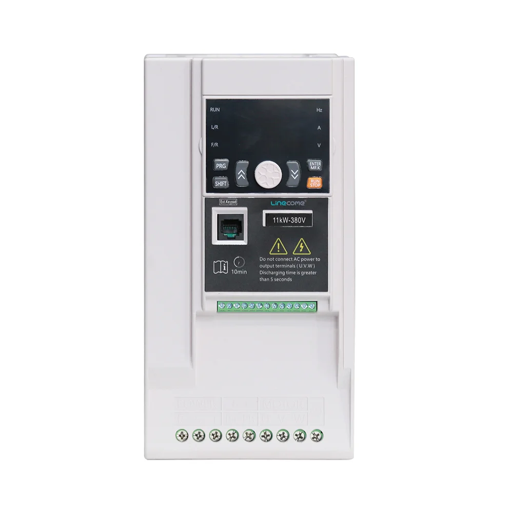
Built-in PLC Frequency Converter
View Details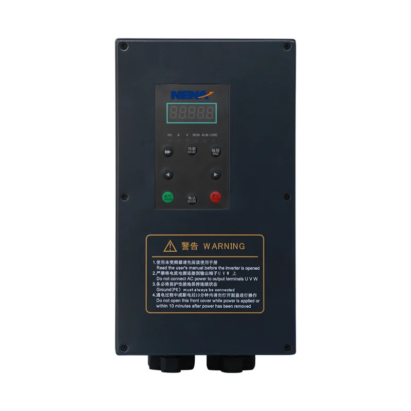
Auto-reset General-purpose Inverter
View Details
Built-in Brake Chopper PMSM VFD
View Details
AVR General-purpose Inverter
View Details
High Overload Current Vector Inverter
View Details
Vector Control General Purpose Inverter
View Details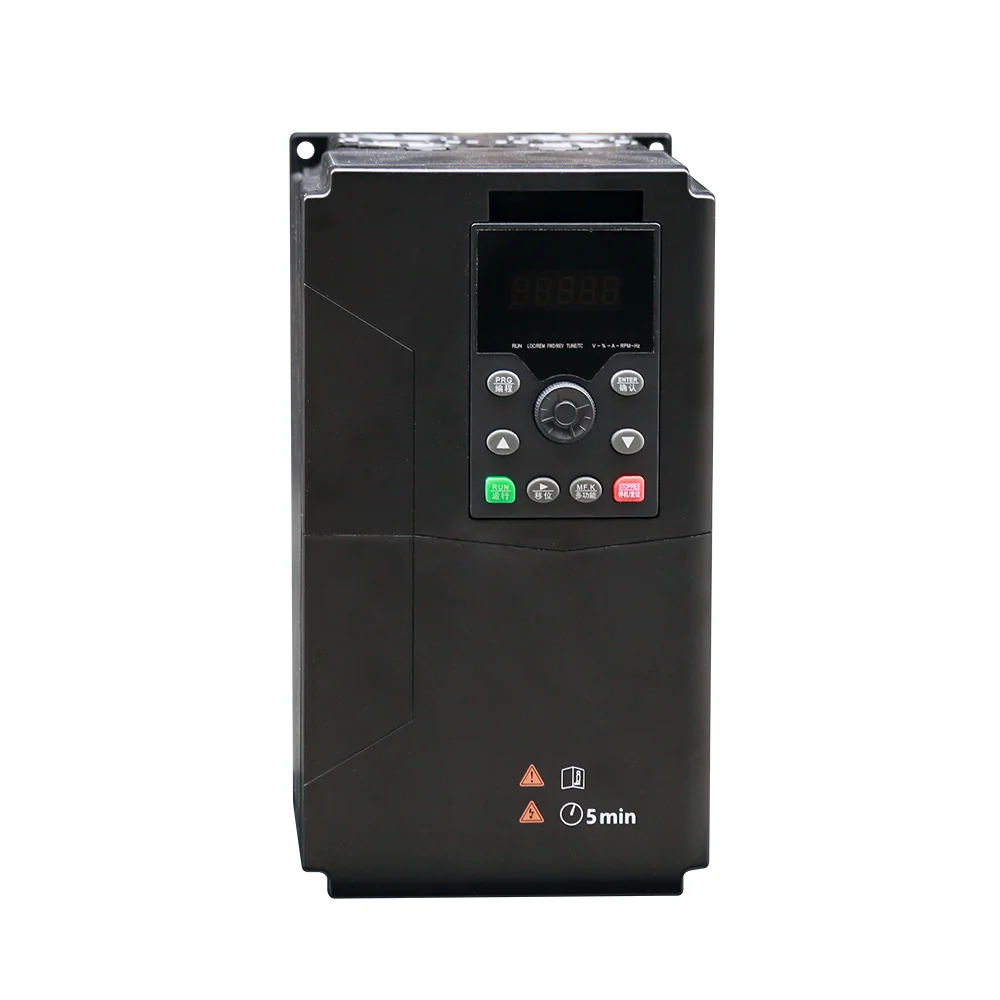
Wide PV Input Solar Water Pump Inverter
View Details
MPPT Solar Water Pump Inverter
View Details
Regenerative PMSM VFD
View Details
Real-time Clock Current Vector Inverter
View Details
Sensorless Control PMSM VFD
View Details