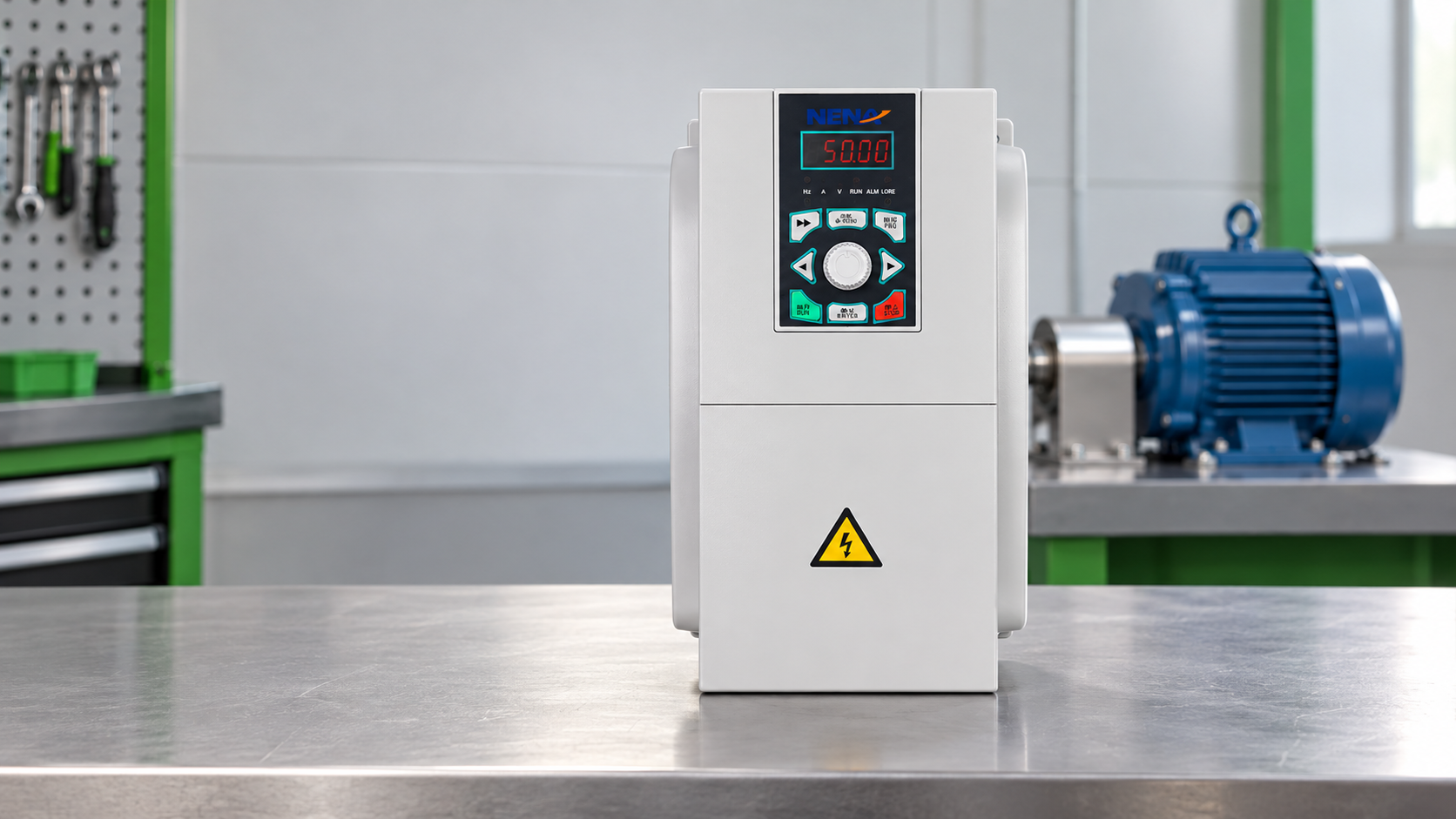
Motor starter safety checks before testing
Testing starts before a meter touches a terminal. Follow the site’s lockout/tagout procedure and use qualified electrical personnel for energized diagnostics. OSHA’s control of hazardous energy guidance and NFPA 70E are useful references for electrical work practices. They do not replace the local risk assessment, panel labeling, or manufacturer’s manual.
With the feeder isolated, look for heat marks, loose terminals, cracked insulation, dust bridges, moisture, failed door interlocks, and contactor wear. A burned contact tip, swollen overload relay, or darkened terminal block can tell more than a fault code.
| Checkpoint | What to verify | Why it matters |
|---|---|---|
| Isolation | Feeder locked out, stored energy discharged, test instrument proven | Prevents accidental energizing during inspection |
| Panel condition | Moisture, dust, heat marks, loose wiring, damaged labels | Identifies cabinet faults before component testing |
| Motor data | Voltage, full-load current, phase, duty, service factor | Sets the correct reference for current and overload checks |
| Load condition | Pump valve position, conveyor jam, fan damper, compressor unloading | Prevents blaming the starter for a mechanical stall |
How to test a motor starter control circuit
A conventional magnetic motor starter has two sides: the power path and the control path. The power path carries motor current through contactor poles and overload protection. The control path energizes the coil through start/stop buttons, auxiliary contacts, pressure switches, PLC outputs, safety relays, float switches, or other interlocks.
After isolation checks are complete and the site permits controlled testing, verify the control voltage at the starter coil terminals during a start command. A coil rated for 220 V AC will not pull in reliably at a much lower voltage. If the command is present but the contactor does not close, suspect coil failure, mechanical binding, or incorrect coil rating. If the command is absent, trace the control chain.
Next, check the seal-in circuit. Many start failures are open auxiliary contacts, loose pushbutton wiring, miswired PLC permissives, or an overload relay contact that never reset. A reset button that clicks is not proof that the normally closed overload contact is healthy. Confirm continuity through the actual terminals shown on the drawing.
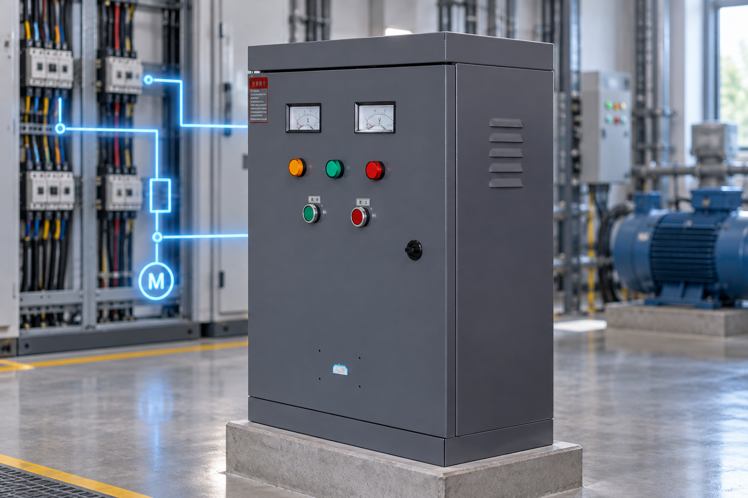
For older panels, document what is installed before ordering parts. A request to repair solenoid starter motor assemblies may really mean replacing a contactor coil, plunger, auxiliary block, or complete starter section; use the wiring diagram and nameplate instead of the phrase used in a maintenance note.
Motor starter power-path tests with a meter
With power off and the motor leads identified, measure continuity through each contactor pole while the contactor is manually operated only if the device design allows it safely. Large differences between poles suggest worn contacts, contamination, or mechanical misalignment. Do not file modern contact tips unless the manufacturer specifically permits it.
Insulation resistance testing may be needed when moisture, cable damage, or winding failure is suspected. Disconnect sensitive electronics before megger testing and follow the motor manufacturer’s voltage limits. A failed winding can make a good starter look bad because the overload trips correctly.
For energized testing, measure line voltage phase-to-phase at the starter input, then at the starter output during the start attempt. A strong input with a weak or missing output points toward the starter. A weak input points upstream. A balanced output with high current and no acceleration points toward the motor, cable, or driven load.
| Symptom | Likely area | Practical test | Typical action |
|---|---|---|---|
| Contactor does not pull in | Control circuit or coil | Measure coil voltage during start command | Repair interlock chain or replace correct-rated coil |
| Contactor pulls in, motor silent | Power path | Check output voltage across all phases | Inspect contacts, fuses, breaker, and terminals |
| Motor starts then trips overload | Load, motor, or overload setting | Compare running current with nameplate FLA | Correct load issue, motor fault, or overload setup |
| Frequent contactor chatter | Low control voltage or coil circuit | Log voltage drop during pull-in | Fix control transformer, wiring, or supply dip |
Testing overloads and protection in a motor starter
The overload relay disconnects control power when motor current or thermal model behavior becomes unsafe. Check that the overload range matches the motor full-load current and that the reset mode suits the process. Automatic reset may be unacceptable where an unexpected restart creates risk.
Thermal overloads, electronic overloads, phase-loss protection, phase-sequence relays, fuses, and motor protection circuit breakers each have a different job. IEC 60947-4-1 covers electromechanical contactors and motor-starters, while UL 60947-4-1 is relevant for North American low-voltage contactors and motor-starters. NEMA’s standards catalog is also useful when projects specify NEMA motor control conventions.
During a controlled start, clamp each phase and compare current to the motor nameplate. A current imbalance can indicate supply imbalance, contact resistance, winding problems, or cable issues. If current rises quickly and the shaft does not accelerate, stop the test and investigate the mechanical load.
Motor starter selection after a failed test
Testing often ends with a replacement decision. Do not size a new motor starter only by motor kW. Confirm rated operational current, utilization category, coil voltage, control scheme, overload range, enclosure temperature, short-circuit coordination, and starts per hour.
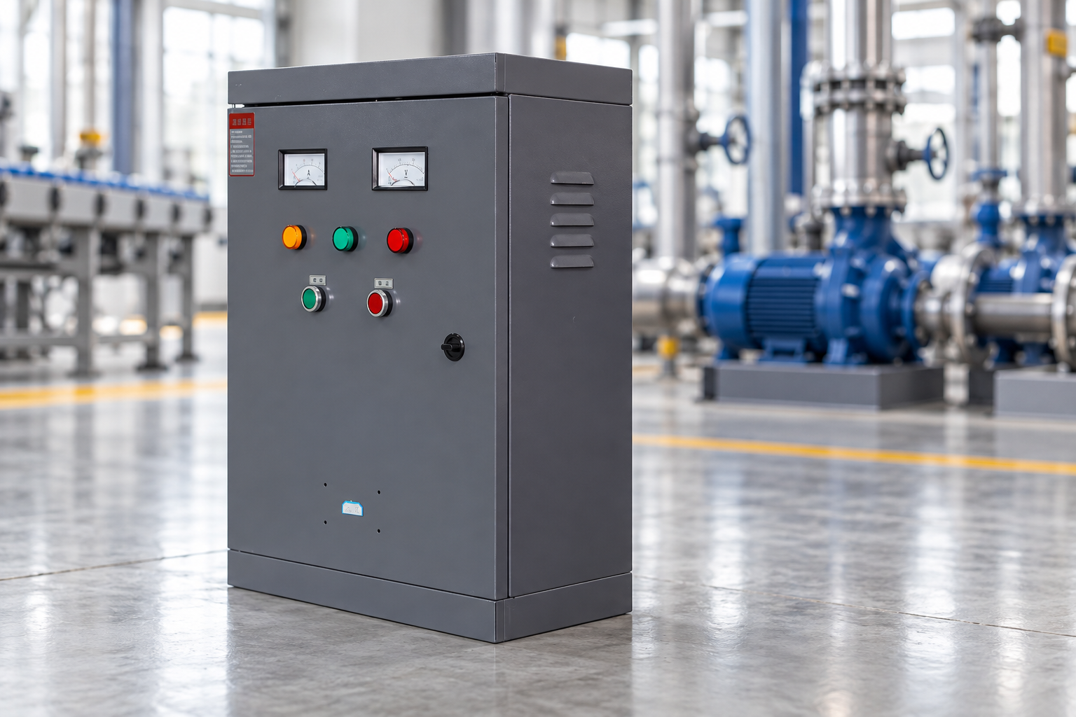
| Starter option | Best application fit | Testing clue that points here | Xinhang reference |
|---|---|---|---|
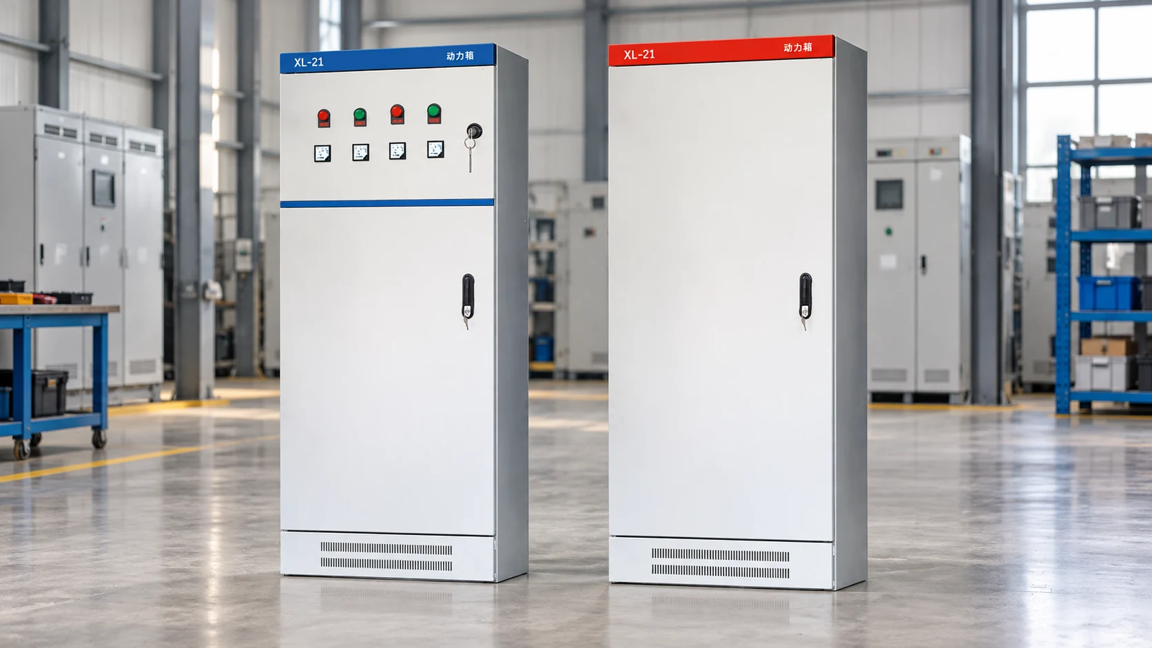
| Direct-on-line magnetic starter | Small motors with strong supply and simple loads | Starter failed mechanically, but inrush is acceptable | Custom control cabinet discussion |
| Star-delta starter cabinet | Motors with six leads and suitable low-inertia loads | Direct starting causes voltage dip, but speed control is not required | QX4 star-delta starter cabinet |
| Autotransformer reduced-voltage starter | Higher starting torque than star-delta with reduced line current | Load needs controlled reduced-voltage starting without a drive | Autotransformer reduced-voltage starter cabinet |
| Soft starter | Pumps, fans, conveyors, and fixed-speed machinery needing smooth starts | Mechanical shock or water hammer is the main failure driver | Xinhang soft starter solutions |
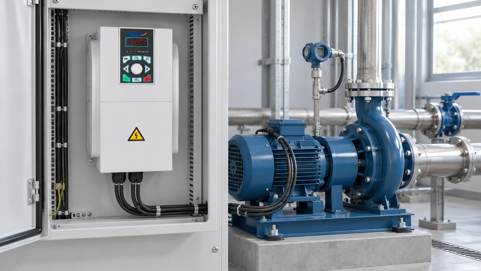
For pump stations and conveyor lines, the motor starter is only one part of the starting system. Valve timing, line pressure, material loading, restart intervals, and PLC permissives can change the correct cabinet design. Xinhang’s work with water treatment pump stations shows why starter testing should lead into application review, not just component replacement.
Motor starter test record and handover
A useful test record is short: date, equipment tag, motor nameplate data, starter model, control voltage, input voltage, output voltage, phase current, overload setting, fault indication, visual findings, and corrective action.
If repeated faults remain after contactor, overload, and motor checks, bring the cabinet drawing and load profile into the review. Xinhang can help compare replacement starter cabinets, soft starter upgrades, and application-specific control schemes. For a measured recommendation, send the motor nameplate, fault description, panel photos, and duty details through the contact page.
Frequently Asked Questions
What does a motor starter do?
A motor starter starts and stops an electric motor while providing control and protection functions. A basic starter uses a contactor and overload relay; a reduced-voltage or soft starter adds a controlled starting method to reduce current shock, torque shock, or process stress.
How do I know if my motor starter is bad?
A motor starter may be bad if the coil receives correct voltage but does not pull in, if one contact pole has high resistance, if output voltage is missing on one phase, if the overload contact will not reset, or if there is visible heat damage. Confirm supply, control logic, motor condition, and mechanical load before replacing it.
What types of motor starters are available?
Common types include direct-on-line magnetic starters, reversing starters, star-delta starter cabinets, autotransformer reduced-voltage starters, soft starters, and drive-based motor control systems. The right choice depends on motor current, starting torque, starts per hour, process needs, and the installation standard.
How much does it cost to replace a motor starter?
Replacement cost depends on current rating, voltage, enclosure, overload protection, short-circuit coordination, control wiring, certification needs, and whether the project needs only a component or a complete cabinet. For industrial systems, the lowest component price is rarely the lowest cost if it causes repeat trips or commissioning delays.