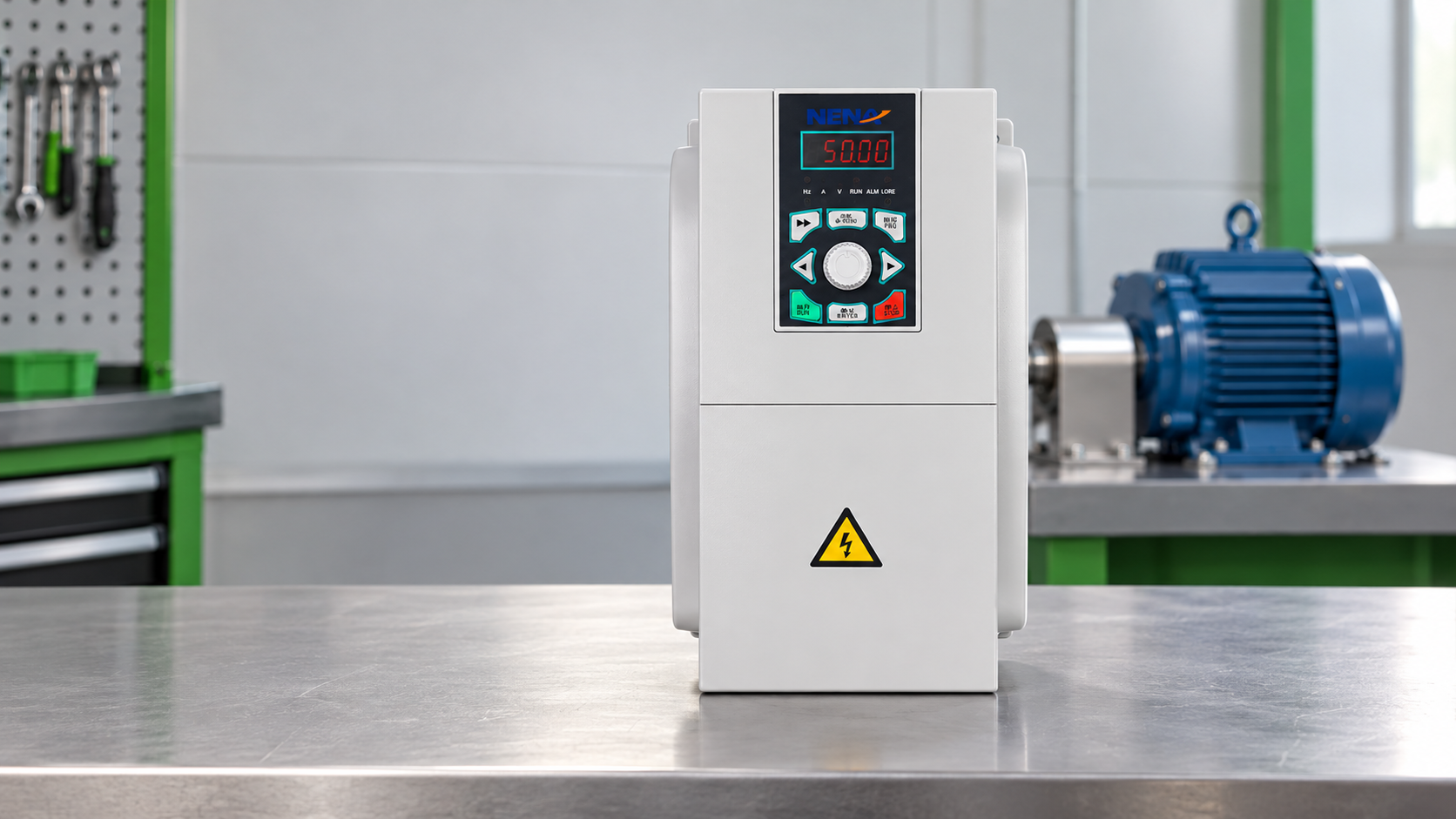
When a Suzhou maintenance supervisor found a boiler-room fan running loud at near full load, she closed the inlet damper overnight to safeguard production. Pressure fluctuations soon triggered an alarm with repeated motor restarts. Commissioning review disproved simple fan inefficiency: the root cause was a fixed-speed motor for variable demand, paired with throttling rather than speed control.
Summary: Fan power roughly varies with the cube of speed under similar system conditions: a 20% speed cut yields ~49% lower power (0.8³), though static head, leakage and minimum flow alter results. A properly selected VFD controls fan speed and maintains safe motor operation. Commission it using measured airflow, pressure, current and temperature, not estimated energy savings.
Fans move air for cooling, dust collection, ventilation, combustion, and process drying. Their demand changes with occupancy, production rate, outdoor conditions, or filter loading. The U.S. Department of Energy’s motor-systems guidance treats the motor, drive, fan, controls, and duct system as one efficiency opportunity; changing only the motor nameplate rarely addresses the full loss chain. Start by mapping the required operating points and the system curve.
Fan affinity laws explain why speed control can outperform a damper. Under similar geometry and system conditions, flow is approximately proportional to speed (Q ∝ N), pressure to speed squared (ΔP ∝ N²), and shaft power to speed cubed (P ∝ N³). These are engineering relationships, not a guarantee: a static building head, fouled filter, duct leakage, or a minimum ventilation requirement can flatten the savings.
For an illustrative baseline of 50 kW at full speed, running at 80% speed gives approximately 40 kW of flow capacity, 64% of the pressure, and 25.6 kW of fan shaft power before drive and motor losses. The practical number must come from a field test: log speed, kW, airflow, and static pressure at representative loads, then compare the control strategy after commissioning.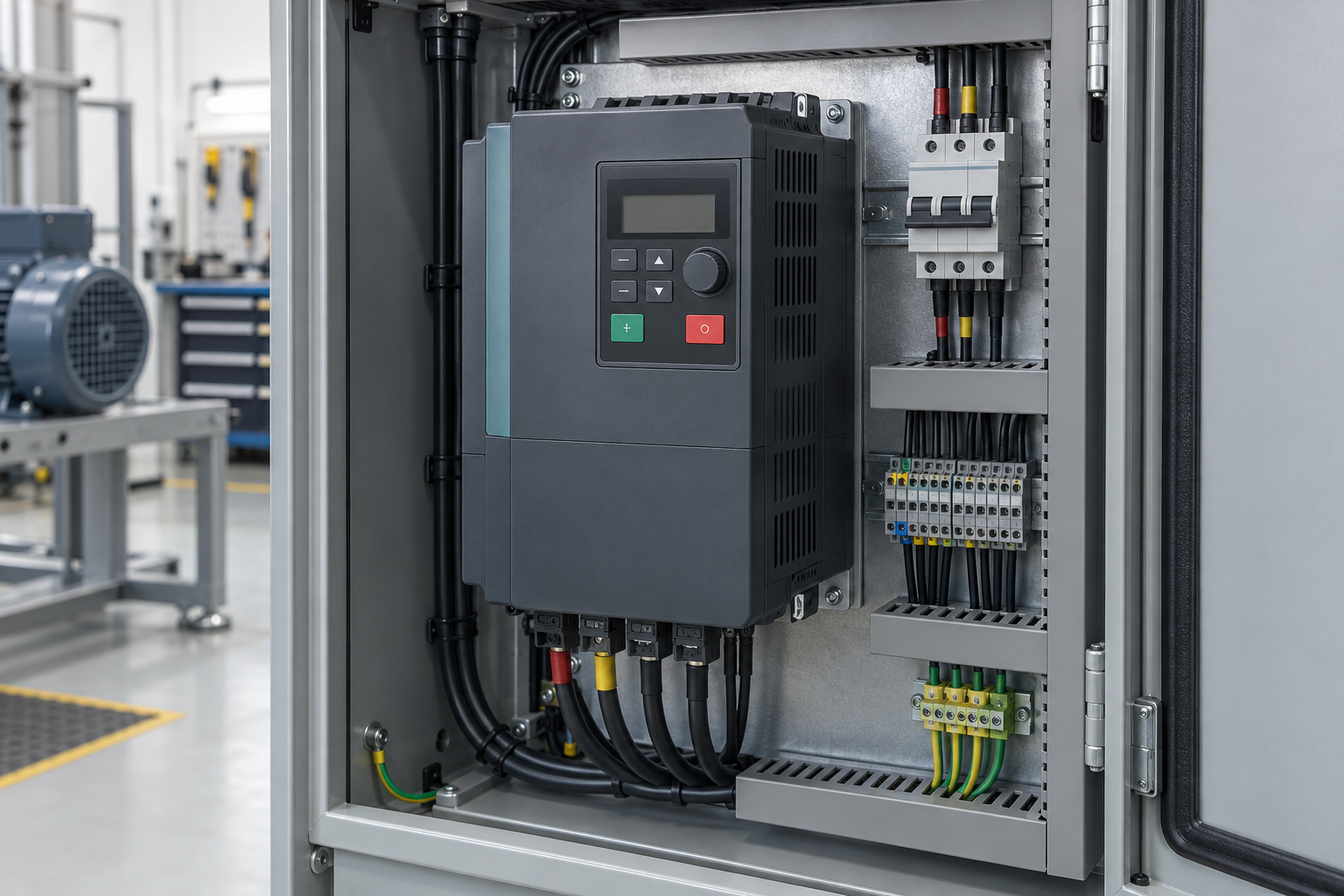
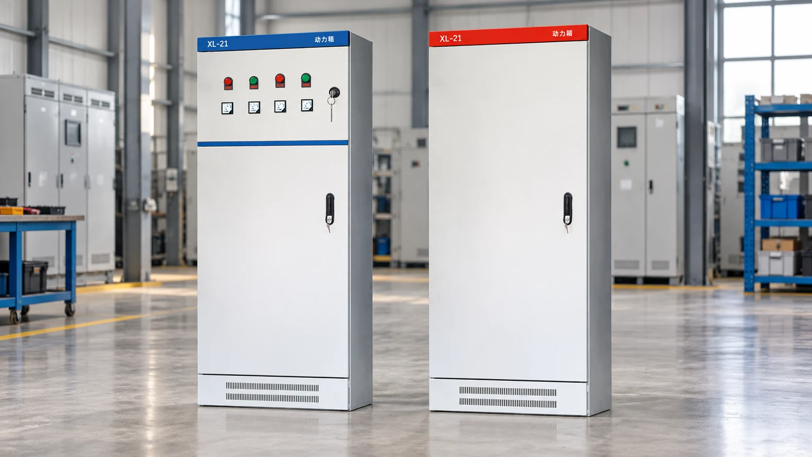
A control panel view for a fan drive installation; verify wiring, cooling clearance, and protective functions during commissioning.
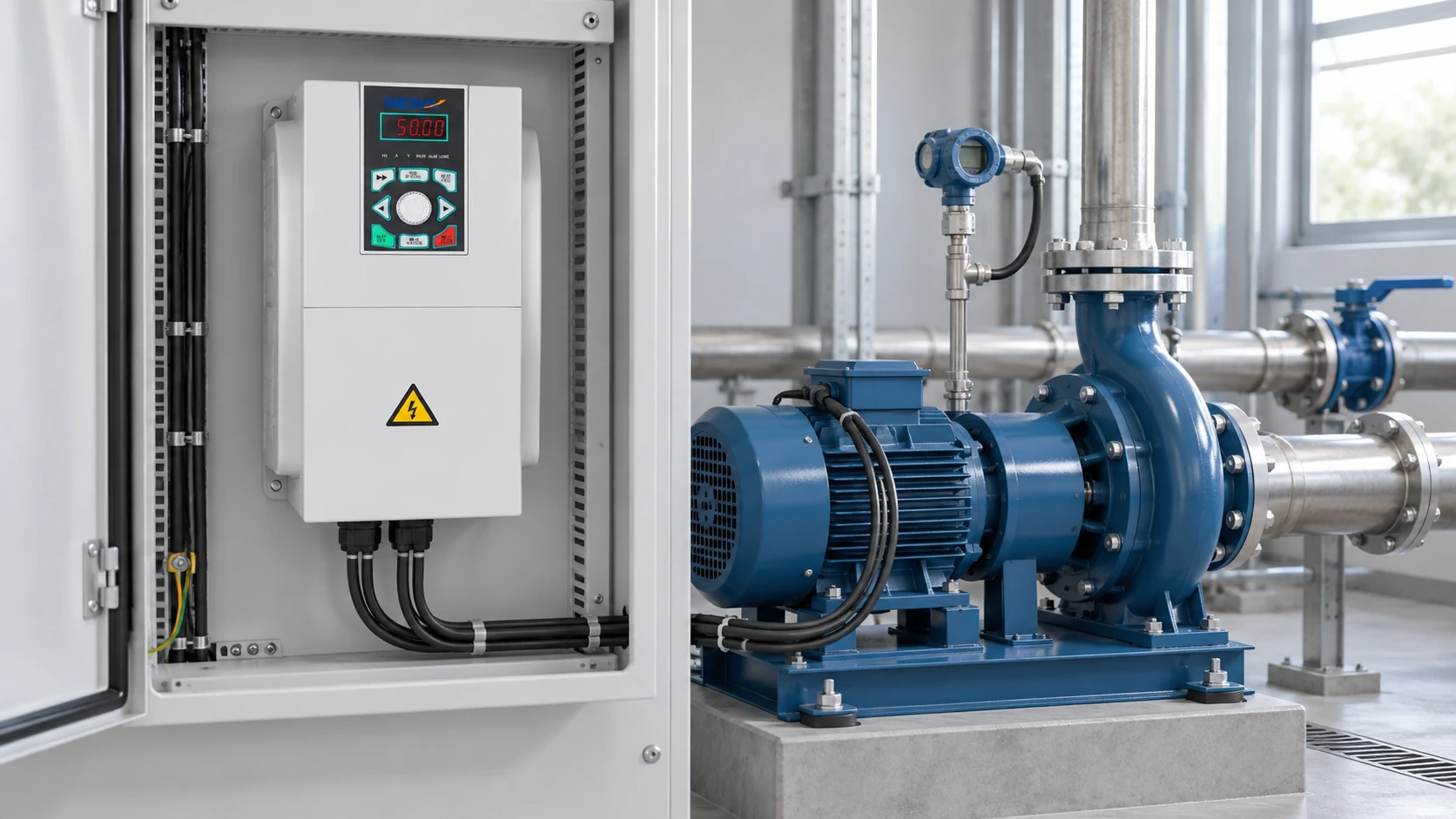
A fan inverter is the power-electronic stage that varies motor frequency and voltage so the fan can run near the required duty point. Compared with a fixed-speed motor and a throttled damper, it can remove avoidable pressure loss at part load. The best control variable depends on the process: duct static pressure for ventilation, flow for extraction, or combustion-air pressure for a boiler.
Use a feedback sensor that reflects the actual constraint, and set a safe minimum speed. A sensor placed too close to an elbow can produce unstable readings; a setpoint that is too high simply recreates throttling losses. Check bypass operation, restart behavior, fault history, and fail-safe position before accepting the calculated savings.
The drive is part of a system, not a stand-alone energy label. Motor efficiency, drive efficiency, belt or coupling losses, filter condition, and standby hours all affect total cost of ownership (TCO). A short payback estimate should include installation, controls integration, preventive maintenance, and the cost of process interruptions—not just the VFD purchase price.
Before specifying a fan VFD, record rated voltage, current, power, base frequency, motor efficiency class, service factor, starting method, fan inertia, required minimum speed, and the highest and lowest airflow/pressure points. Confirm whether the motor is centrifugal or axial, direct drive or belt drive, and whether the fan can tolerate reverse rotation during coast-down.
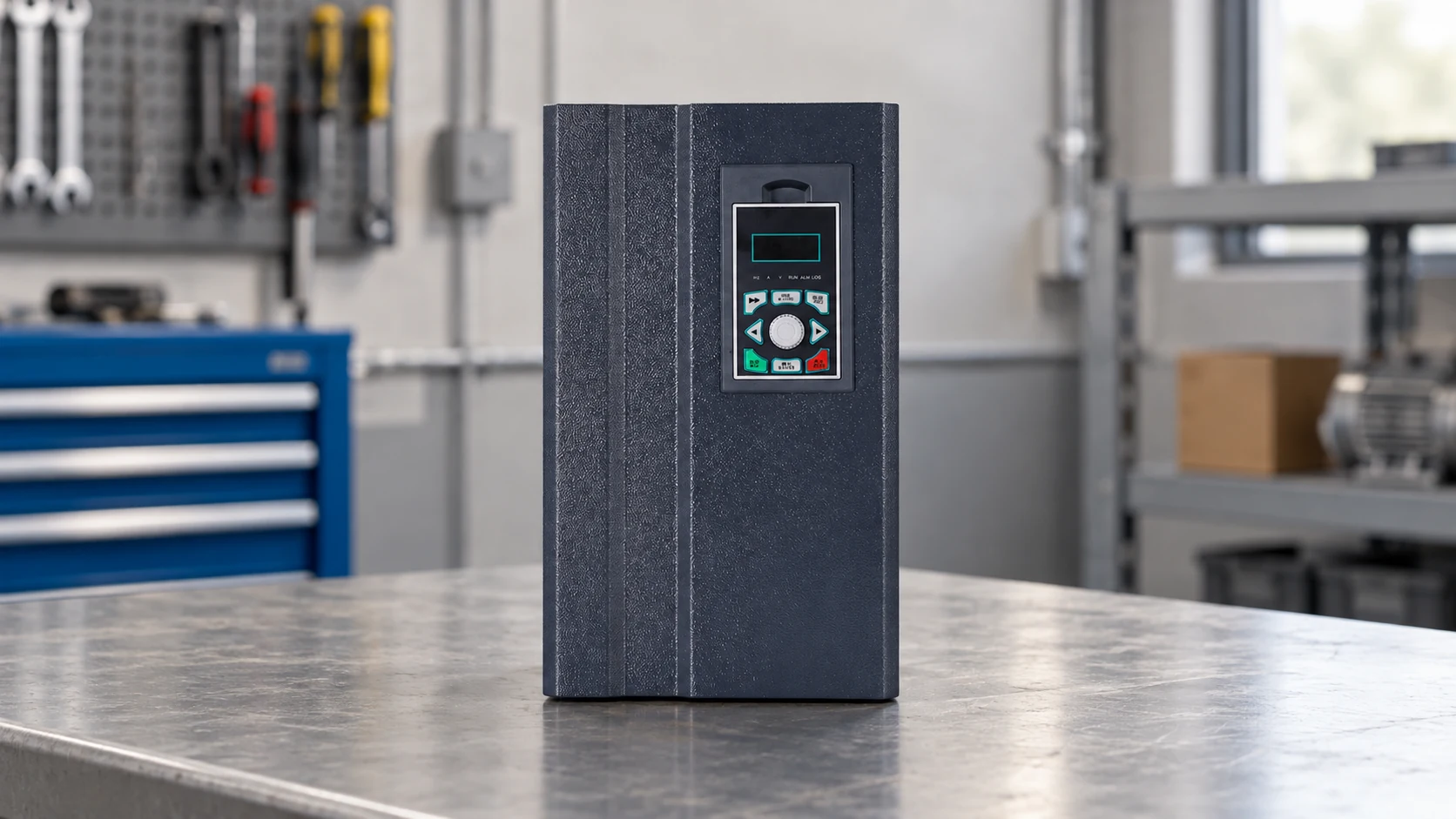
For a general-purpose option, public NH820 information lists 5.5, 7.5, and 11 kW ratings with three-phase 380 V input and applications including boiler induced-draft fans. That information is a starting point, not a sizing decision: final selection depends on motor nameplate data, overload duty, ambient temperature, cable length, braking needs, and the fan’s torque curve. Review the NH820 general-purpose inverter data with the motor and application schedule.
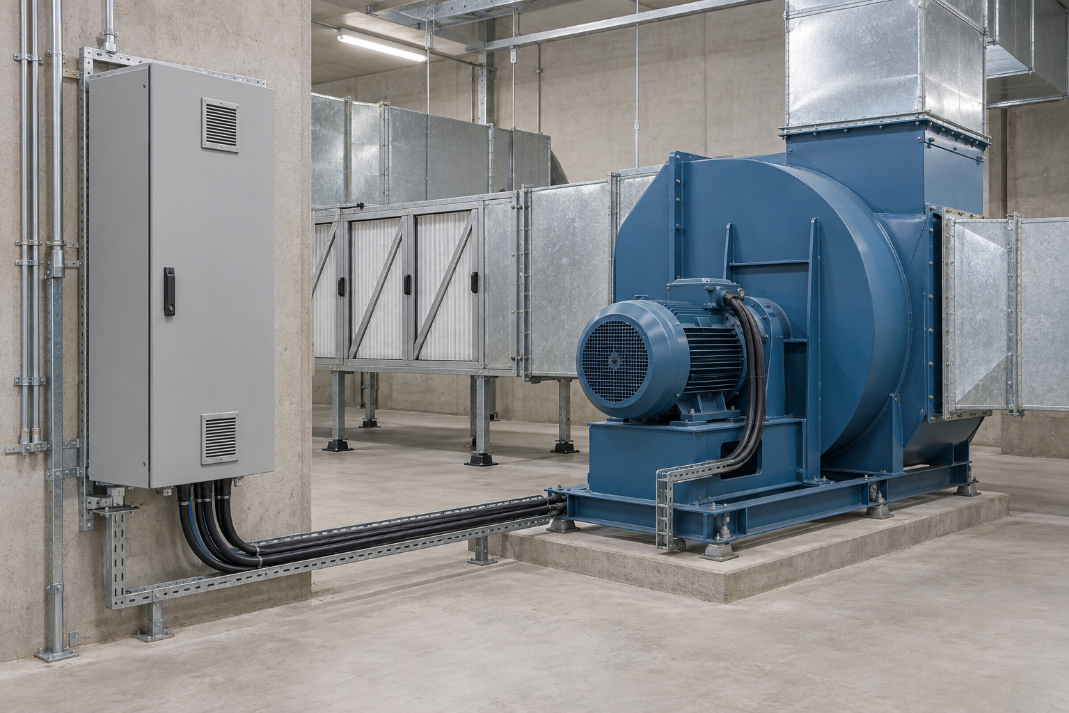
IEC 61800 is a family of standards for adjustable-speed electrical power drive systems; it addresses topics such as ratings, safety, EMC, and test methods across different parts of the family. It is not a universal certificate that every drive installation automatically holds. Ask which edition and part apply, what was tested, and whether the claim covers the drive, motor, installation, or complete system.
Electrical protection, earthing, enclosure rating, cable routing, and EMC filtering should match the destination market and installation environment. A lockout/tagout procedure is also essential during inspection and maintenance; OSHA’s control-of-hazardous-energy guidance is a useful reference for U.S.-style programs. Local electrical codes, machinery rules, and site permits may add requirements. Unsupported “certified” wording can create procurement disputes, rework, or liability even when the hardware performs well.
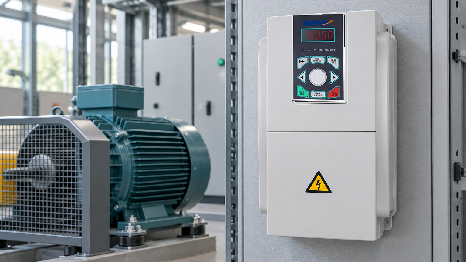
NENA/Zhejiang Xinhang Electrical presents frequency converters, inverters, soft starters, control cabinets, and distribution products. Its frequency converter range for a VFD for fan can be considered when documentation, configuration, and application support align with the project; verify the exact rating and compliance evidence for the destination market.
A VFD for a fan is an adjustable-speed drive that varies a motor’s frequency and voltage to control fan speed. It can reduce part-load energy by avoiding unnecessary damper throttling, provided the fan, motor, sensors, and system curve are correctly matched. Validate the result with measured power, airflow, and pressure.
The phrase commonly refers to voltage-source inverters (often with constant-voltage/frequency or vector control), current-source inverters, and cycloconverters or other direct-conversion designs. In commercial fan projects, a voltage-source drive is common, but the appropriate topology depends on motor type, power range, control response, and local supply. Confirm the topology and duty rating in the technical documentation.
Yes, a VFD is an inverter-based power converter that can produce variable-frequency AC for a motor. It is not automatically a general-purpose backup inverter for household loads because its output waveform, protection, grounding, and control assumptions are motor-specific. Use equipment designed and approved for the intended load.
No. A direct-drive fan can run at fixed speed or use another control method. A VFD is useful when airflow or pressure varies and the motor-fan combination supports the required speed range; check acoustic limits, motor cooling, minimum speed, and the control sequence before adding one.
The durable lesson is simple: save energy by matching fan speed to the process, then prove the saving at the shaft, sensor, and system level. When your project has confirmed duty data, contact NENA/Zhejiang Xinhang Electrical to review a documented drive and control configuration.