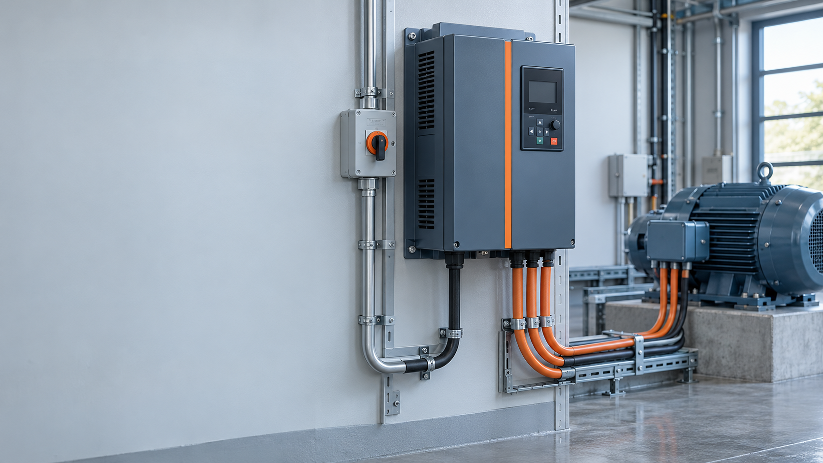
When a maintenance engineer in Suzhou, China, reduces a conveyor from 50 Hz to 35 Hz in this illustrative scenario, the motor trips within minutes. The cause is inadequate low-speed cooling, not a defective drive: the motor specification does not match continuous reduced-speed duty.
Summary:VFD controls motor speed by varying output frequency, maintaining a proper V/f ratio for torque. Synchronous speed follows n = 120f/P: a 4-pole motor reaches 1,500 rpm at 50 Hz and 1,050 rpm at 35 Hz (before slip). Specify motor, cable, protection and operating range together; verify compatibility against NEMA MG 1 or IEC 60034.
A vfd motor runs from the drive’s variable-frequency output. The AC drive first converts incoming AC to DC through a rectifier and DC link. Power switches then create a variable-frequency, variable-voltage output using pulse-width modulation (PWM). The controller changes the pulse pattern so the motor sees the commanded fundamental frequency, while the switching carrier is typically several kilohertz. Carrier frequency affects acoustic noise and losses; it is not the primary speed command.
For an induction motor, the useful first-order relationship is:
Synchronous speed (rpm) = 120 x frequency (Hz) / number of poles
Rotor speed is slightly lower because slip is needed to make torque. At rated frequency and below, a scalar V/Hz profile holds magnetic flux approximately constant: reducing frequency without reducing voltage can saturate the core, while reducing voltage too far can starve torque. Vector control adds current and flux estimation, allowing better low-speed torque and dynamic response than basic V/Hz control.
At the motor’s base frequency, the drive reaches rated voltage. Above base frequency, voltage cannot usually rise with frequency, so the motor enters a field-weakening region with decreasing available torque. Procurement specifications should therefore state continuous torque, overload duration, minimum speed, maximum speed, acceleration time, and whether regenerative braking is expected rather than listing only a maximum rpm.
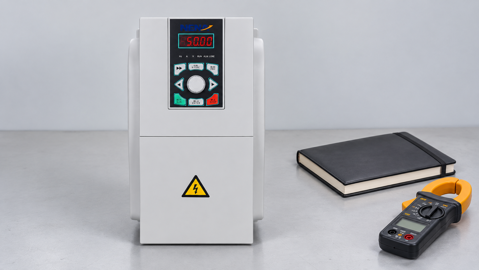
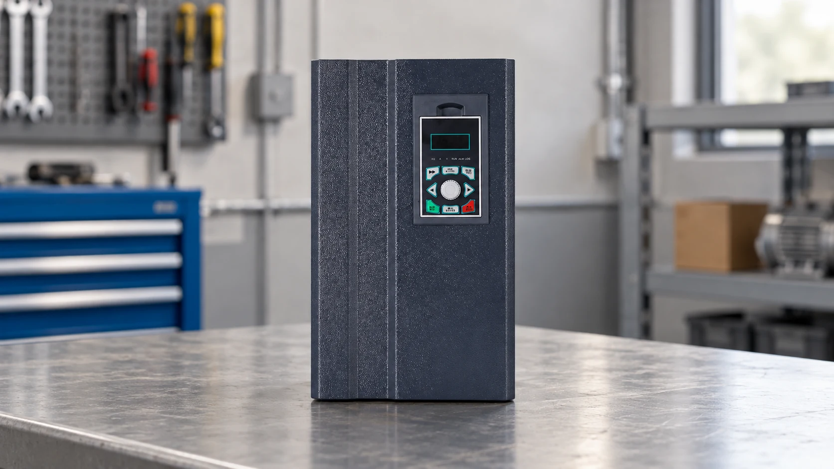
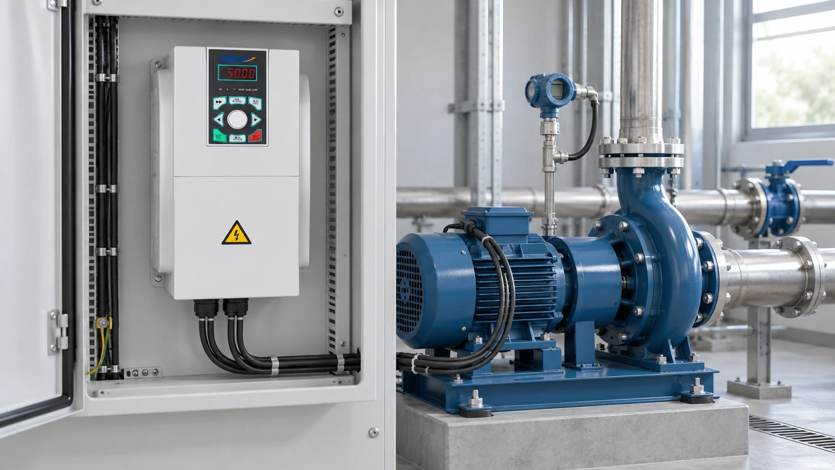
Reference-based NENA 820 product scene; illustrative only, not installation instructions.
The VFD motor drive should be selected by output current and application duty, not by an imprecise horsepower match. The nameplate full-load current, service factor, ambient temperature, altitude, and prospective short-circuit current all affect the selection. A properly specified vfd motor package treats the drive, motor, cable, and protection as one system.
An inverter duty motor is designed or qualified for the electrical and thermal stresses produced by a PWM drive. The relevant construction details can include enhanced turn-to-turn insulation, a defined withstand capability for fast voltage rise (dv/dt), independent cooling at low shaft speed, insulated or hybrid bearings, and a shaft-grounding provision. The exact package varies by motor frame, voltage, cable length, switching frequency, and application.
NEMA MG 1 Part 31 addresses definite-purpose inverter-fed motors and their insulation considerations; IEC 60034-17 and IEC 60034-25 provide guidance on converter-fed motor stresses and system interaction. These documents are not a blanket promise that every motor will survive every drive installation. Confirm the motor’s stated voltage peak, rise-time limits, permissible speed range, cooling method, and bearing protection with the supplier.
Cooling is often the hidden limit for a vfd motor. A self-cooled motor’s fan slows with the shaft, so continuous torque at 10 Hz may overheat the winding even when current appears acceptable. A separately ventilated motor, a larger frame, or a restricted low-speed torque curve can solve the problem. Conversely, oversizing without checking minimum-load behavior can reduce efficiency and make current-based protection less precise.
For long motor leads or high carrier frequencies, ask whether the installation needs a dV/dt filter or sine-wave filter. Check the motor terminal peak voltage, cable impedance, and drive filter compatibility; a filter can add voltage drop and may require drive autotuning or a revised carrier-frequency limit. Bearing-current mitigation should be evaluated when common-mode voltage, shaft voltage, or prior bearing fluting has been observed.
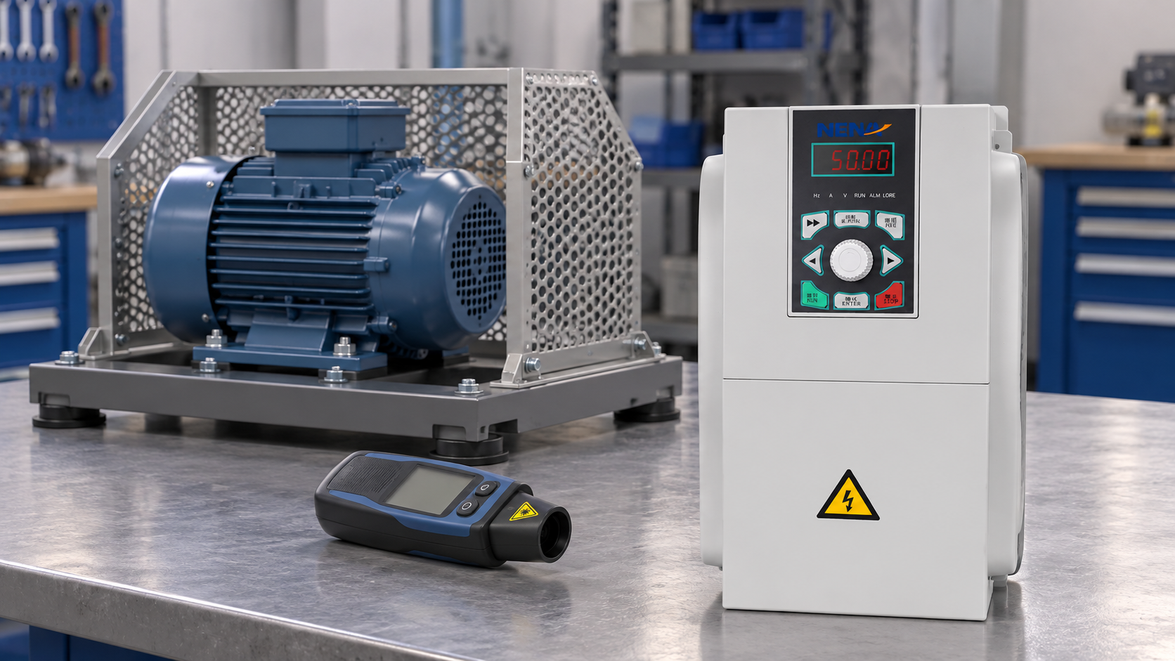
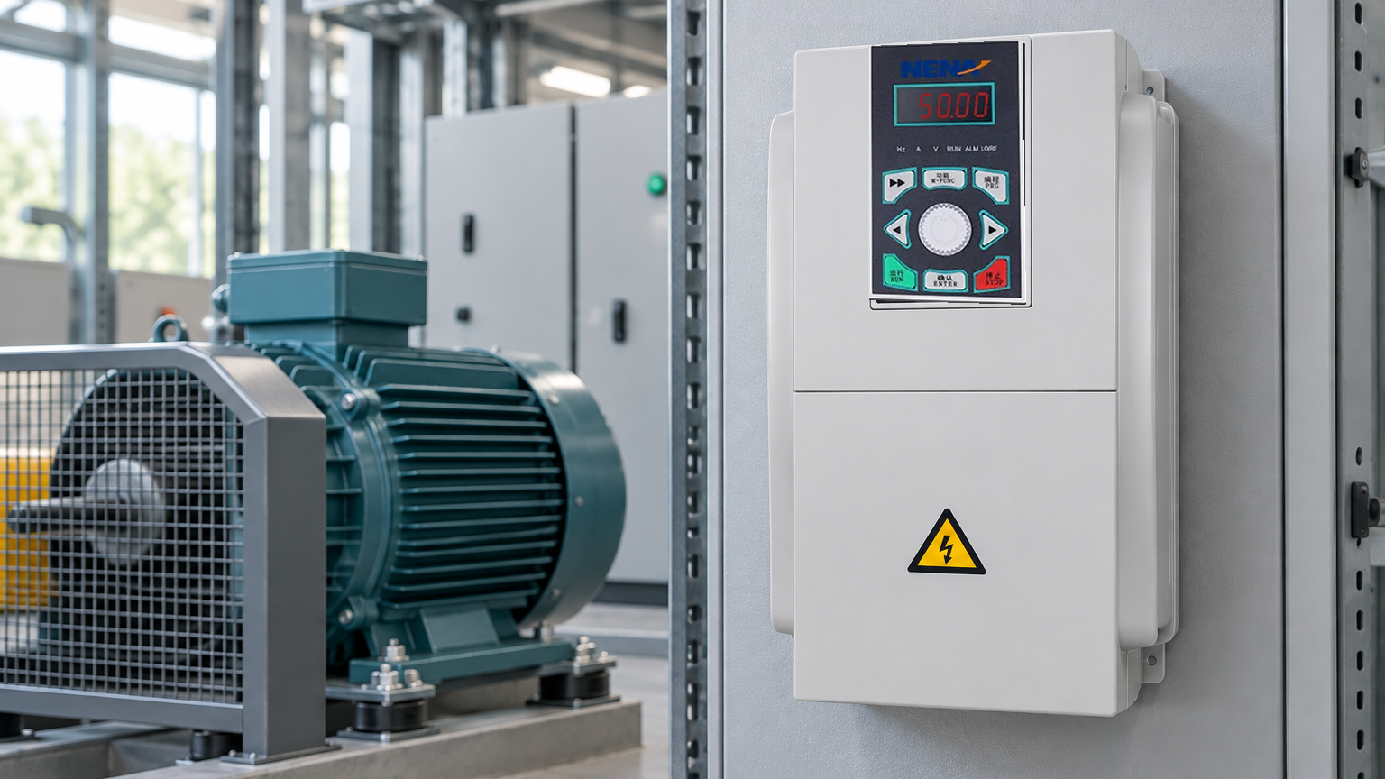
Reference-based NENA 820 product scene with an illustrative speed-test context; not installation instructions.
A vfd motor selection starts with the load profile and environment, then matches the drive and motor as a pair. This matrix is a practical screening tool for procurement and engineering reviews.
| Application dimension | Typical requirement | VFD and motor implications | Verification before order |
|---|---|---|---|
| Variable-torque fan or pump | Frequent operation below base speed | Standard V/Hz may be adequate; confirm minimum cooling and bypass needs | System curve, minimum flow, motor temperature, energy model |
| Constant-torque conveyor | High breakaway and steady torque | Vector mode, overload capacity, braking strategy, and robust coupling matter | Loaded acceleration, torque margin, ramp time, jam response |
| High-inertia centrifuge | Controlled acceleration and deceleration | DC-bus management, braking resistor or regeneration, mechanical overspeed review | Inertia calculation, stop-time test, brake duty cycle |
| Compressor or mixer | Torque can remain high at low speed | Inverter-duty insulation and independent cooling may be necessary | Pressure/torque curve, duty cycle, cooling test, current trend |
| Long cable or remote motor | Reflected-wave and common-mode exposure | Output filter, shield, grounding, and bearing-current plan | Cable length, impedance, peak-voltage limit, EMC inspection |
| Two or more coordinated motors | Same speed command, separate protection | Sum current ratings; individual overloads and engineered disconnects | Single- and multi-motor thermal tests, interlock test |
| Washdown, dust, or high ambient | Enclosure and derating constraints | Select enclosure, ingress protection, ventilation, and altitude derating together | Site survey, temperature range, IP/NEMA enclosure requirement |
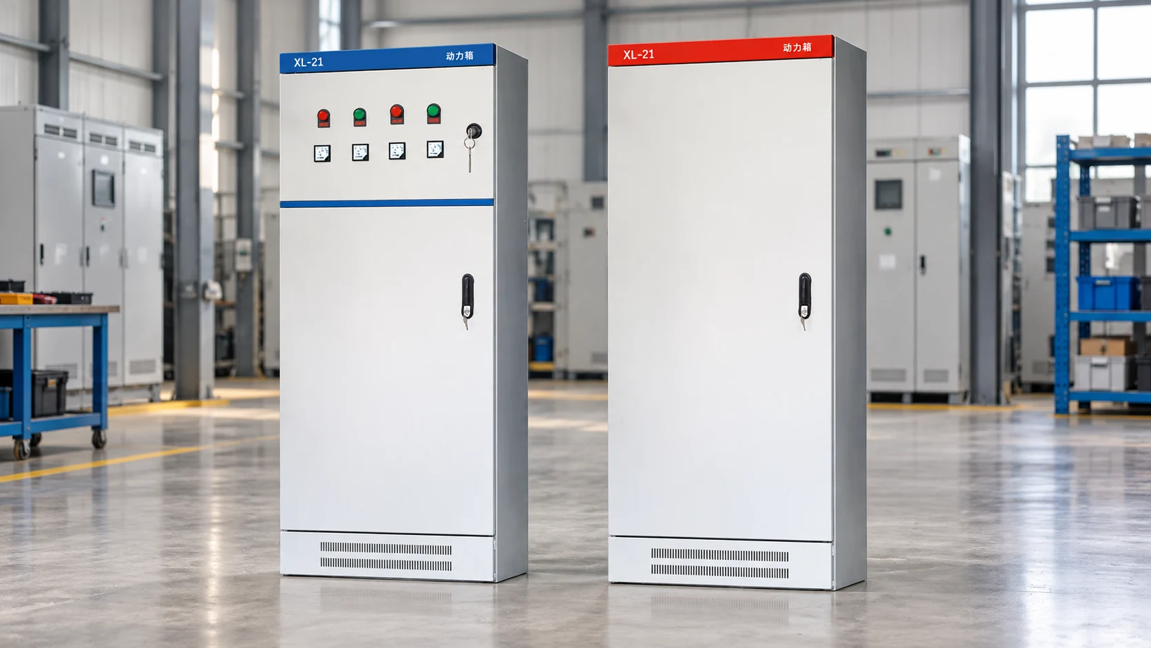
Where a packaged assembly simplifies wiring and documentation, the product catalogue is a starting point for identifying drive and control components; any complete cabinet offering must be confirmed with the supplier. The cabinet specification still needs the site voltage, fault level, heat dissipation, enclosure environment, and required documentation.
Discuss the drive-and-control specification with NENA / Zhejiang Xinhang Electrical; the right commercial comparison is the documented total cost of ownership, including energy, downtime, filters, cooling, spares, and commissioning. Share the motor nameplate and load profile with the supplier’s contact team to establish a reviewable selection basis.
Conventional drive types: VSI, CSI, PWM — not mutually exclusive; PWM is a common VSI switching method. Scalar V/Hz, sensorless/closed-loop vector are separate control modes. Specify both power conversion design and control performance requirements.
Inverters convert DC to AC; VFDs are full adjustable-speed systems with rectification, DC link, inverter, control logic, protection and UI. “Inverter” is often VFD shorthand in industrial catalogs — confirm quotes include input section, controls, enclosure and motor protection.
This motor is rated for PWM drive voltage stress, waveform, thermal and speed conditions. Key specs: insulation, independent cooling, bearing protection, cable/filter limits. Verify manufacturer limits against actual drive, cable, carrier frequency and duty — don’t rely on the label alone.
Yes, if both motors share one frequency command, size the drive for combined current with individual motor protection.
Not suitable for independent speeds or live output switching. Verify overload settings, cabling, interlocks and thermal behavior at commissioning.
The reliable speed-control principle is simple: change frequency, preserve the right flux, and prove the motor-drive pair under the real load. For a project-specific quotation, send the operating data and installation constraints through NENA / Zhejiang Xinhang Electrical contact support.