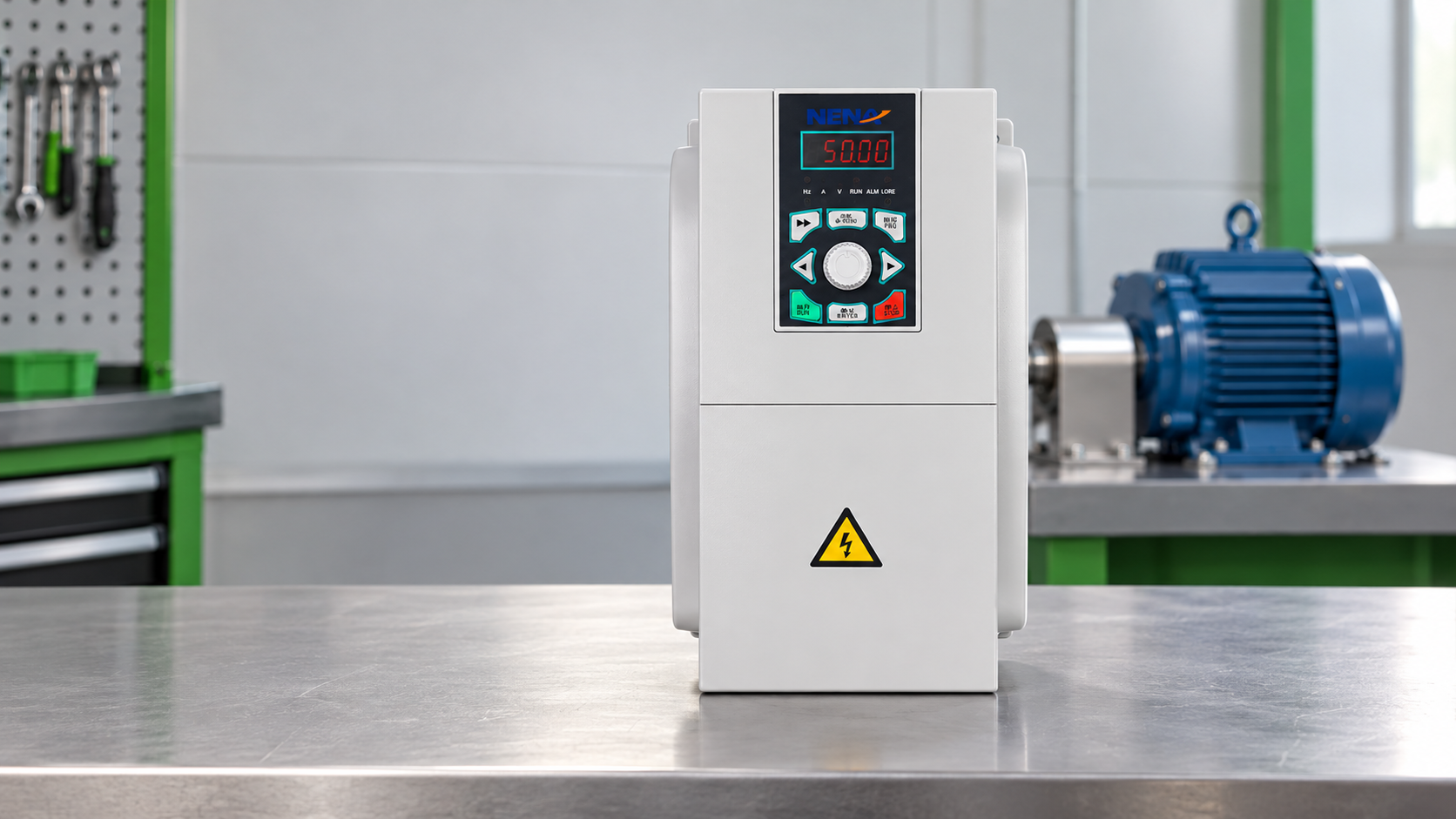
When a Suzhou maintenance supervisor adjusted a conveyor drive before morning shift, the motor tripped on overcurrent and stopped production within seconds. Changing ramp and torque settings twice did not help. A review found the motor was wired for a different nameplate voltage and the drive had been sized from kilowatts alone. The root cause was specification and commissioning—not simply a bad product.
Summary: A VFD changes frequency and voltage to an induction motor to control speed. At 50 Hz, a four-pole motor has a 1,500 rpm synchronous reference; loaded speed is lower due to slip. Match the drive to motor rated voltage, current, frequency, connection and load duty, then use qualified isolation, parameter entry and controlled tests before release.
Selecting a variable frequency drive for 3 phase motor is a system decision. The drive, motor, cable, protection and load must work together. A VFD for 3 phase motor can reduce throttling losses in variable-flow systems, but savings depend on duty.
Record the incoming supply voltage, phase count and frequency before reviewing products. Then copy the motor nameplate voltage, full-load current, rated frequency, speed, power, insulation and permitted delta/star connection. A three-phase output does not prove that a drive accepts every input arrangement, so verify the exact input specification in the manual.
Delta/star is not a preference to guess. For a motor marked 230/400 V delta/star, a 230 V output is normally paired with delta and a 400 V output with star, but that applies only to that marking and the drive’s actual output. Follow the terminal diagram and manual; never infer the connection from another motor or photograph.
Size by rated output current and overload duty, not kW alone. Pumps, fans, conveyors and high-inertia machines have different acceleration requirements. Check continuous and short-time current ratings at the real ambient, altitude, enclosure and switching frequency. A 3 phase VFD is correctly sized only when those conditions and the load duty are documented; there is no universal derating percentage.
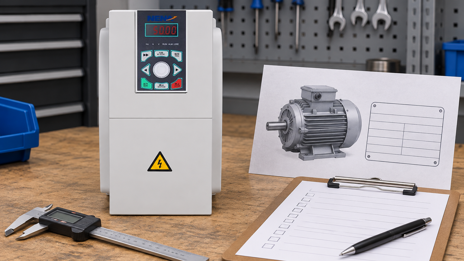
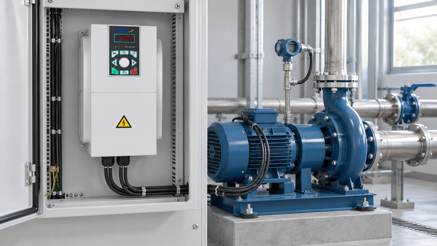
Reference-based inspection scene for an official NENA 820 context. Use the physical nameplate and exact manual; the image does not invent terminal labels or settings.
Installation belongs to qualified electrical personnel under the site’s lockout/tagout procedure. Isolate every relevant electrical and mechanical energy source, apply locks and tags, wait the specified DC-bus discharge time, and verify absence of voltage with suitable test equipment. A dark display is not proof that the DC bus is safe.
Keep the power path clear in the documentation. Incoming mains terminals, motor-output terminals, control terminals and protective earth (PE) serve different functions. PE is a protective connection, not a phase conductor. Never connect incoming mains to the drive’s output terminals, and never switch a motor contactor at the output while the drive is running unless the approved design explicitly permits it.
Follow the approved conductor, grounding, shield and residual-current-protection design. Cable length, motor insulation and switching edges can require an output reactor, dV/dt filter or sine-wave filter within the manufacturer’s limits. Disconnect the drive as instructed before an insulation-resistance (megger) test; never megger through an energized or connected VFD. IEC 61800-5-1 provides a power-drive safety scope, while local rules determine installation obligations.
Enter the motor’s actual voltage, current, base frequency and rated speed where requested. These values support the motor model, current protection and control behavior. Keep a dated parameter record for replacement commissioning.
Frequency is a command reference, not exact shaft speed. For a four-pole motor, reducing 50 Hz to 25 Hz changes synchronous speed from 1,500 to 750 rpm; loaded speed remains lower because of slip. Below base speed, a shaft fan may move less air, so sustained low-speed torque can exceed cooling capability. Confirm thermal limits and approved independent cooling when required.
Set minimum and maximum frequency, ramps, start/stop source, current limits and any boost only after reviewing the load. A short deceleration ramp on a high-inertia or overhauling load can raise DC-bus voltage; use a longer ramp or approved braking rather than disabling protection. Autotuning must follow the manufacturer’s conditions, including whether the motor may be coupled or stationary.
Before energizing, check approved connections, protective-earth continuity, guards, interlocks, emergency-stop behavior and the control circuit. With people clear and the machinery released for test, run a permitted low-speed direction check. If direction is wrong, isolate, wait for DC discharge and verify before the approved wiring or parameter change.
Ramp through the intended range under controlled conditions. Observe current, vibration, temperature, fault history and process response rather than accepting the system because the shaft turns. Confirm acceleration, deceleration and low-speed cooling; record settings and observations for handover.
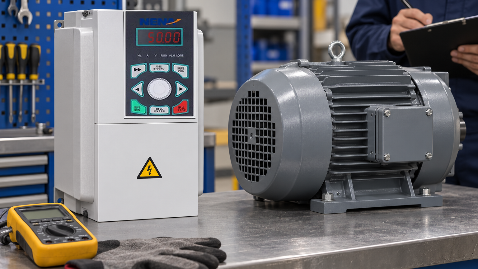
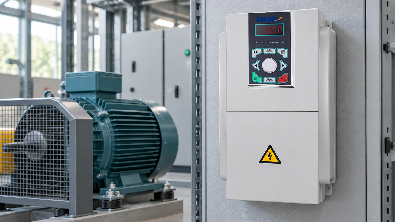
Commissioning reference image showing a guarded motor-drive test arrangement; verify direction, current, temperature and protective functions using approved procedures.
Prepare this information before comparing industrial motor-control products. Each dimension changes required current, control mode or installation evidence.
| Duty dimension | Information to collect | Selection consequence |
|---|---|---|
| Variable-flow fan or pump | Flow range, system curve, static head, operating hours | Establish minimum speed and energy case |
| Loaded conveyor | Starting torque, inertia, cycle frequency, stops | Check overload, acceleration and braking |
| Sustained low-speed operation | Torque demand, cooling and minimum speed | Confirm thermal limits or independent cooling |
| Long motor cable | Length, insulation, routing and switching frequency | Apply cable limit and filter requirements |
| Several motors | Individual currents, duty, protection and control | Assess summed current, overloads and same-command behavior |
IEC 61800 covers adjustable-speed electrical power-drive systems. IEC 61800-5-1 addresses electrical, thermal and energy safety; IEC 61800-3 addresses electromagnetic compatibility. IEC 60034 covers rotating electrical machines, with the applicable part selected for the motor, rating and converter-fed service. These are standards with defined scopes, not blanket proof that a complete machine is compliant.
NEMA MG 1 addresses motors and generators and includes guidance relevant to inverter-fed motors. The edition and applicable clauses matter. A NEMA reference is not a product certification by itself, and a drive manual does not certify the complete panel, machine safeguards or destination-market installation.
Request declarations, test evidence and installation conditions matching the destination market, intended use and quotation claims. Unsupported certification language can delay acceptance or force redesign. Keep motor, drive and machine documentation traceable to the exact model and revision.
Usually, provided motor, drive input/output and load are compatible. Verify nameplate voltage, current, frequency, insulation, cooling and speed range. Older motors, long cables and sustained low speed may require evaluation or approved filtering.
A VFD is an electronic converter that creates a controlled-frequency, controlled-voltage motor output. It regulates speed, acceleration and deceleration within motor and load limits. Installation still requires qualified personnel and the manufacturer’s instructions.
Start with nameplate current and overload duty, then check rated output under actual ambient, altitude and switching conditions. Kilowatts alone are insufficient; no universal derating percentage applies. Use current tables and document the margin.
For continuous variable speed, a correctly matched VFD is often the relevant option; for fixed-speed duty needing a gentler start, a soft starter may be more appropriate. The best choice depends on torque, speed range, cooling, starts per hour, braking and process control. Compare the complete duty rather than choosing by product label.
Reliable speed control begins with a matched system, not a guessed setting: nameplate first, safe isolation second, measured commissioning third. When duty is documented, NENA can review a suitable configuration; contact the technical team with the motor nameplate, supply details and operating profile.