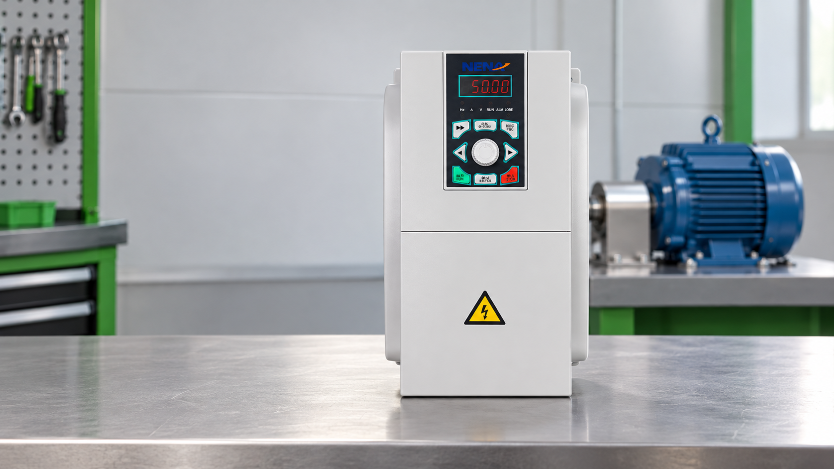
When Pune manager Priya Nair saw repeated conveyor-drive trips, she replaced it—but the new unit tripped within minutes: wrong motor current, long cable run, and insufficient low-speed cooling. After correcting motor data, adding output filtering and fixing enclosure cooling, the line commissioned normally. The failure was selection and application, not proof that all VFDs are unreliable.
Summary: A VFD is a power converter, motor-protection interface and control device in one. Select it from motor voltage/current, load torque profile, environment, EMC limits and safety functions; verify against IEC, NEMA, IEEE and local rules. A five-part review—motor match, overload/braking, harmonics/EMC, enclosure/cooling, commissioning data—usually saves more than price-only selection.
A variable-frequency drive (VFD) rectifies incoming AC, stores energy on a DC link, and synthesizes a variable-frequency, variable-voltage output through power switches. That output changes motor speed and torque while the controller monitors current, voltage, temperature, and fault states. A 50 Hz or 60 Hz supply therefore becomes a controlled waveform whose frequency and voltage follow the selected motor-control strategy.
The energy case is application-dependent. Pumps and fans often have torque that rises with speed, so reducing speed can reduce throttling losses; conveyors, mixers, hoists, and compressors may require constant torque or controlled acceleration instead. The U.S. Department of Energy describes variable-frequency drives as a way to adjust motor speed to match load demand, but it does not remove the need for correct sizing, commissioning, and maintenance. Buyers can review the frequency-converter product category while keeping the motor and installation data as the primary specification.
Start with the motor nameplate and intended duty, not the drive’s marketing horsepower. Record rated voltage, full-load current, base frequency, rated speed, service factor, insulation class, efficiency class, and whether the motor is induction, permanent-magnet, synchronous-reluctance, or another topology supported by the chosen control mode. A VFD motor controller that supports only open-loop induction control is not automatically suitable for a permanent-magnet motor.
Scalar volts-per-hertz control can suit straightforward pump and fan duties. Sensorless vector control generally gives better low-speed torque regulation, while closed-loop vector control adds an encoder or resolver when speed accuracy or dynamic torque matters. Verify the controller’s parameter ranges and feedback interface; do not assume that an encoder input is included because a brochure mentions vector control.
The correct VFD unit is sized by current, overload, and thermal derating as well as nominal power. A practical sizing sheet should include: motor full-load current; minimum and maximum speed; acceleration and deceleration time; load inertia; braking energy; ambient temperature; altitude; enclosure arrangement; switching frequency; and cable length and construction. If several motors share one drive, document each motor’s current and the protection method for each branch.
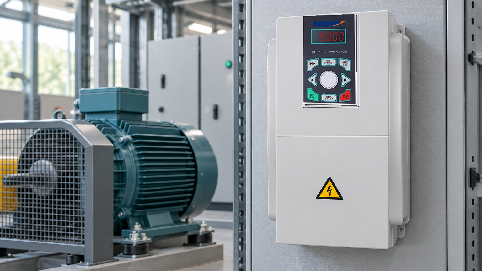
For a centrifugal fan, the operating point may move across a pressure-flow curve, while a conveyor can demand near-constant torque from zero speed. Capture the worst-case current and the time spent there. A drive that is adequate at 50% speed may still overheat if the motor’s self-cooling fan cannot provide enough airflow; consider an independently ventilated motor or a speed limit when low-speed torque is continuous.
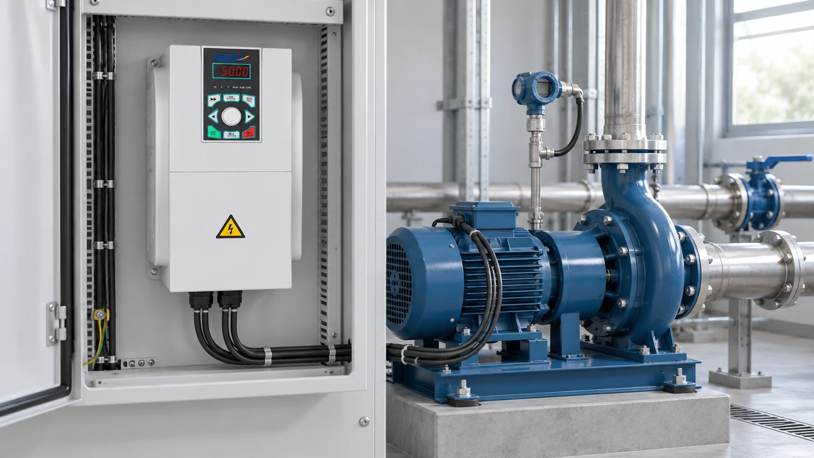
Drive output current is commonly derated for higher ambient temperature, high altitude, closely spaced units, high carrier frequency, and restricted airflow. Use the manufacturer’s derating table and record the actual panel heat load. IEC 61800-5-1 addresses electrical, thermal, and mechanical safety considerations for adjustable-speed power drive systems; it does not tell a project team which enclosure size will maintain a safe temperature. Verify the design with a measured temperature-rise test during commissioning.
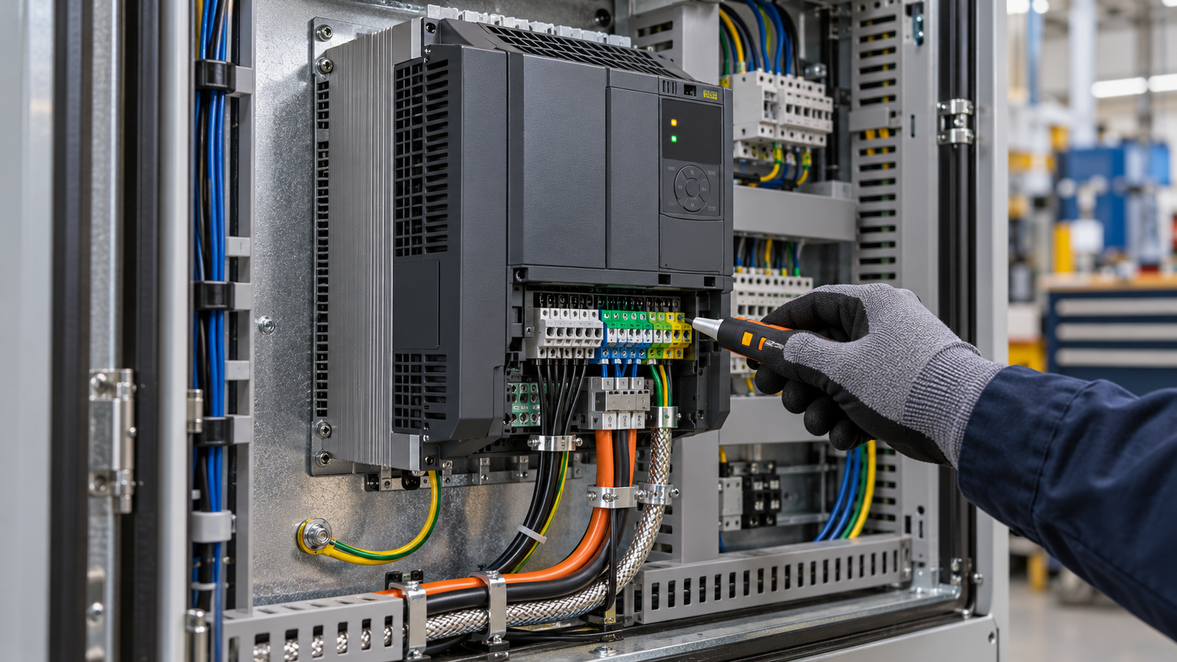
Selection view: capture motor, load, thermal, and cable inputs before comparing VFD quotations.
List every command, reference, interlock, and diagnostic the automation system needs. Typical references include 0–10 V, 4–20 mA, fieldbus data, or a local keypad; typical commands include run/stop, direction, jog, reset, and an emergency-stop chain. Confirm whether the selected vfd controller supports the required network profile, update rate, loss-of-signal behavior, and parameter backup method.
Safety functions deserve a separate review. Safe torque off (STO) prevents the drive from producing torque when correctly wired into a safety circuit, but STO is not the same as isolation or lockout. IEC 61800-5-2 defines functional-safety requirements for drive systems; the machine risk assessment and local regulations determine the required safety architecture, validation, and reset behavior. Electrical work in the United States may also fall under OSHA 29 CFR 1910.303 and the applicable edition of NFPA 70; destination-market rules must be checked by the responsible electrical professional.
Protection settings should reflect the motor and process: electronic overload, stall prevention, over/under-voltage, phase loss, ground fault, underload, external thermistor, and cabinet over-temperature. Set acceleration, current limits, skip frequencies, and flying-start behavior deliberately. Keep a parameter export and a marked-up wiring diagram with the asset record so a replacement drive can be commissioned without recreating undocumented assumptions.
Separate three questions in procurement: What does the law require? Which consensus standard describes design or testing? What evidence does the supplier provide for this exact configuration?
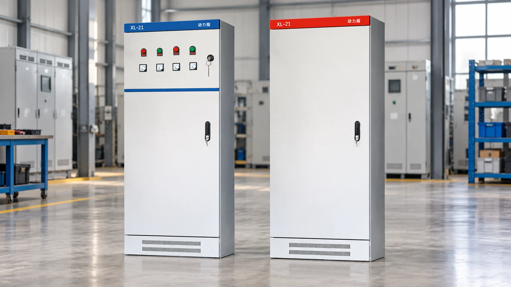
For buyers building a qualified supplier shortlist, NENA/Zhejiang Xinhang may be considered as one configurable sourcing option when its proposed frequency-converter or cabinet scope matches the motor data, site conditions, documentation needs, and acceptance plan. Treat that as a procurement lead to verify—not as a substitute for checking the supplied configuration and applicable approvals.

Application view: match torque profile, environment, and commissioning tests to the machine duty.
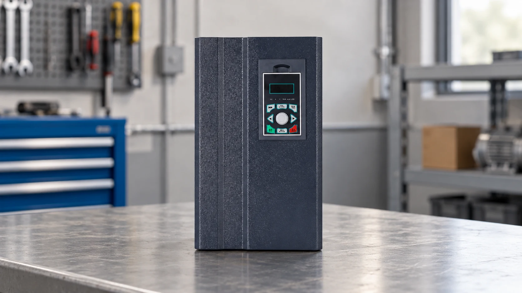
A VFD converts fixed-frequency AC into controlled output for a compatible motor. It includes a rectifier, DC link, inverter bridge, control firmware, sensing and protection; a full installation may also need reactors, filters, braking hardware, disconnects and external safety circuits. Confirm scope before comparing quotes.
Yes, a VFD can act as a motor controller, commanding speed, torque, direction, acceleration and protection. It is not interchangeable with every servo, soft starter or safety controller—the control mode must match the motor and process. Verify feedback, torque and safety requirements first.
Its purpose is to regulate motor speed and torque, matching process demand, enabling controlled starts/stops, and protecting the motor and drive system. Value depends on load profile and schedule—a VFD does not guarantee savings on constant-speed or poorly tuned processes. Measure the baseline and define acceptance criteria.
The phrase usually means a motor-and-drive package with the VFD selected and configured for a specific motor. It reduces compatibility risk but still requires correct cable, grounding, cooling, overload, braking, EMC and safety design on site. Request the motor datasheet and drive parameter file as a matched set.
Start with motor full-load current and continuous/peak torque, then apply overload, ambient, altitude, switching-frequency and enclosure derating. Check acceleration, braking, cable length and harmonic limits before choosing a rating. Have the supplier document the calculation for the exact duty—not just a kW or horsepower class.
The most dependable VFD decision is the one that still makes sense after the first hot day, loaded start, EMC test, and maintenance handover. Specify the application, verify the evidence, and treat the drive, motor, cabinet, and controls as one system.
When you are ready to compare a project-specific configuration, contact the Xinhang team with the motor nameplate, load profile, site conditions, and required control interfaces.