There is no universal minimum speed of a motor with a VFD. The safe continuous limit is the lowest speed at which the motor can deliver the required torque without exceeding its thermal limits, the drive can maintain suitable control, and the driven machine still operates correctly. A drive that accepts a very low frequency command does not automatically make the motor suitable for sustained operation there. Set the minimum from the motor’s permitted operating envelope, application requirements and a documented commissioning test—not from a blanket 10 Hz or 20 Hz rule.
This guide focuses on three-phase induction motors. Permanent-magnet and other motor types need their own drive compatibility and control review. For basic selection, start with our motor inverter selection guide; the discussion below concentrates on establishing the lower operating boundary.
For an induction motor, synchronous speed is ns = 120 × f / p, where ns is in revolutions per minute, f is the drive output frequency in hertz, and p is the number of motor poles. This describes the rotating magnetic field. The shaft runs below synchronous speed during normal motoring because slip is needed to produce torque.
| Output frequency (Hz) | Four-pole synchronous speed (RPM) | Meaning for application review |
|---|---|---|
| 50 | 1,500 | Reference frequency in this example; verify the motor nameplate |
| 25 | 750 | Half the synchronous speed; not proof of half the heating |
| 10 | 300 | Requires explicit low-speed load and cooling assessment |
| 5 | 150 | Control performance and continuous torque capability need particular scrutiny |
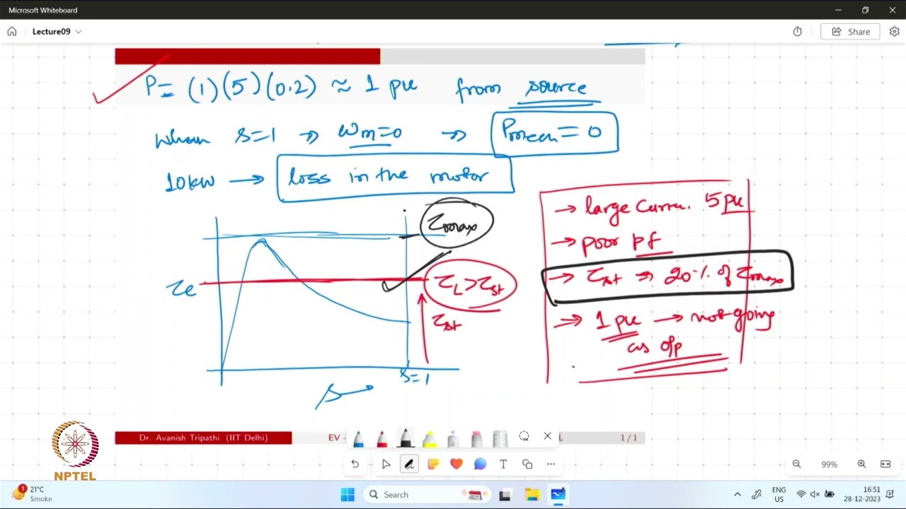
These calculated values are illustrative, not recommended minimum settings. The induction-motor principles are covered in the NPTEL IIT Delhi lecture embedded below. For an explanation of the frequency-to-speed relationship in a complete drive system, see how a VFD controls motor speed.
Suppose a four-pole motor is rated 1,450 RPM at 50 Hz. Multiplying its rated speed by 10/50 gives 290 RPM as a rough planning estimate at 10 Hz. It is not a guaranteed loaded shaft speed: slip changes with torque and control mode. If an application requires an accurate shaft speed, obtain suitable feedback or validated drive estimation rather than treating the frequency display as a tachometer.
| Limit | What may go wrong | What to establish before approval |
|---|---|---|
| Motor thermal capability | Insufficient cooling during sustained loaded operation | Motor torque-speed rating, cooling arrangement and temperature monitoring |
| Drive control capability | Poor speed regulation, unstable torque or inadequate breakaway | Supported control mode, motor identification and feedback requirements |
| Driven-machine requirements | Inadequate flow, lubrication, conveying or product quality | Machine manufacturer’s minimum operating conditions |
| System behavior | Resonance, control hunting or repeated low-speed cycling | Loaded test results, excluded speed bands and process-control settings |
The operating minimum must satisfy all applicable limits. A process minimum above the motor’s thermal minimum still governs the application. Conversely, a machine that can move slowly does not prove that its motor can remain there continuously.
Many industrial motors use a shaft-mounted cooling fan. As speed falls, that fan’s cooling effectiveness declines. At the same time, a constant-torque load can still require substantial current. Lower mechanical output therefore does not establish a proportionate reduction in motor heating. Natural Resources Canada’s electric-motor reference guide discusses reduced cooling, low-speed derating and forced ventilation.
Separate three duties in the specification: brief passage through low speed during acceleration, occasional short positioning or jogging, and continuous low-speed production. They create different thermal demands. Also consider a loaded restart after the motor is already hot. A successful cold start is weak evidence for a duty involving repeated starts and long low-speed runs.
Possible engineering responses include reducing allowable torque, using a motor with a documented wider constant-torque range, adding an approved independently powered cooling arrangement, or changing the mechanical ratio. None should be selected from a generic internet frequency limit. If separate ventilation is required, include monitoring and a response to loss of ventilation in the control review.
Do not solve an overheating problem by raising the drive’s overload limit or disabling a sensor. First check the actual load, motor data, cooling condition, parameter setup and temperature evidence. An enclosure surface reading alone does not establish the internal winding temperature. Use the motor manufacturer’s accepted measurement method and limits.
A conveyor carrying material may need almost the same shaft torque at low speed as at normal speed. Since mechanical power equals torque multiplied by angular speed, reducing speed can reduce output power while leaving a substantial torque demand. This is why a small kW reading can be misleading when deciding whether a loaded motor is thermally comfortable.
Many centrifugal pump and fan applications have a decreasing torque requirement as speed falls. Under ideal affinity-law assumptions, torque varies approximately with speed squared and shaft power with speed cubed. Actual systems also have static head, operating limits and efficiency changes. The Natural Resources Canada’s motor reference guide distinguishes load behavior and warns about operating problems caused by excessive slowing.
For a pump, reducing frequency until the motor runs quietly may still produce too little head or flow. For a fan, a minimum ventilation requirement can govern before the motor limit is reached. For a conveyor, inadequate breakaway torque may appear only when the belt is fully loaded. Obtain the driven-machine limits and test the real operating case. Our pump VFD selection guide explains the broader pump-system checks.
Scalar voltage/frequency control and vector control do not provide identical behavior at very low speed. Suitability depends on the particular drive, motor identification, tuning, load and feedback arrangement. A brochure statement such as “vector control” is insufficient evidence for a demanding continuous low-speed specification.
Ask the supplier to distinguish starting torque, steady low-speed torque, speed accuracy and zero-speed holding. Those are separate requirements. If the application needs torque at standstill, precise position or suspended-load control, it requires a dedicated engineering and safety review. Do not infer those capabilities from the drive’s lowest selectable frequency.
Before testing, verify the motor nameplate data entered into the drive and the permitted identification procedure. Some procedures rotate the shaft, making guarding and mechanical conditions important. Excessive torque boost can increase heating; arbitrary adjustments are not a substitute for correct motor data. Follow the actual drive manual and record the approved parameter set.
Never intentionally run beyond a manufacturer’s limit to discover where damage begins. Commissioning confirms the proposed operating envelope; it does not replace design evidence. If temperature keeps rising, torque becomes unstable or process output becomes unacceptable, stop the evaluation according to the agreed procedure and review the cause before extending the test.
A minimum-frequency parameter is also not an isolation or safety function. A run command, analog signal failure or automatic restart setting can change behavior unexpectedly. Service work requires the site’s energy-control procedure, including stored energy. OSHA explains the risks of unexpected starting and hazardous-energy release; local requirements and the equipment instructions govern the actual task.
Provide the motor nameplate and cooling method, supply voltage and phase, base frequency, required shaft-speed range, torque at the lowest speed, continuous operating duration, feedback requirements, cable length, enclosure environment and the driven machine’s restrictions. Describe what happens during starting, stopping, power loss and a lost speed-reference signal.
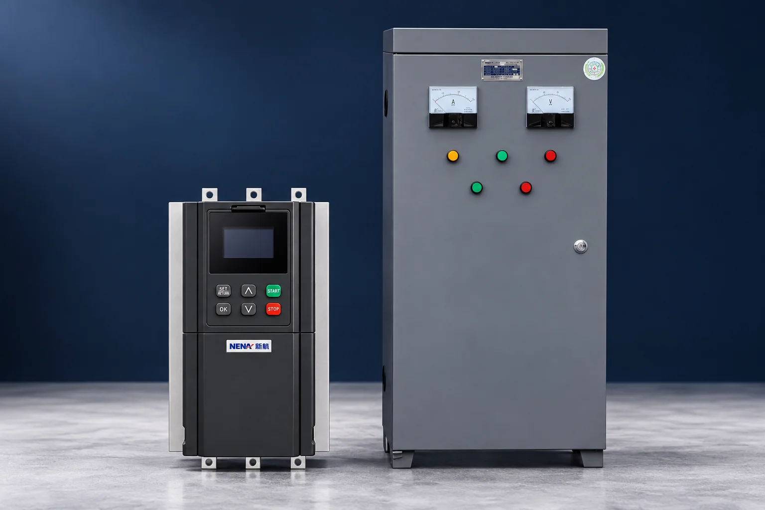
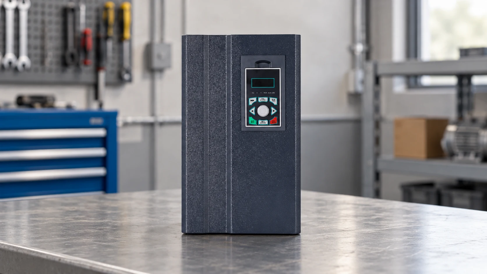
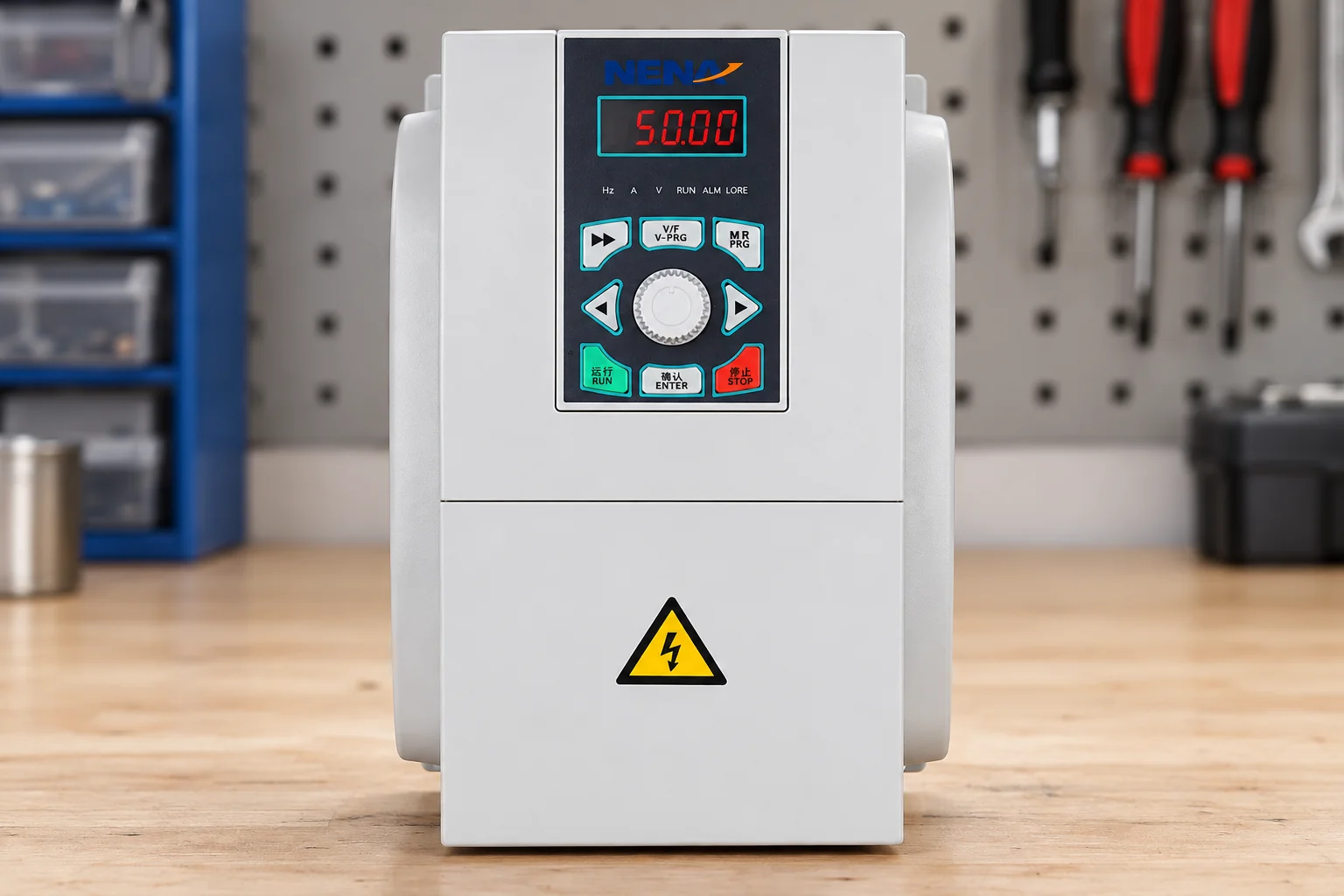
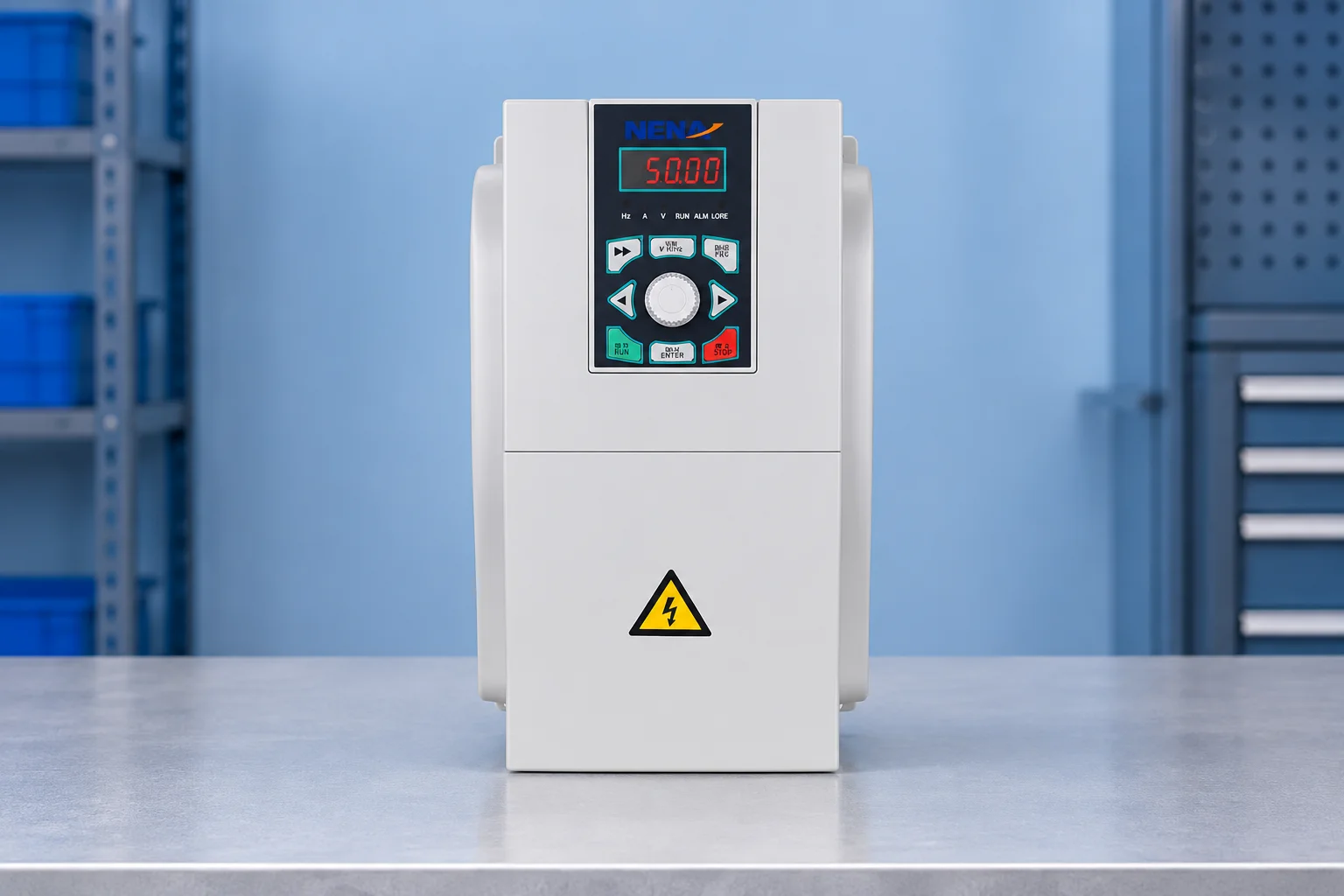
For a relevant product discussion, NENA’s general-purpose vector-control inverter is one starting point. Request the exact model’s motor compatibility, current and overload ratings, derating information and low-speed performance evidence. This article does not assign a minimum frequency or continuous torque guarantee to that product.
If the desired machine speed is very low, ask whether a gearbox or different mechanical ratio would let the motor operate in a more suitable range. Compare the effect on output torque, maximum speed, efficiency, mechanical loading and maintenance. The correct answer may be a different motor-drive-mechanical combination rather than a more aggressive parameter setting.
The following NPTEL IIT Delhi lecture provides educational context for induction-motor speed control. It is independent of NENA and does not certify a particular product or installation.
Watch the lecture on YouTube — NPTEL IIT Delhi
Possibly, but frequency alone cannot establish suitability. Confirm the motor’s permitted torque-speed duty, cooling, drive control performance and the machine’s process limits, then validate the intended loaded operation.
It gives 150 RPM synchronous speed for a four-pole motor. An induction motor’s loaded shaft speed differs because of slip. Pole count and control performance also matter.
Not by itself. Extra drive current capacity does not restore shaft-fan cooling or raise the motor’s permitted thermal duty. Review the motor, load and cooling arrangement together.
No. A conventional soft starter manages starting and possibly stopping voltage; it does not provide normal continuous variable-frequency speed control.