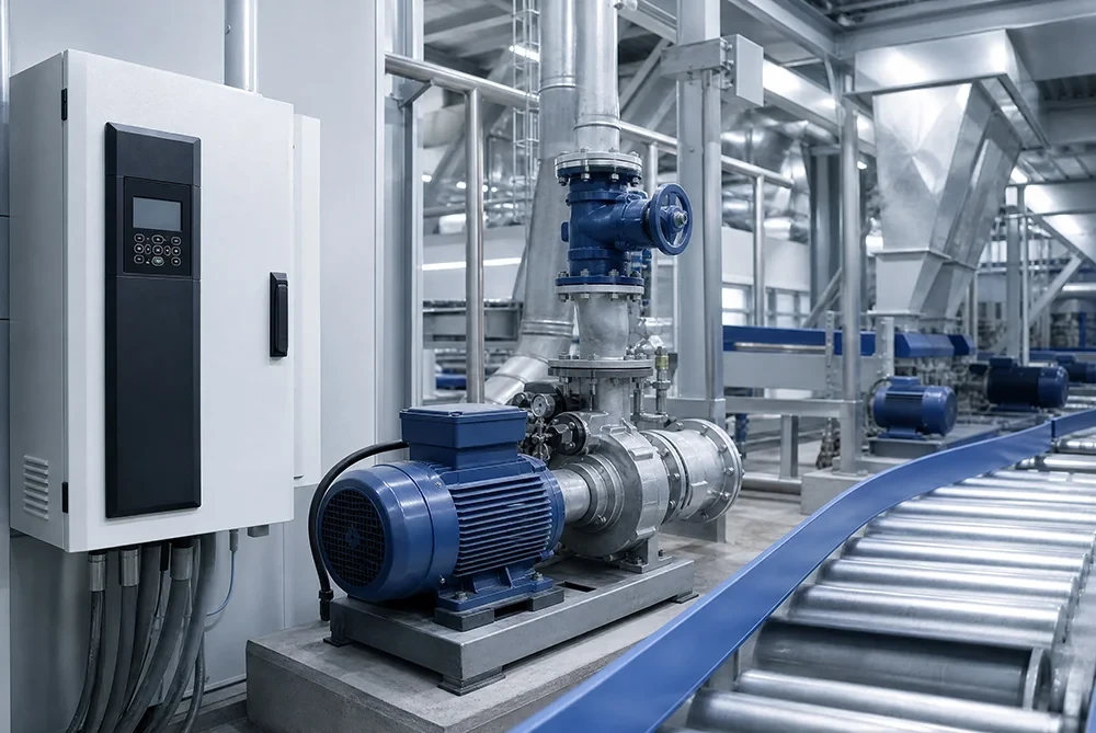
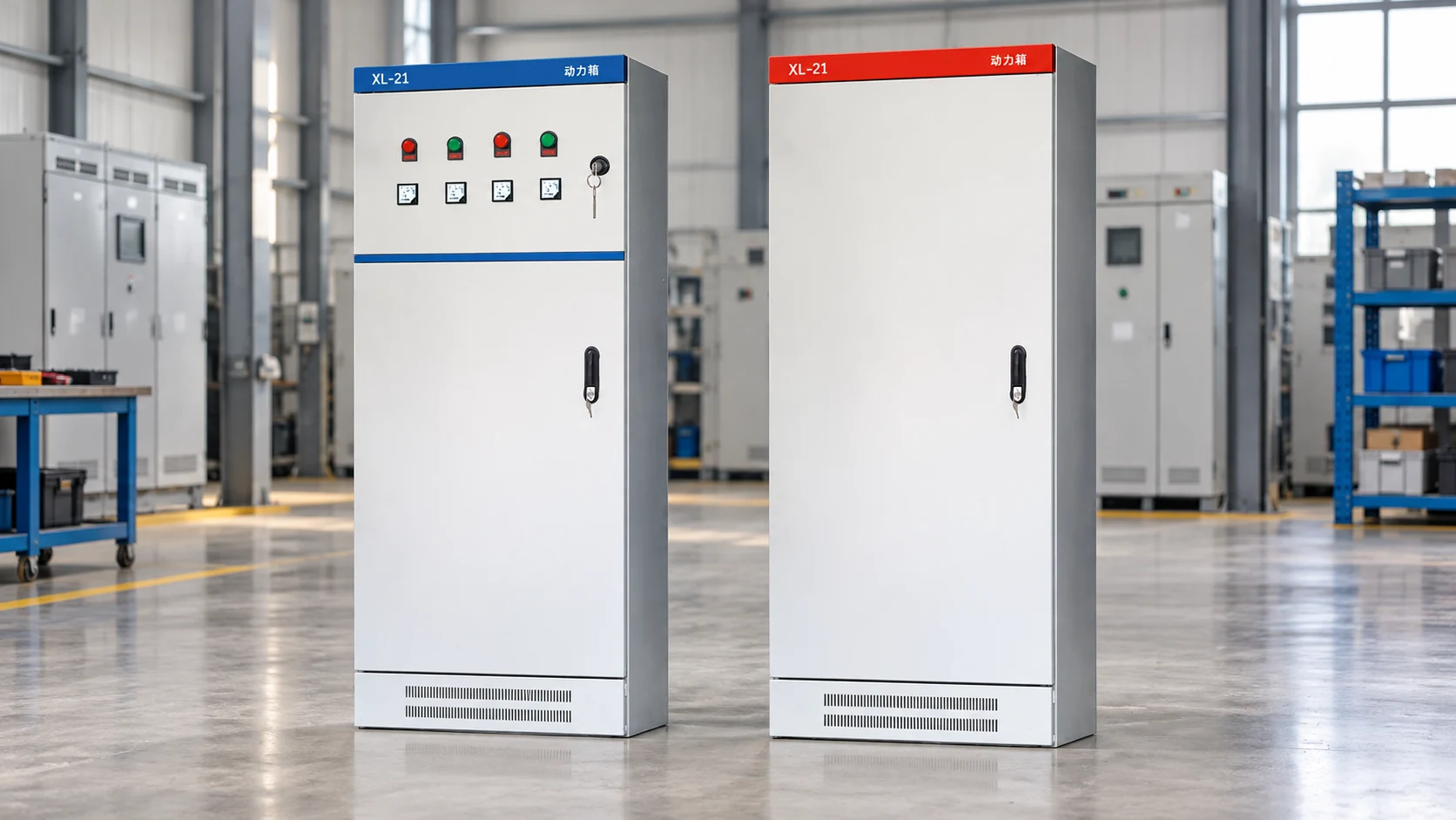
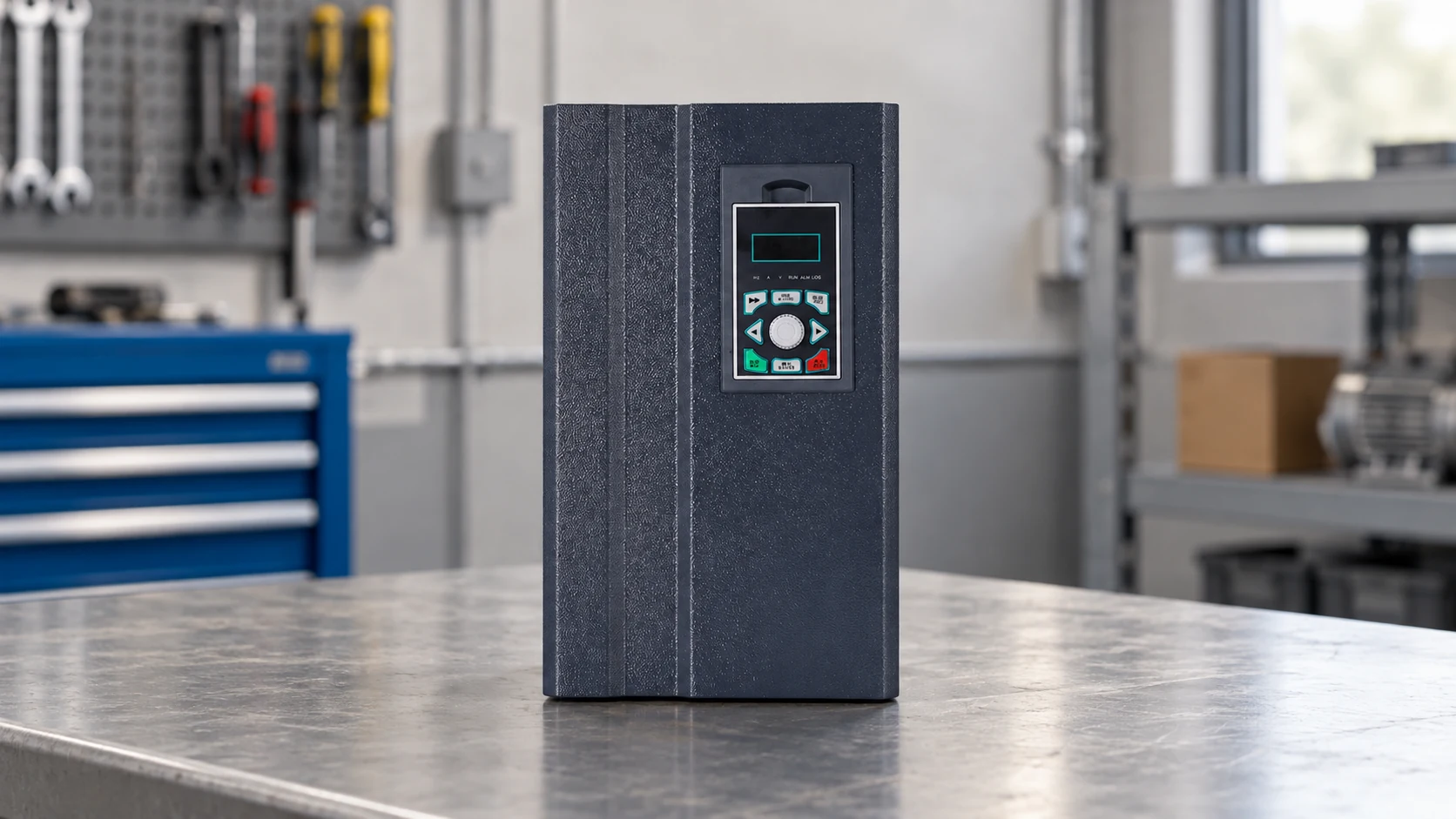
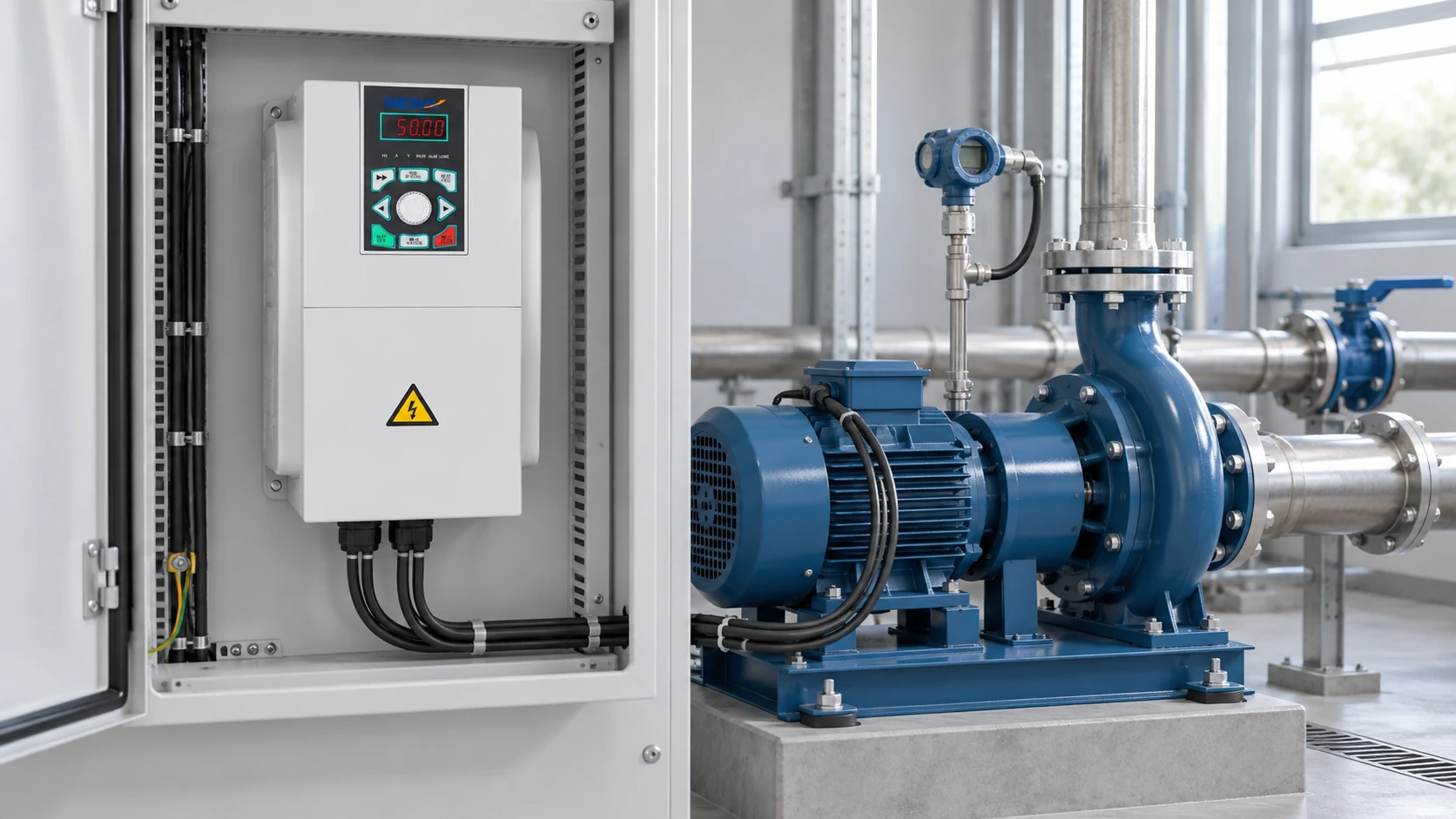
When an equipment buyer in Guangzhou encounters an 11 kW mixer that stalls during a reduced-voltage start, increasing the ramp time may seem like an easy fix. In this illustrative scenario, the loaded mixer needs more breakaway torque than the selected starting settings can deliver. A longer ramp does not create extra torque; it may extend the motor’s heating period. Selection must begin with the load and motor current.
Summary: An 11kW soft starter manages the starting voltage or current of a compatible motor, usually a three-phase induction motor. It does not provide continuous variable-speed operation. The 380 V selection example discussed below lists an 11 kW option at 22 A, but the actual motor nameplate and start duty must still be checked. There is no single starting-current reduction percentage valid for every 11 kW installation.
The starting method affects supply demand, acceleration torque and mechanical loading. The Department of Energy’s motor-system sourcebook recommends considering the complete system rather than a component in isolation. That approach is particularly useful when comparing a soft starter with direct-on-line starting, star-delta control or an 11kW VFD.
How an 11kW soft starter actually works
A conventional semiconductor soft starter controls the voltage applied during acceleration, using thyristors according to its design. It can raise the applied voltage progressively or regulate the starting current within its available control range. Supply frequency remains unchanged, so this is a starting method rather than a substitute for a variable frequency drive.
At a given operating condition, induction-motor torque is approximately proportional to the square of applied voltage. An illustrative reduction to 70% voltage therefore gives about 49% of the corresponding full-voltage torque: 0.7 × 0.7 = 0.49. This approximation helps explain why reducing starting stress also reduces the torque available to accelerate the machine. Actual torque varies with speed, motor design and load.
After acceleration, a built-in or external bypass contactor may carry the running current, depending on the product configuration. A bypass arrangement reduces losses in the semiconductor path during running. An online design and a bypass design must be assessed according to their own circuit and thermal requirements; their labels do not establish identical protection arrangements.
IEC 60947-4-2 covers semiconductor motor controllers, starters and soft-starters within its stated scope. A catalogue reference to this standard is not itself a certificate for a particular starter or a complete control panel. Obtain the exact model’s documentation when specifying acceptance requirements.
How much can it reduce starting current?
The answer depends on the motor, starting load, voltage, current limit and permitted acceleration time. Compare the actual measured direct-on-line starting current with the current required for a successful soft start. Reducing current below the level needed to overcome the load can prevent acceleration.
For illustration only, consider a motor with a 22 A nameplate. If its measured direct-on-line starting current were 6 times rated current, that would be 132 A. A successful start at 3 times rated current would be 66 A, or 50% below that illustrative baseline. Neither multiplier is a guaranteed setting for an 11kW soft starter. The result must be established with the actual motor and machine.
Starting current and thermal duty cannot be separated. A simple comparison at constant current gives 3² × 10 = 90 versus 3² × 30 = 270 in normalized current-squared-seconds. Tripling the duration triples this simplified heating indicator. Real thermal protection uses the product’s model and operating conditions, so this calculation must not replace the manufacturer’s start-duty curve.
Generator operation requires a wider assessment. Even if peak starting current falls, the generator still needs to support the running load, voltage response and other connected equipment. Do not promise that a smaller generator will work based on an assumed percentage reduction.
Size by voltage, current and start duty
Use the 11 kW motor power as an initial catalogue reference. Confirm supply voltage and motor rated current, then check starting time, starts per hour, ambient temperature, altitude and enclosure ventilation. A lightly loaded pump and a loaded mixer can require different selections despite matching power labels.
A power-based estimate can help identify missing information, but cannot replace a nameplate. For an illustrative 11 kW mechanical output, 400 V supply, efficiency of 0.90 and power factor of 0.85, the estimated current is 11,000 / (√3 × 400 × 0.90 × 0.85) ≈ 20.8 A. The assumed voltage, efficiency and power factor explain why this estimate differs from another motor or a 380 V catalogue entry.
| Item | Evidence to collect | Why it matters |
|---|---|---|
| Supply and motor connection | Actual line voltage, frequency, phase configuration and motor terminal diagram | Prevents an incorrect voltage or winding-connection assumption |
| Motor rated current | Nameplate photograph and required continuous duty | A power rating alone does not establish current compatibility |
| Starting load | Loaded/unloaded condition, breakaway torque and acceleration behavior | Reduced voltage must still provide enough accelerating torque |
| Start cycle | Start duration, starts per hour, cooling interval and hot restarts | Determines whether the starter’s thermal duty is adequate |
| Panel and protection | Ambient conditions, ventilation, bypass, protective-device selection and fault-level data | Defines the complete starter circuit and installation requirements |
The DOE sourcebook’s system approach also supports a useful commissioning record: note the starting condition, current, voltage behavior, time to full speed and any trips. If acceleration is unsuccessful, investigate load torque, motor connection and supply performance before repeatedly extending the ramp or resetting protection.
Compare an 11kW soft starter, VFD and star delta starter
The central question is whether the machine needs controlled starting or continuous speed adjustment. A fixed-speed load may benefit from a suitable soft starter. A process that changes output by changing motor speed requires a drive designed for that operating duty.
| Method | Running speed control | Starting behavior | Selection and ownership considerations |
|---|---|---|---|
| 11kW soft starter | No continuous frequency-based speed control | Adjustable voltage ramp/current control within the selected model’s limits | Check start duty, torque, bypass and coordinated protection |
| 11kW VFD | Yes, within the motor and machine limits | Controls frequency and voltage during acceleration | Check output current, overload, EMC, motor cooling and any braking needs |
| Star-delta starter | No | Reduced winding voltage in star, then transition to delta | Requires a compatible motor connection and sufficient starting torque |
| Direct-on-line starter | No | Applies full supply voltage at starting | Check supply capacity, mechanical stress and protection |
For a compatible star-delta arrangement, star starting gives approximately one-third of the direct-on-line delta starting torque and supply line current under comparable conditions. The motor must have the necessary accessible winding ends and be rated to run in delta at the available line voltage. Transition effects and insufficient torque can still make it unsuitable.
A soft starter does not normally reduce the energy required for a fixed-speed process after starting. A bypass path can reduce starter losses, but that is different from a VFD reducing motor speed when demand falls. Compare purchase cost, panel space, wiring, maintenance and production requirements rather than promising a universal payback.
Confirm model data, protection and installation requirements
NENA’s 5.5–22 kW built-in bypass soft starter listing publishes an 11 kW, 380 V selection-table entry of 22 A. Its small-frame technical indicators also state 300% current for 30 seconds. Treat these as published selection data requiring confirmation for the exact supplied model. They do not authorize every current-limit/ramp-time combination.
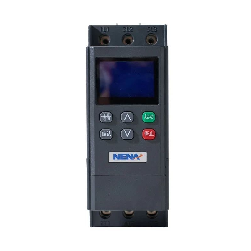
The same listing gives an adjustable current multiplier of 1–5 and a start-time adjustment range of 1–90 seconds. These are setting ranges, not a guarantee that the motor can start at every setting or that the starter can carry the maximum current for the maximum time. Review the overload limits and thermal recovery conditions together.
Specify the short-circuit protective device, overload function, isolation and bypass circuit as an assembly. A listed electronic protection feature does not by itself establish the fault rating of the whole panel. Discuss the applicable IEC 60947-4-2 requirements and, where relevant, the local control-panel or assembly requirements with the panel builder.
Qualified personnel should follow the exact wiring diagram and safe isolation procedure. Do not apply insulation-test voltage through connected control electronics. After commissioning, retain settings and test records so a later replacement can be assessed against actual operating duty.
Prepare an 11 kW motor starting enquiry
For a NENA quotation, supply the motor nameplate, supply details, load description, start duration, starts per hour and installation conditions. State whether full-speed running is sufficient or whether the process needs adjustable speed. The 5.5–11 kW general-purpose inverter listing provides a related option for applications requiring speed control.
If comparing starting methods, the three-phase soft starter selection guide provides additional context. Agree on a successful loaded start, acceptable supply response and documented protection settings as acceptance conditions, rather than specifying only a reduction percentage.
Frequently Asked Questions
How does an 11kW soft starter actually work?
It controls applied motor voltage or starting current during acceleration using semiconductor switching. A bypass arrangement may then carry the running current, depending on the design. It operates at the supply frequency and does not provide the same continuous speed adjustment as a VFD.
How much does it reduce the motor’s starting current?
There is no universal percentage. The achievable reduction depends on the motor’s direct-on-line current, load torque, current limit and acceleration time. Verify the result during a successful start without exceeding the motor or starter thermal limits.
What exactly is an 11kW soft starter?
It is a soft starter offered for an approximately 11 kW motor application under specified voltage and duty conditions. The rating is conditional: NENA’s published 380 V table pairs 11 kW with 22 A. Confirm the actual motor current and operating cycle before treating that catalogue entry as suitable.
Why is it needed for an 11kW motor?
It may be useful when full-voltage starting creates unacceptable supply demand or mechanical stress. An 11 kW motor does not automatically need a soft starter; a properly engineered direct-on-line or other starting method may be adequate. Select against the supply and machine requirements.
Should I choose an 11kW VFD instead?
Choose a suitable VFD when the process needs adjustable running speed or other drive functions. Choose a soft starter when controlled starting followed by fixed-speed operation meets the requirement. Current capacity, load duty and installation requirements still need checking for either option.
References
- U.S. Department of Energy: Improving Motor and Drive System Performance.
- U.S. Department of Energy: Motor Systems technical publications and assessment resources.
- IEC catalogue: IEC 60947-4-2 for semiconductor motor controllers, starters and soft-starters.
A suitable starter must reduce starting stress while still accelerating the load. Contact NENA with your motor and application data to confirm an 11kW soft starter selection.