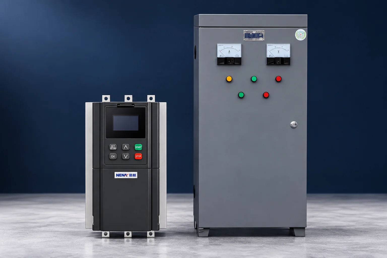
VFD overvoltage during deceleration often occurs when the slowing motor returns energy to the drive faster than the system can absorb or dispose of it. The DC bus voltage rises and the drive trips at its protective limit. However, an excessive incoming supply voltage, a supply disturbance or a fault in an installed braking circuit can produce a similar indication. Preserve the exact fault record, identify when the voltage rise occurs and compare the actual stop with the machine’s requirement before changing parameters.
This guide explains the diagnostic sequence for industrial motor-drive systems. It does not provide universal trip thresholds, resistor values or instructions for accessing an energized DC bus. The model-specific manual and the machine’s approved stopping design govern the work.
Confirm that the code means DC bus overvoltage on the exact drive model. Similar letters can represent different faults across brands and product families. Record the full code, timestamp, operating state, speed reference, load condition, recent settings changes and any available drive-monitor values. A photograph of the display can be useful, but preserve the event history as well.
A fault that appears consistently after a stop command suggests a different investigation from one that occurs before the motor runs. Also distinguish controlled ramp stopping from coasting, reversal and a safety-related stop sequence. A PLC or machine controller may select an alternate deceleration time that differs from the value visible in the normal operator menu.
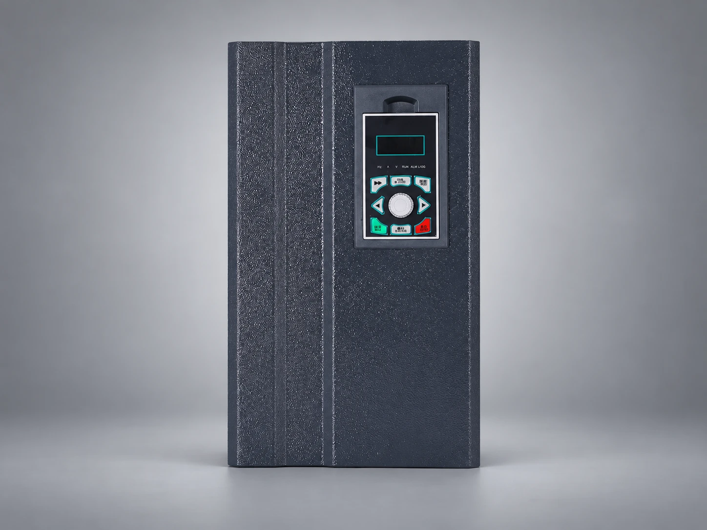
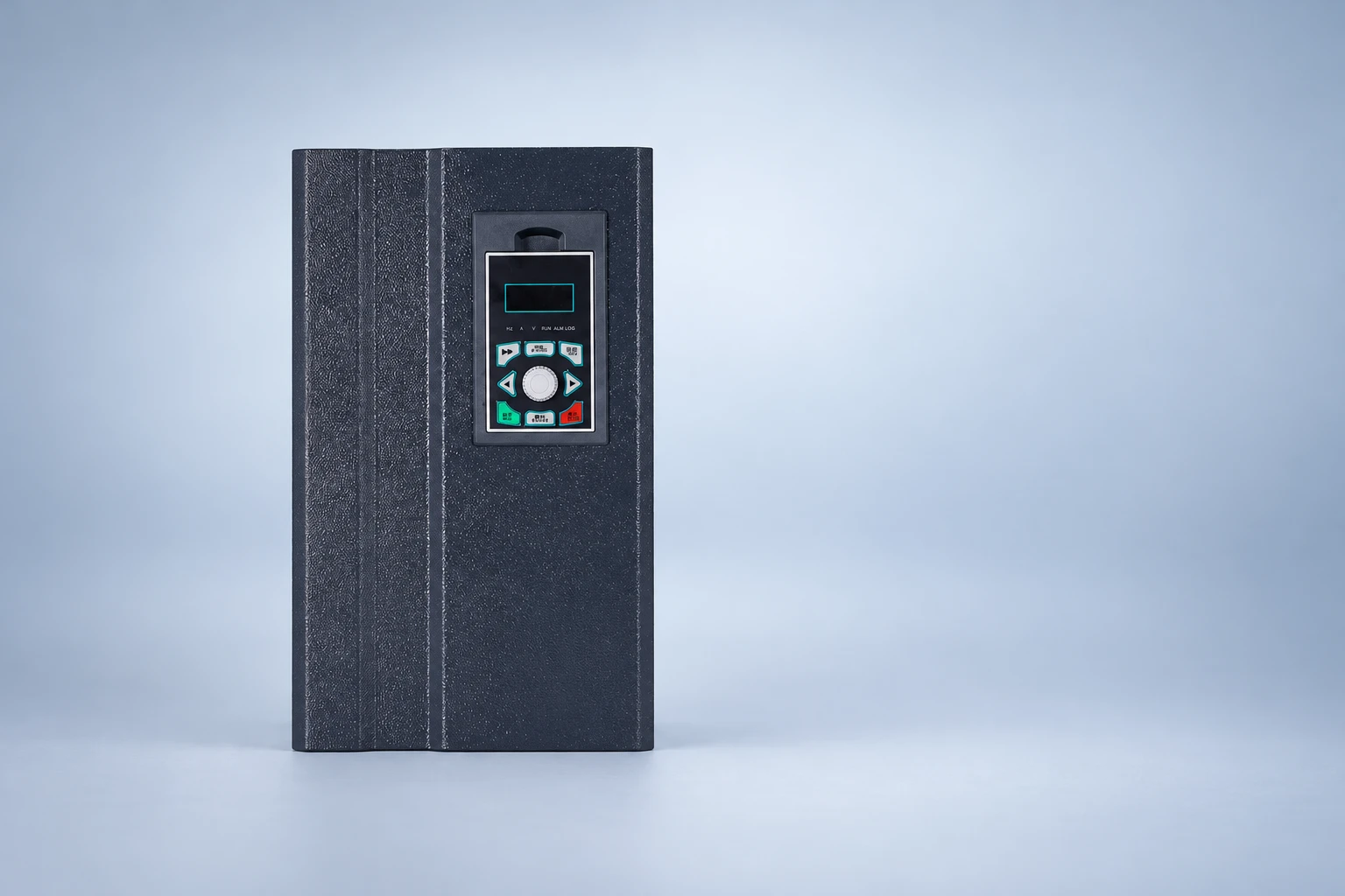
For the underlying conversion stages, see our VFD operating-principle guide. The front-panel illustration below identifies a NENA current-vector inverter product reference; it does not depict an overvoltage code or claim that a particular fault is present.
During electrical braking, the motor can operate as a generator while mechanical energy is removed from the load. That energy must go somewhere. Depending on the drive and system, it may be handled through losses, a compatible braking circuit, an energy-return arrangement or other approved equipment. Many ordinary diode-input VFDs cannot simply send regenerative energy back to the AC supply.
The DC-link capacitors can store only a finite additional amount of energy between their normal operating voltage and a higher voltage. A braking chopper and resistor, where supported and properly selected, convert returned energy into heat. A regenerative supply arrangement is a different solution. OpenStax’s explanation of capacitor energy gives the relationship E = ½CV², which explains finite energy storage as voltage rises. This physics relationship does not determine a drive’s permitted bus voltage or replace its braking-equipment selection rules.
A high-inertia fan or flywheel can contain substantial stored energy even when the motor’s normal current is modest. A descending or otherwise overhauling load may continue feeding mechanical energy during motion. For that duty, a longer deceleration time alone may not resolve the energy-management requirement.
For a rotating system with constant equivalent inertia J, the reduction in kinetic energy is ΔE = ½J(ω1² − ω2²). J is in kg·m², angular speed ω is in rad/s, and energy is in joules. Convert RPM using ω = 2πn/60. OpenStax’s university physics treatment of rotational kinetic energy gives the physical basis.
As a hypothetical example, take J = 2 kg·m² and a stop from 1,500 RPM to rest. The energy reduction is approximately 24.7 kJ. Removing that mechanical energy over 5 seconds corresponds to about 4.9 kW average power over the stop; spreading it over 20 seconds corresponds to about 1.2 kW. These figures are illustrative energy-budget calculations, not resistor ratings.
Friction and process work can absorb part of the energy, while an externally driven load can add energy. Transmission ratio changes the inertia referred to the motor shaft. Actual peak braking power, allowable torque, electrical losses, repeat cycle and component thermal behavior also matter. Use the estimate to reveal the duty, then obtain a complete manufacturer-approved selection.
A longer stop reduces the average power associated with a fixed energy change, but it does not eliminate the energy itself. The machine may also require a specific stopping distance or time. That is why a parameter change that prevents a trip is not automatically an acceptable production or safety solution.
| When the fault appears | Questions to investigate | Evidence to retain |
|---|---|---|
| Before running or while idle | Is the supply within the drive’s documented range? Are there supply disturbances or a sensing issue? | Incoming supply record, drive voltage class and event history |
| Only during a rapid ramp stop | Does returned energy exceed the available braking path? | Selected stop mode, actual speed reduction and drive bus trend |
| While lowering or being driven by the process | Is the load continuously regenerating or overhauling? | Motion direction, mechanical duty and power-flow description |
| After a brake-circuit repair or change | Are the specified components, protection and settings correct? | Approved circuit, exact component identifiers and maintenance record |
| After repeated stops | Is a thermal limit or interrupted braking path affecting repeated-duty capability? | Cycle timing, temperatures, protective-device state and fault history |
The table prioritizes investigation; it does not prove a cause from one observation. Check whether the fault follows a higher incoming supply voltage, a greater starting speed, a changed load or a shorter machine-controller stop command. Compare equivalent operating conditions rather than concluding that the drive has failed because a different day produced a different result.
Use the drive’s documented monitoring functions where available. Accessing internal power terminals is a separate electrical task requiring appropriate personnel, procedures and instrumentation. Do not connect an ordinary meter or oscilloscope to an energized DC bus as an informal troubleshooting shortcut.
If the process permits a longer controlled stop, the responsible engineer can review an increase within the supported range and validate the resulting motion. First identify the active ramp selection, reference units and stop mode. Some drives define ramp time relative to a base frequency, so the entered number may not equal the measured time from the present speed to zero.
Some products provide bus-voltage control that can extend the effective deceleration when regenerative energy raises the bus. Confirm the actual feature and its interaction with installed braking equipment in the exact manual. Do not infer that every drive offers the same function or copy another brand’s enable/disable recommendation.
Do not raise a protective threshold, suppress the fault or repeatedly reset a reproducible overvoltage trip to force the requested stop. A drive trip may also change the stopping behavior, making the situation a machine-level concern. Changes to a normal operating stop must be reviewed separately from any emergency-stop or suspended-load requirements.
A resistor alone does not establish a working braking path. Confirm whether the drive supports an internal braking chopper, requires an external unit or uses a different energy-return arrangement. Identify the approved resistor resistance, pulse-energy capacity, continuous and intermittent duty, thermal protection, enclosure location and wiring arrangement.
Too low a resistance can overload the switching equipment; too high a resistance may provide insufficient braking power. Neither direction is a universal fix. A higher wattage printed on a resistor also does not prove that its resistance, pulse duty and protection suit the drive. Use the exact unit’s selection rules and the actual stopping cycle.
Qualified personnel should inspect a suspected open connection, failed resistor or protective-device operation only under the applicable isolation procedure. Braking resistors can remain hot, and drive capacitors may retain hazardous energy. CCOHS’s lockout and tagout guidance explains why operating controls are not energy-isolating devices and why stored energy needs attention. Follow the equipment-specific discharge and verification instructions.
Agree on the acceptance conditions: starting speed, actual load, stop command, required stopping time or distance, normal repeat interval and worst permitted consecutive stops. Record actual motion, fault history, available bus-voltage information and braking-component thermal evidence. A single unloaded stop does not establish repeated production performance.
Consider what changed before the problem began. A larger fan impeller, altered gearbox, increased maximum speed, changed product loading or shorter PLC timer can change stopping demand without changing the motor kW label. A supply change can reduce voltage headroom as well. The corrective action should address the changed requirement rather than hide it in an undocumented parameter.
If the review identifies sustained regeneration or a strict rapid-stop requirement, the solution may need a different braking or regenerative arrangement. Do not assume that replacing the drive with a larger unit alone will provide that functionality. Our motor inverter selection guide explains the wider specification process.
Provide the exact drive and motor nameplates, supply information, complete fault code, operating history, speed before stopping, selected and measured deceleration times, load and inertia information, stop repetition and any installed braking hardware. Include the machine’s acceptable stopping behavior and recent controller or mechanical changes.
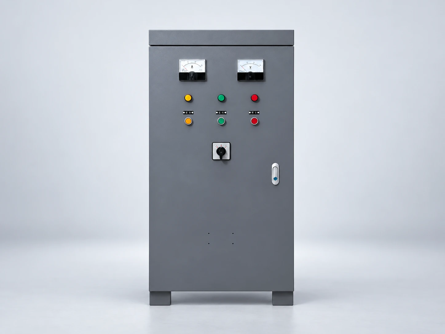
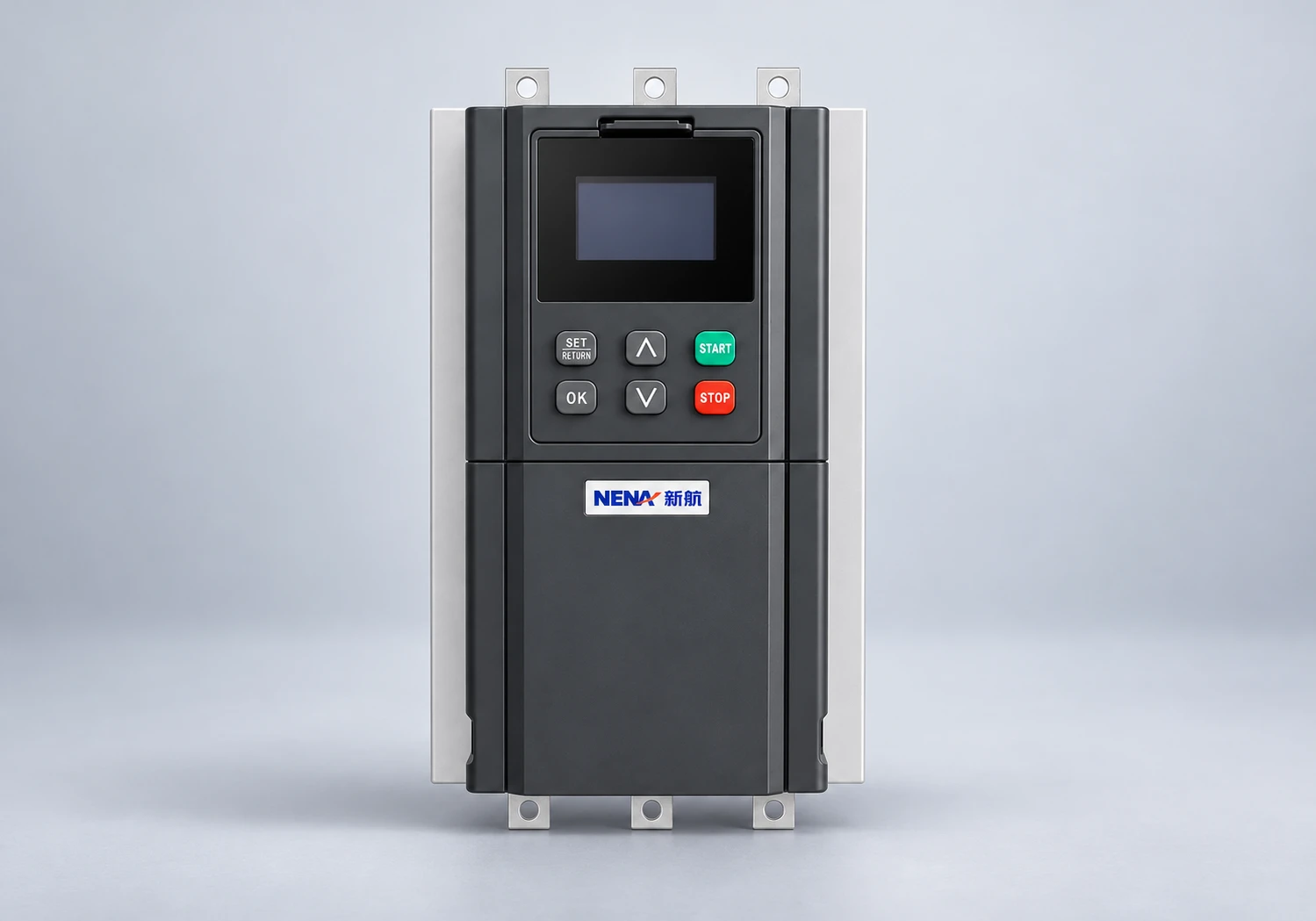
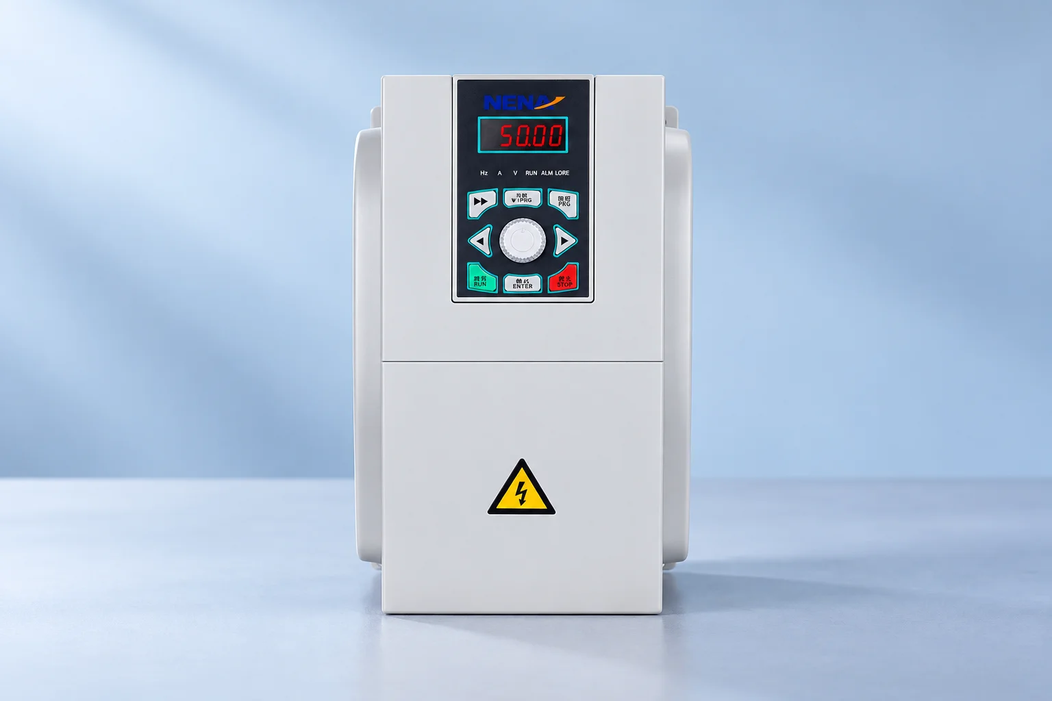
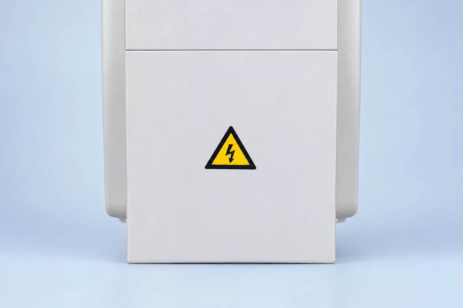
The NENA general-purpose inverter is the light-gray product reference used in the illustrations. The additional current-vector inverter reference identifies a different NENA product; the two photos do not establish interchangeable ratings. Confirm the braking options and limits of the exact supplied model; the photograph and this article do not establish an integrated chopper or a permitted resistor value. If noise and thermal settings are also being changed, our carrier-frequency guide addresses that separate parameter trade-off.
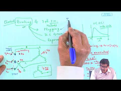
This NPTEL IIT Kharagpur lecture explains electrical braking principles. It provides independent background, not a fault-code or wiring tutorial for a particular NENA drive.
Watch on YouTube — NPTEL IIT Kharagpur
No. Regenerative energy during deceleration can raise the DC bus even when the incoming supply is normal. Supply voltage and disturbances still need to be checked against the actual fault timing.
Only where the resulting stop is acceptable and the system can handle the energy and duty. Sustained overhauling loads or strict stopping requirements may need a different braking arrangement.
No. The drive must support a compatible braking arrangement. Resistance, energy duty, protection and installation must follow the exact drive or braking-unit documentation.
No. More motor-driving capacity does not automatically add the required braking path, regenerative capability or stopping performance. Specify the full motion and energy duty.