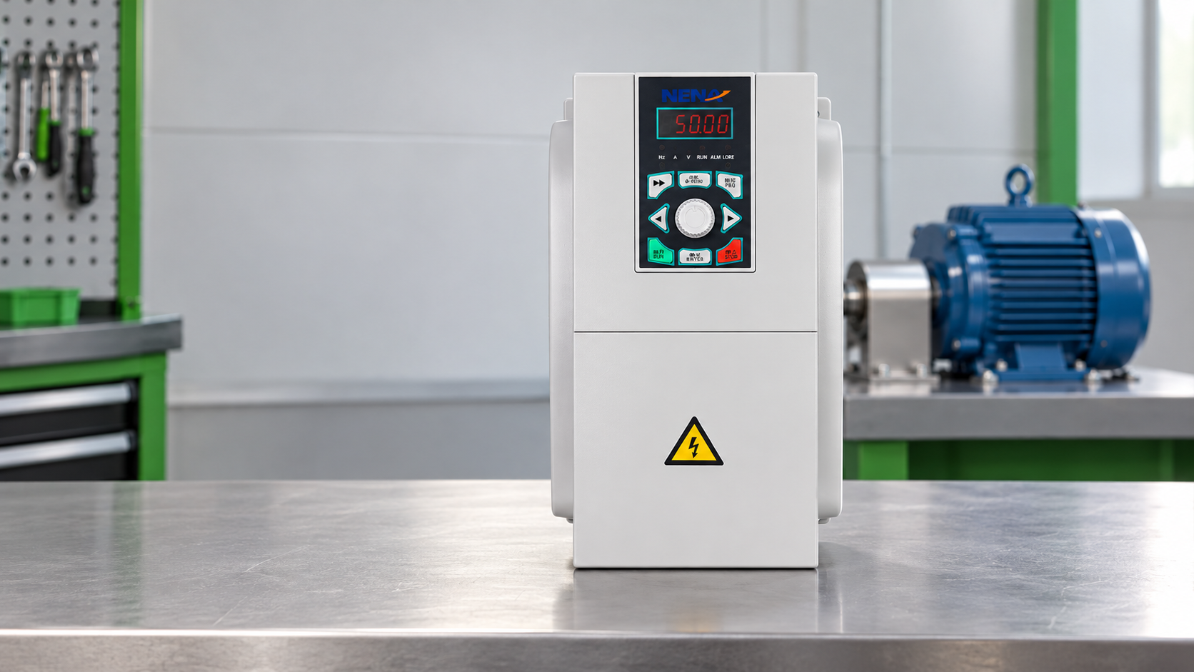
When Elena Ruiz, a maintenance engineer in Monterrey, encountered a conveyor that stalled whenever a heavy carton entered the line, she increased the controller setting and restarted the motor. The line accelerated, tripped on overcurrent within seconds, and left the motor hotter than before. A review of the nameplate, load profile, and cable run showed the real problem: the controller had been selected for rated horsepower alone, while the conveyor needed controlled torque at low speed and a duty-rated overload profile. Correct selection restored predictable acceleration without replacing the motor.
Summary: A controller for a three-phase motor should be selected from the motor nameplate, load torque curve, starting frequency, ambient conditions, braking needs, and applicable safety and EMC requirements—not from kW alone. A variable-frequency drive normally changes speed by changing frequency and voltage, while a soft starter primarily manages acceleration and does not provide continuous speed regulation. Confirm the motor’s rated current, duty, enclosure, and installation method against IEC 60034-1 and the applicable IEC 61800 requirements before ordering.
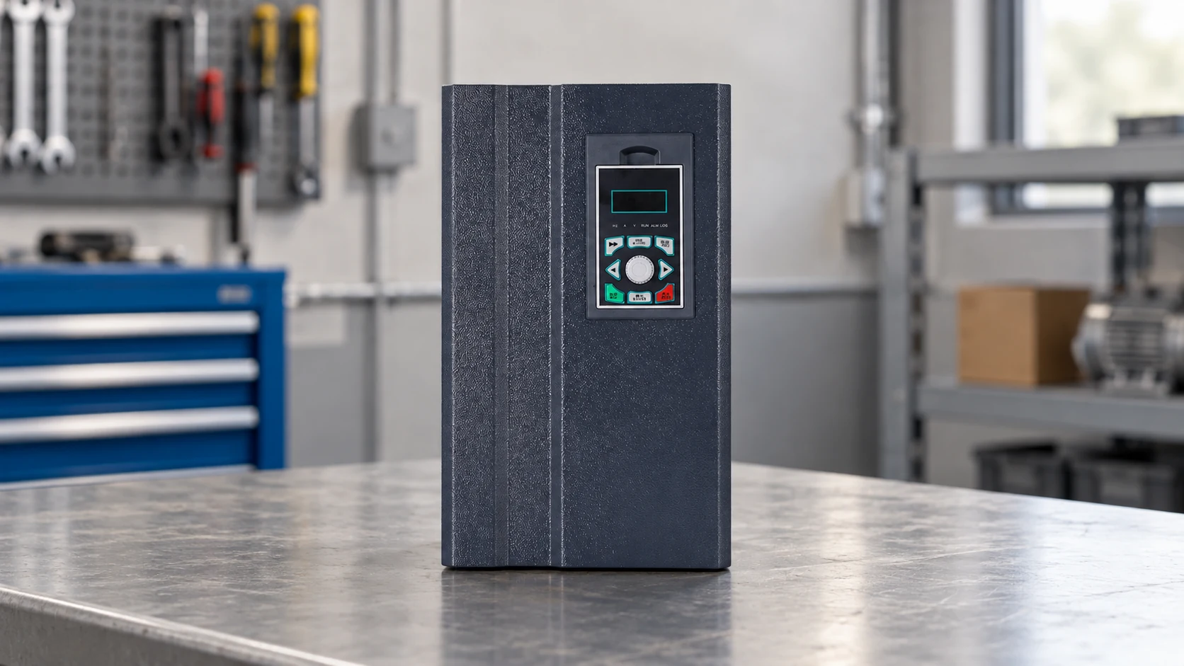
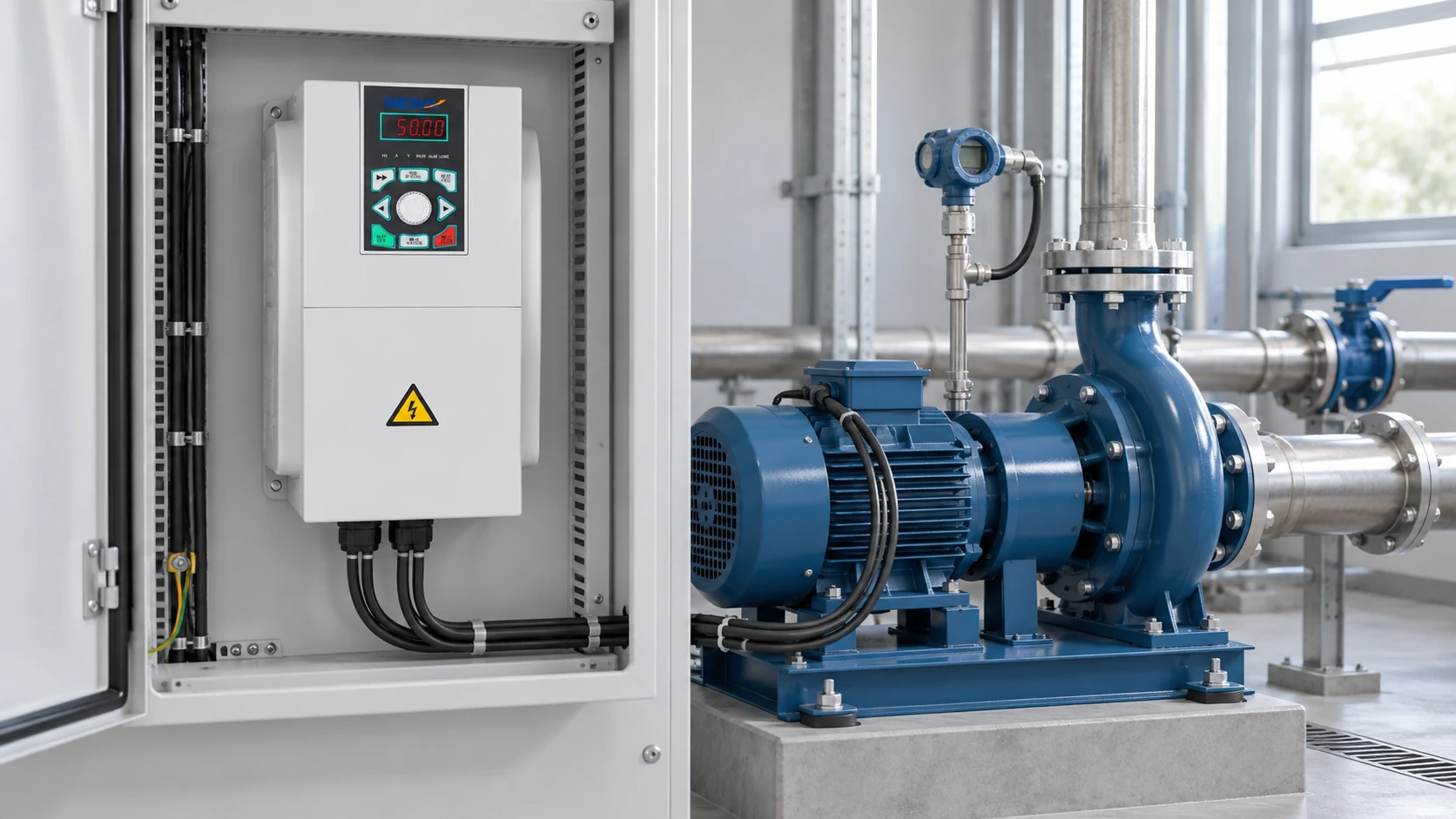
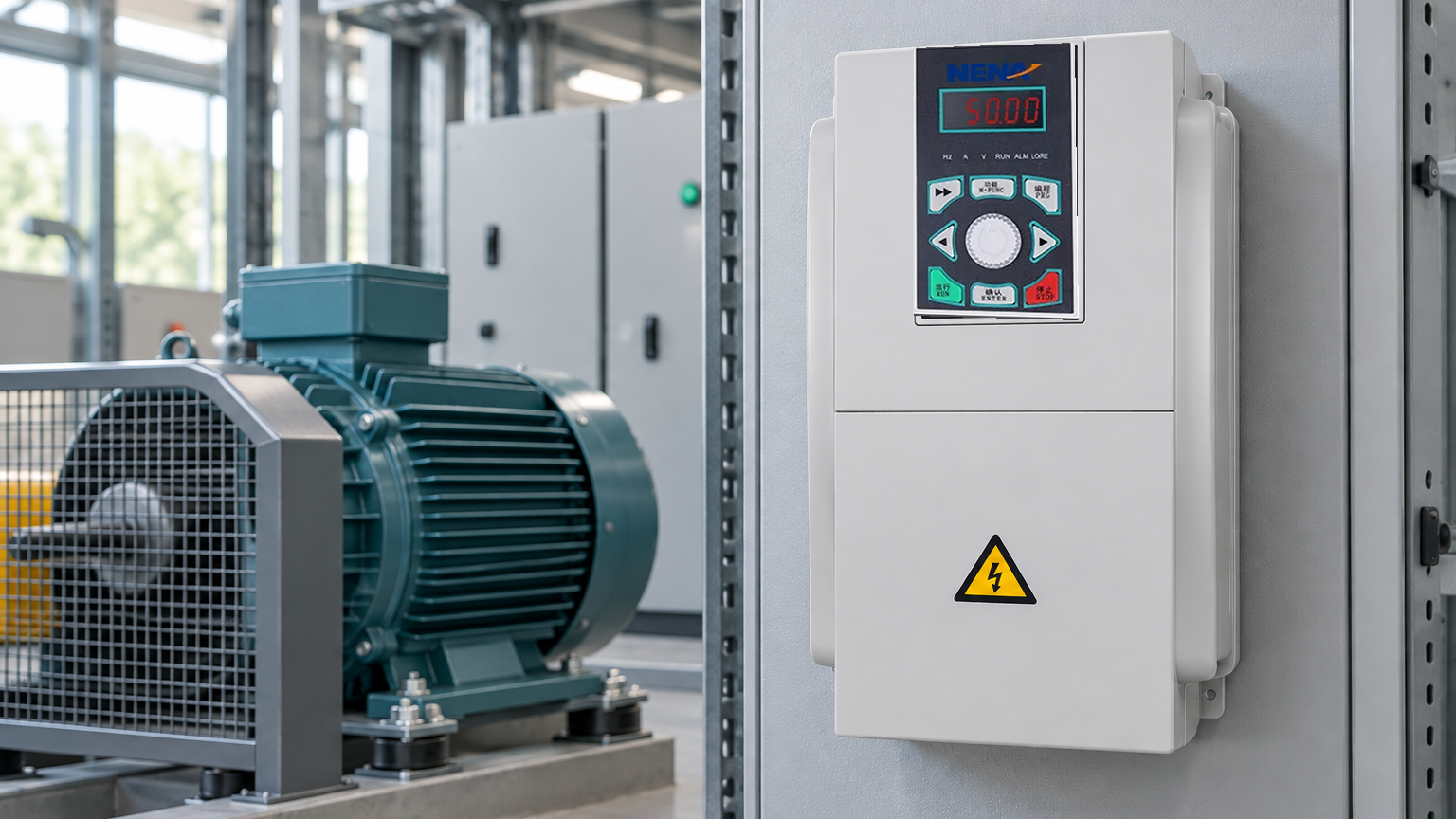
The phrase “speed controller” covers several power-electronic architectures. A variable-frequency drive (VFD), also called an adjustable-speed drive, rectifies incoming AC, creates a DC link, and synthesizes a variable-frequency output with insulated-gate bipolar transistors or a comparable switching stage. With an induction motor, changing output frequency changes synchronous speed; maintaining an appropriate volts-per-hertz relationship helps preserve magnetic flux below base speed. Sensorless vector or closed-loop control can improve low-speed torque when the application requires it.
In contrast, a soft starter uses controlled thyristor firing to ramp the applied voltage during starting and stopping. It can reduce inrush and mechanical shock, but it does not normally maintain a commanded running speed. A bypass contactor may carry current after acceleration, reducing heat in the semiconductor path; bypass selection must still account for duty, fault coordination, and permissible starts per hour. XINHANG’s online soft starter for motor starting is a relevant comparison when the process needs a gentler start rather than variable running speed.
Motor speed follows the approximate relationship:
n_s = 120f / p
where n_s is synchronous speed in revolutions per minute, f is electrical frequency in hertz, and p is the number of motor poles. Actual induction-motor speed is lower because of slip. A drive therefore changes speed by controlling frequency and slip, not by simply lowering voltage. Voltage-only control can produce overheating, poor torque, or unstable operation when used outside the motor’s intended design.
For the selected 3 phase motor speed controller, verify at least these values:
The motor nameplate and IEC 60034-1 ratings establish the starting point; the application profile determines the drive class. For pumps and fans, torque commonly rises approximately with the square of speed and power with the cube of speed, so reducing speed can materially reduce energy demand. Conveyors, mixers, hoists, and extruders can require near-constant torque and higher low-speed thermal consideration.
A frequency inverter is usually the better fit when the process needs repeatable speed commands, controlled acceleration over a wide range, energy reduction from throttling losses, or coordinated operation between multiple motors. A pump that formerly used a valve to throttle flow may reduce valve loss when the drive adjusts speed, but the saving depends on the actual system curve, operating hours, minimum-flow constraints, and motor efficiency. Treat any payback figure as an application calculation, not a guaranteed result.
Use a soft starter instead when the motor normally runs at full speed and the primary problems are inrush current, voltage dip, water hammer, belt shock, or mechanical stress during starting. A soft starter may have a lower control complexity and lower conversion loss during bypass operation, while a VFD adds speed functionality, harmonic and EMC considerations, and more settings to commission. The right answer follows process behavior rather than a generic preference for one technology.
The selection also depends on braking and regeneration. A high-inertia fan may coast safely, whereas a hoist, centrifuge, or fast-indexing machine may need a braking resistor, regenerative unit, mechanical brake interface, or a controlled stop category. Confirm the stopping energy and duty cycle with the drive manufacturer. Do not size a braking resistor from motor kW alone; calculate inertia, speed, stopping time, repetition, and resistor thermal capacity.
| Dimension | VFD / frequency inverter | Online soft starter | Bypass soft starter | Direct-on-line starter |
|---|---|---|---|---|
| Primary function | Continuous speed and torque control | Controlled start/stop with semiconductor path in service | Controlled start/stop, then contactor bypass | Full-voltage starting |
| Low-speed operation | Available when motor and drive are rated for it | Not normally regulated | Not normally regulated after bypass | Not available |
| Starting current | Programmable and generally lower than direct-on-line | Limited by ramp and current settings | Limited during ramp; bypass after start | Highest of the four in many applications |
| Energy opportunity | Can reduce flow-related losses at reduced speed | Little running-speed saving | Little running-speed saving | None from speed control |
| Harmonic and EMC work | Requires drive, cable, filter, and earthing review | Still requires power-quality review, usually less switching complexity | Same, with bypass coordination | Simpler power path but high starting demand |
| Best fit | Pumps, fans, conveyors, mixers, process lines | Pumps, compressors, conveyors, and motors that run full speed | High-current full-speed motors where bypass is useful | Small or lightly constrained motors |
| Maintenance focus | Cooling, DC-link condition, settings, cables, bearings | Thyristors, cooling, bypass contactor, settings | Thyristors, bypass contactor, coordination | Contactor, overload relay, and mechanical connections |
| Total-cost drivers | Drive, installation, EMC, commissioning, and energy profile | Starter, bypass, coordination, and mechanical benefits | Starter, bypass, cabinet space, and serviceability | Larger supply infrastructure and mechanical stress |
Start with current, not only horsepower. A controller’s continuous output current should meet or exceed the motor’s actual full-load current for the selected voltage and duty. If the load has high breakaway torque, frequent starts, low-speed operation, or shock loading, use the manufacturer’s heavy-duty or constant-torque rating and check its overload duration. A 30 kW motor can present very different drive requirements as a centrifugal fan, a loaded conveyor, or a hoist.
Check the following sequence before procurement:
The motor’s thermal behavior is often the hidden constraint. At low speed, a standard self-cooled motor can move less air even though shaft torque remains high. An independent blower, reduced torque, a motor with inverter-duty insulation, or a minimum-speed limit may be necessary. A drive’s overload rating does not automatically make the motor safe during extended low-speed operation.
Cable length and switching edges can create reflected-wave stress at the motor terminals. Long runs may require an output reactor or a dV/dt or sine-wave filter, subject to the drive and motor supplier’s instructions. Keep control and motor power cables separated, bond the shield or armor correctly, and avoid routing encoder or analog signals alongside high-frequency output conductors.
| Application or constraint | Required performance emphasis | Sizing and specification checks | Cost or risk driver |
|---|---|---|---|
| Centrifugal pump or fan | Variable torque, stable minimum flow, sleep or wake control | System curve, minimum speed, bypass needs, wet-well or fan constraints | Oversizing, poor setpoints, and operation away from the efficient region |
| Conveyor or mixer | Constant torque, breakaway torque, controlled acceleration | Heavy-duty current, overload time, gearbox ratio, jam response | Undersized current rating and belt or coupling shock |
| Hoist or vertical axis | Controlled stop, holding brake interface, regenerative energy | Brake sequencing, resistor or regeneration, safe torque-off design | Dropped-load risk, braking heat, and inadequate fault response |
| Compressor | Torque profile, restart behavior, pressure control | Motor cooling, minimum speed, restart inhibit, process relief | Short cycling, pressure instability, and unplanned downtime |
| Long motor cable or sensitive facility | EMC, reflected-wave mitigation, low leakage | Cable construction, filters, earthing, RCD compatibility | Nuisance trips, bearing currents, and radio interference |
| Hot, dusty, or high-altitude site | Thermal margin and enclosure protection | Derating curve, cooling path, IP/NEMA enclosure, service access | Premature component aging and blocked airflow |
An illustrative total-cost calculation should include the controller, cabinet, line and load-side components, engineering, commissioning, training, expected energy impact, downtime avoided, and spares. For example, a pump that runs many hours at partial flow may justify a VFD through reduced throttling losses, while a rarely started motor may not. Use measured load and operating-hour data before claiming a payback period.
Installation begins with a documented single-line diagram and a lockout/tagout procedure. A DC link can remain energized after the incoming disconnect opens; wait the period specified by the manufacturer and verify absence of voltage with a suitable test instrument before opening the enclosure. The applicable safety framework includes IEC 61800-5-1 for adjustable-speed power drive system hazards and local electrical rules for enclosure, protective bonding, isolation, and work practices.
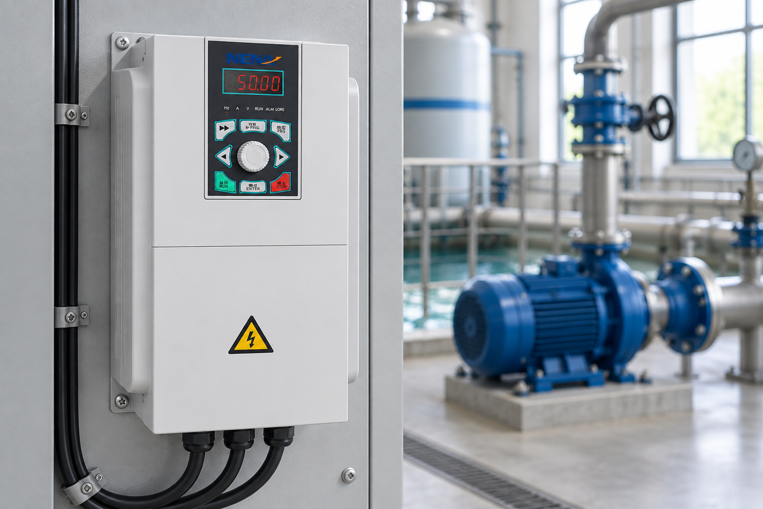
EMC performance depends on the complete installation. IEC 61800-3 addresses EMC requirements and test methods for power drive systems; its limits and environment categories should be matched to the intended industrial or residential setting. Follow the drive maker’s cable length, shield termination, filter, carrier-frequency, and leakage-current guidance. A compliant drive can still produce an unacceptable installation if bonding or cable routing is poor.
Harmonics are a separate power-quality question. A six-pulse rectifier can draw non-sinusoidal current; the impact depends on drive population, transformer impedance, background distortion, and the utility or facility limit. Where a project invokes IEEE 519 or a local utility requirement, measure or model the point of common coupling and consider line reactors, passive or active filters, a multi-pulse front end, or an active front end. Do not present a harmonic number from a product data sheet as proof of site compliance.
Before energizing, verify phase sequence where applicable, protective earth continuity, insulation and motor-cable condition, control polarity, emergency-stop behavior, safe torque off (if used), motor rotation with the load uncoupled, and the minimum and maximum speed limits. Record parameter backups and as-left measurements. A commissioning sheet should identify firmware, motor data, fault history, protection settings, and who approved any bypass or override.
Use a short procurement specification that makes the operating envelope explicit:
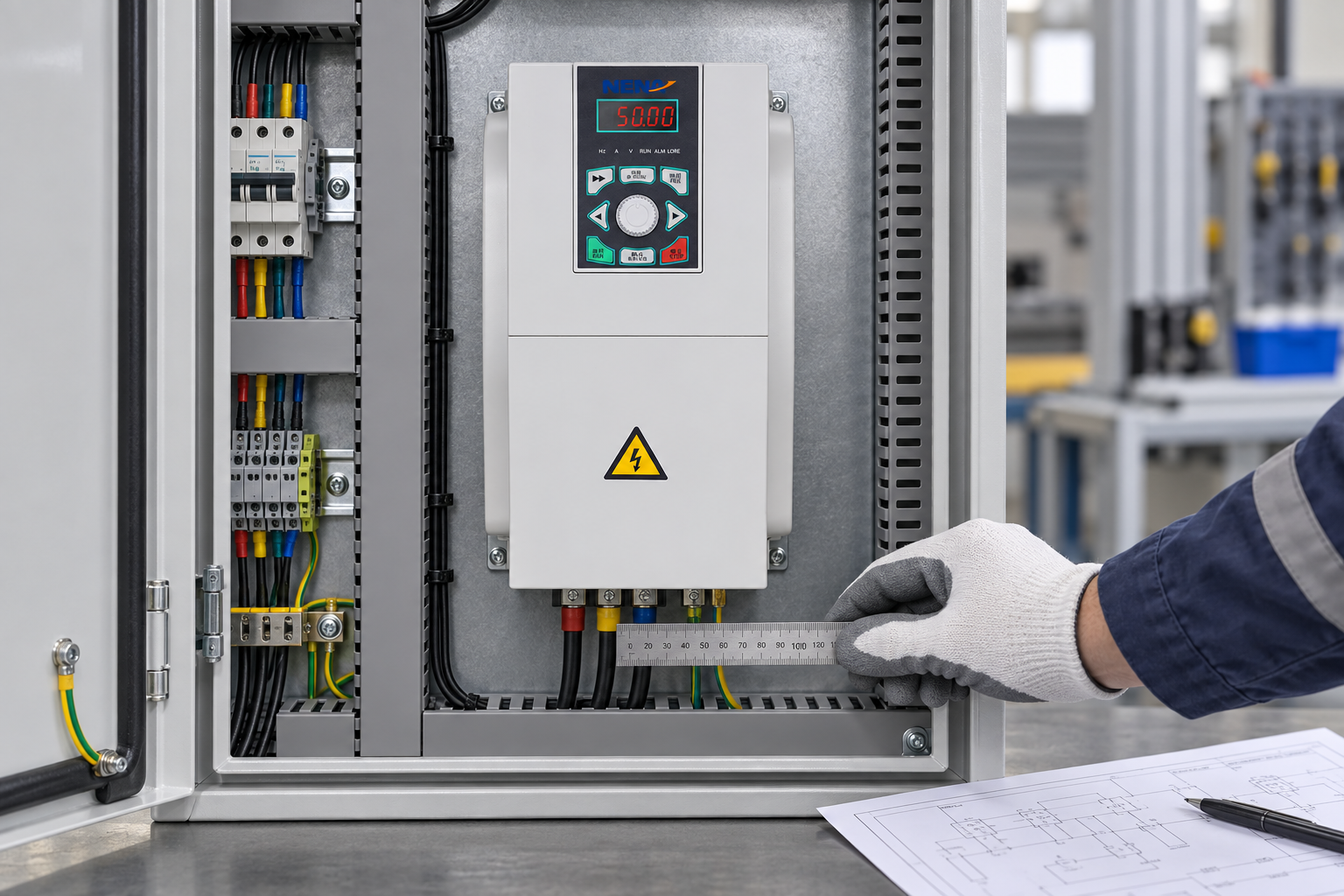
Ask for a dimensional drawing, terminal schedule, derating curve, wiring diagram, fault-code list, test record, spare-parts recommendation, and commissioning procedure. If a cabinet is supplied, verify heat dissipation, clearances, cable-entry method, busbar or terminal ratings, and whether the stated enclosure rating applies after field modifications. The commercial quote should identify what is included in factory testing and what remains a site responsibility.
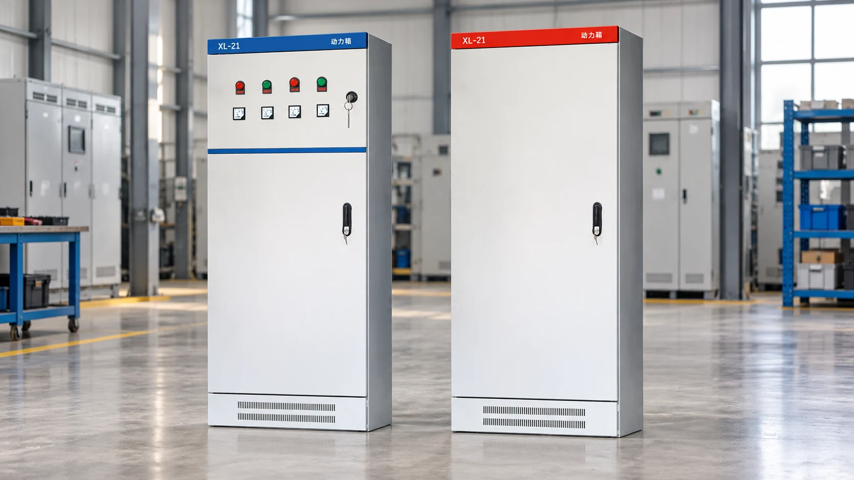
XINHANG can be considered when a project needs configurable motor-starting equipment, panel documentation, or a comparison between online and bypass architectures. For a full-speed motor that benefits from reduced starting stress rather than continuous speed variation, compare the bypass soft starter option against the electrical and mechanical requirements. The product choice should follow the approved specification and test evidence; brand selection comes after the duty and compliance envelope is clear.
| Standard or rule | Scope in this decision | Commercial consequence |
|---|---|---|
| IEC 60034-1 | Rating and performance fundamentals for rotating electrical machines | Motor data and test conditions must be interpreted consistently; it is not a blanket approval of a complete drive system |
| IEC 61800-5-1 | Safety requirements for adjustable-speed electrical power drive systems | Supports hazard review for the drive system; installation and local code duties remain |
| IEC 61800-3 | EMC requirements and test methods for power drive systems | Product test results do not replace site-level cable, bonding, filter, and environment verification |
| NEMA MG 1 | U.S. motor and generator construction, performance, and application guidance | Useful for motor/drive compatibility and application language; check the specific part and edition |
| IEEE 519 or local utility rule | Harmonic control at the point of common coupling where adopted | Limits may apply to the facility or installation, not simply to an individual controller |
| Local electrical and workplace rules | Isolation, protective devices, guarding, wiring, and work practices | Destination-market compliance, inspection, and liability depend on the installed system and claims made |
These standards are not interchangeable product badges. A test method describes how performance is evaluated; a product certification or declaration has a distinct scope and issuing basis. Request the exact certificate, declaration, or test report and confirm its model, options, ratings, edition, and destination-market applicability. Unsupported claims can delay acceptance, invalidate a specification, or create warranty and liability disputes.
The correct controller is the one whose current, overload, control range, braking, enclosure, EMC, and protection ratings match the motor and its load. Choose a VFD when continuous speed control is required; choose a soft starter when the motor normally runs at full speed and the goal is a smoother start or stop. Confirm the nameplate and load profile before selecting by kW alone.
A VFD rectifies AC to a DC link and switches that energy into a controlled three-phase waveform with a selected frequency and voltage. Motor speed changes with frequency, while the control algorithm manages flux, torque, acceleration, and protection. A soft starter instead controls the applied voltage during starting and normally bypasses or remains in the power path after the ramp, so it is not a substitute for continuous speed regulation.
No, not as a general solution for an industrial three-phase motor. Household dimmers are designed for compatible single-phase loads and may create severe waveform distortion, overheating, loss of torque, or unsafe failure when connected to a motor. Use a controller rated for the motor’s phase, voltage, current, duty, protection, and installation environment.
No. Motors differ in voltage, current, pole count, insulation, cooling, torque demand, braking, starting frequency, and feedback requirements. A controller that is adequate for a variable-torque fan may be unsuitable for a hoist or high-inertia conveyor, even if the nameplate kW is identical. Match the drive to the motor and application, then verify the complete installation.
For a project that needs a documented panel solution, review the 3 phase motor speed controller panel support alongside the speed-control requirements and ask XINHANG for a configuration review, dimensional information, and application-specific test documentation.