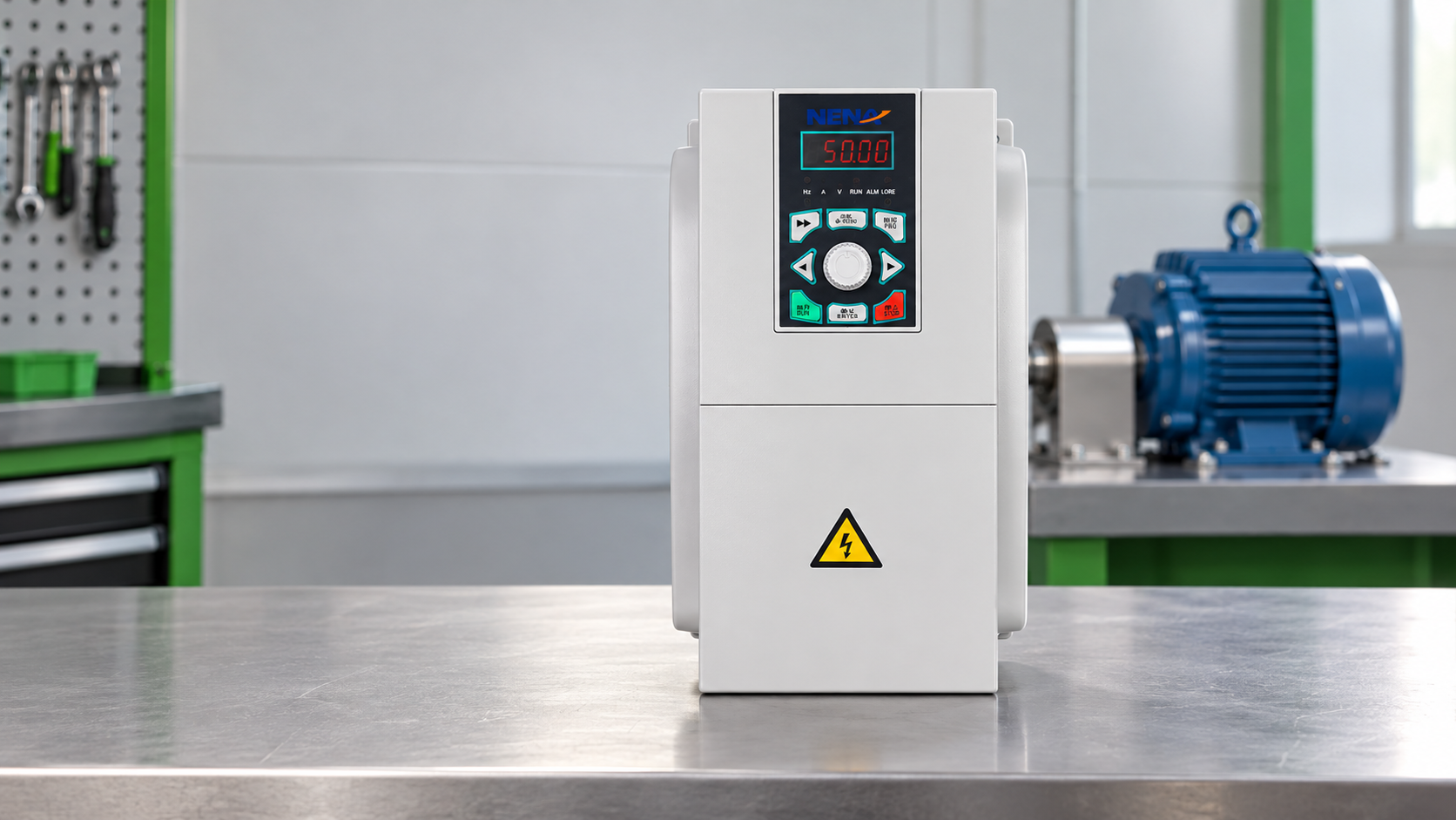
When Li Jun, a maintenance engineer in Suzhou, encountered a conveyor that jerked at every start, he lowered the mechanical throttle and restarted production. The motor still surged, the belt slipped, and the drive cabinet reported overcurrent within seconds. The reversal came after checking the motor nameplate, load torque, and acceleration ramp: the root cause was selection and commissioning, not simply a bad product.
Summary: An AC drive controls speed by converting fixed-frequency supply power into a controlled output whose frequency and voltage match the motor’s operating point. A 50 Hz motor normally runs near its rated speed at 50 Hz, while actual shaft speed also includes load-dependent slip. IEC 61800 is a drive-system standards family, not a universal product certification. Record motor current, base frequency, speed range, and load profile before selecting and commissioning a drive.
The power path has three practical stages. First, a rectifier changes incoming AC into DC. A DC link with capacitors and, where needed, inductance smooths that energy. The inverter stage then uses high-speed switching, commonly pulse-width modulation, to synthesize a three-phase output with a commanded frequency and voltage. The motor’s rotating magnetic field follows the output frequency; slip increases or decreases with torque demand.
At a 50 Hz base frequency, a command of 25 Hz generally produces roughly half the synchronous speed, but it does not guarantee half the shaft speed under load. The controller also sets acceleration and deceleration ramps so the change occurs over a defined time rather than as a step. During a repeatable no-load and loaded run, compare commanded frequency, measured current, speed, and fault history; a frequency setting alone cannot validate the machine.
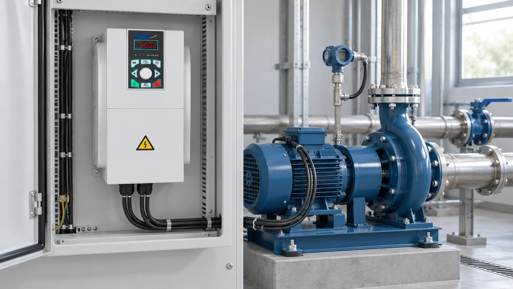
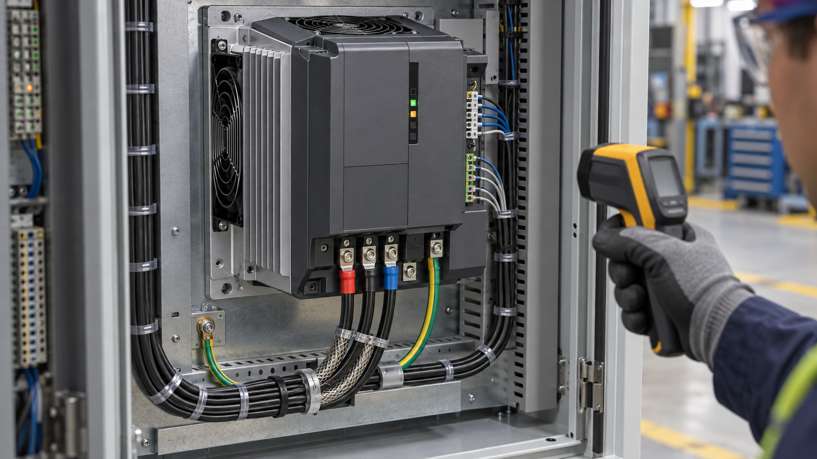 panel wiring and parameters should be reviewed before a loaded commissioning run.
A 3 phase AC drive is a power-conversion system, not a universal replacement for a starter. Collect rated voltage, full-load current, base frequency, rated speed, insulation information, braking requirements, duty cycle, and ambient temperature. Then classify the load: centrifugal fans and pumps usually follow variable-torque behavior, while conveyors, hoists, compressors, and positive-displacement pumps can require constant or high starting torque.
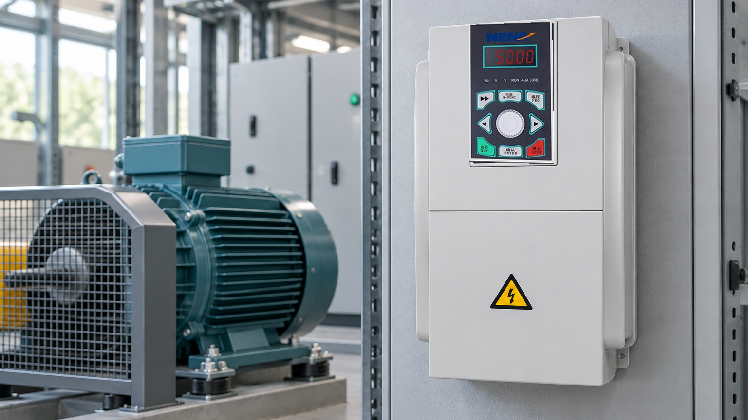
In practical commissioning, an AC drive should be treated as part of the motor-and-machine system, with its limits recorded alongside the motor data.
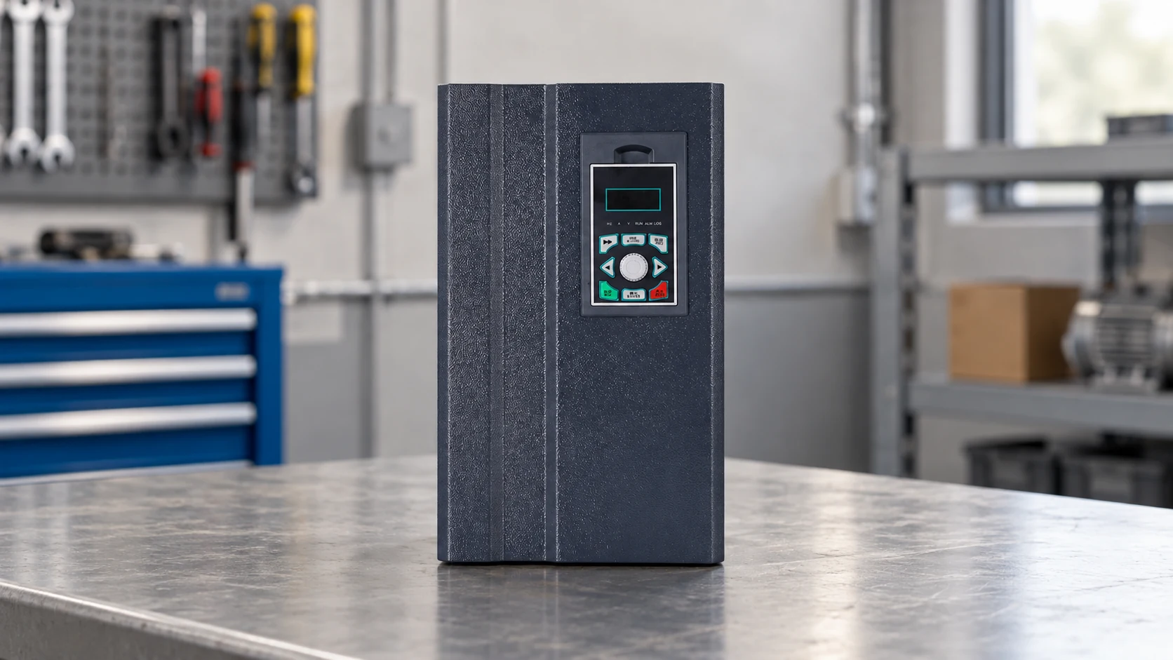
Size by motor current and overload duration rather than kW alone. A three-phase 380 V input and an 11 kW label do not prove compatibility with every 11 kW motor. Check cable length, switching frequency, motor insulation, earthing, and electromagnetic compatibility. A controlled loaded run using the motor manufacturer’s test procedure, or a documented site acceptance test, can reveal excessive current, unstable feedback, inadequate cooling, or an aggressive ramp. The AC drive frequency converter range is a category reference; the final choice should follow the complete motor and duty sheet.
Below base frequency, a volts-per-hertz profile keeps the air-gap flux approximately stable as frequency changes. Vector or sensorless-vector control estimates motor behavior to improve torque response at low speed. Above base frequency, the drive may enter a field-weakening region: speed can increase, but available torque generally falls, so the machine’s mechanical limits and process requirements become decisive.
Motor cooling is another constraint. A self-cooled fan moves less air when the shaft turns slowly, so a long low-speed run can raise winding temperature even when current appears acceptable. Set a minimum speed or add independent cooling where the motor and duty require it. Trend current, temperature, speed, and process output for at least one representative cycle; the trend is more useful than an isolated display value.
The comparison below separates what the controller can do from the costs and checks that remain in the complete installation.
| Option | Speed control | Typical fit | Key compatibility checks | Unit-cost tendency and TCO |
|---|---|---|---|---|
| Fixed-speed starter | On/off or fixed frequency | Stable-duty motor with little process variation | Starting current, mechanical shock, motor protection | Lower initial cost; can carry higher throttling, wear, or energy cost |
| Soft starter | Controlled start and stop, no continuous speed regulation | Reduced starting stress where operating speed is fixed | Bypass arrangement, start profile, load torque | Moderate initial cost; limited process control after startup |
| AC drive | Continuous frequency and voltage control | Variable flow, fans, conveyors, mixers, and process machines | Motor current, overload, cooling, EMC, braking, and feedback | Higher initial cost; may reduce process losses when correctly sized and operated |
| Servo or specialized drive | Closed-loop motion or high dynamic response | Positioning, synchronized axes, or rapid torque changes | Feedback device, inertia, tuning, machine safety | Higher system cost; justified only by motion requirements |
For a fan or centrifugal pump, a modest speed reduction can lower power demand because affinity-law relationships indicate power varies approximately with the cube of speed under comparable conditions. Static head, minimum flow, pump curve, and process limits can weaken that relationship, so measure kWh and output before claiming savings. Include filters, reactors, braking hardware, panel ventilation, commissioning, and downtime risk in the TCO calculation; any savings estimate should be labeled illustrative until site data confirms it.
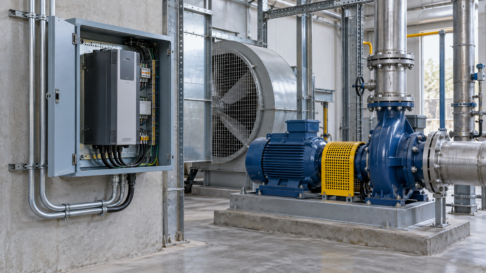
Use this procurement sequence:
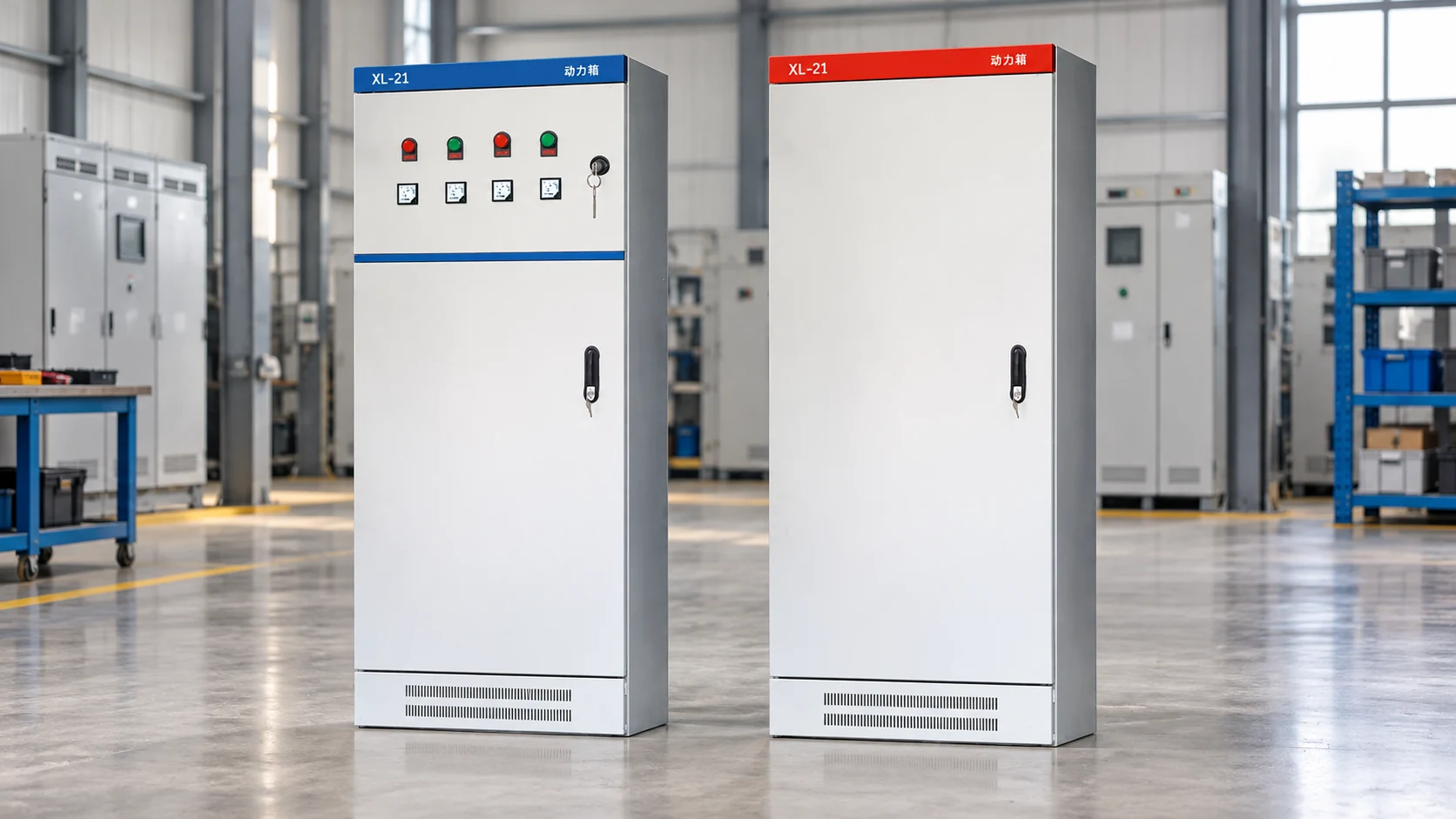
At this selection stage, NENA/Zhejiang Xinhang Electrical can be considered for configurable frequency converters, inverters, soft starters, control cabinets, and sourcing support. Evaluate the proposed configuration, documentation, testing, and service scope for the destination market; do not infer a certification or performance guarantee that has not been supplied.
Usually, yes: a VFD is an AC drive designed to vary frequency and voltage for an AC motor, and a three-phase motor is a common application. Verify motor voltage, full-load current, insulation, cooling, cable length, overload, and the drive’s input and output phase requirements first. A loaded commissioning test should confirm current, temperature, speed, and fault behavior.
Three-phase AC is used for industrial motors, pumps, fans, compressors, conveyors, and other loads that benefit from a smooth rotating magnetic field and efficient power delivery. The supply arrangement and voltage vary by destination, so confirm the local system and motor nameplate before specifying an AC drive. Protective devices and installation rules remain part of the system design.
Common categories include volts-per-hertz drives, sensorless-vector drives, closed-loop vector drives, and specialized servo or regenerative drives. The useful distinction is control objective: simple variable-torque speed control, stronger low-speed torque, precise feedback control, or energy returned during braking. Select the least complex architecture that meets the measured duty and safety requirements.
L1, L2, and L3 identify the three live phases of a three-phase AC supply; their voltage waveforms are separated by 120 electrical degrees. The labels identify phase conductors, not a promise of a particular voltage or rotation direction. Follow the drive manual, local wiring rules, phase-sequence checks, and isolation procedure before energizing equipment.
For a plain-language primer before comparing drive parameters, see what a frequency inverter is.
The right frequency is only half the answer; the right duty data makes the result repeatable. For a configured drive or application review, contact Xinhang with the motor nameplate, operating points, and required speed range ready.