VFD derating for temperature and altitude means checking how much output current the exact drive is permitted to deliver at the actual installation conditions. A catalogue kW label is not enough. Use the manufacturer’s rating basis, temperature and altitude instructions, enclosure arrangement, carrier-frequency conditions and required overload duty. There is no universal percentage that can safely be applied to every VFD, and a larger frame is only one possible response to a demanding environment.
This guide explains how to build and review the selection record. It does not assign temperature limits, altitude limits or correction factors to a NENA product without its model-specific documentation.
Identify the motor nameplate current, voltage, frequency and intended duty. Then identify the exact drive’s continuous output-current rating and any normal-duty or heavy-duty distinction. Check the input supply arrangement as well; a rating for one input configuration should not be carried into another configuration without manufacturer confirmation.
The U.S. Department of Energy’s Continuous Energy Improvement in Motor Driven Systems guidebook recommends basing adjustable-speed-drive selection on motor full-load current and matching the enclosure to the site. A power label can help locate a product family, but it does not establish available current under every environmental condition.
| Required input | What to record | Why it matters |
|---|---|---|
| Motor electrical duty | Nameplate current, voltage, motor type and required overload | Defines the motor-driving requirement |
| Exact drive rating | Model, input configuration, duty class and rated output current | Establishes the starting point before corrections |
| Temperature condition | Maximum relevant air temperature at the location defined by the manual | Room temperature may not describe air entering the installed drive |
| Site altitude | Actual installation elevation and any manufacturer voltage restrictions | Cooling and other altitude-related limits need review |
| Mounting and enclosure | Orientation, spacing, neighboring heat sources, filtering and cooling method | Changes the installed thermal environment |
| Switching and operation | Carrier mode, speed range, continuous load and overload cycle | The permitted current can depend on more than temperature alone |
For the broader motor-load review, use our motor inverter selection guide. The purpose here is to confirm the environmental boundary of that selection, rather than repeat a general drive-definition page.
The relevant ambient measurement point must come from the exact drive instructions. Air inside a loaded cabinet can be warmer than the room outside it. Neighboring equipment, recirculating discharge air, obstructed cooling paths and enclosure arrangements can further affect the air available to the drive.
Record the expected worst operating condition, including seasonal temperature and the intended enclosure state. A workshop demonstration with the door open is weak evidence for a sealed or normally closed production cabinet. Likewise, storage and transport temperature ranges should not be read as permitted full-load operating conditions.
Read the temperature curve together with its conditions. It may apply to a particular mounting orientation, enclosure type, spacing arrangement or switching mode. An alternative curve for a different cooling accessory is not permission to use that curve without the accessory. If the installation differs from the published condition, obtain a documented selection response.
Thermal evidence also needs a clear quantity. A displayed heat-sink temperature, an estimated internal device temperature and surrounding air temperature are different values. Do not substitute one for another merely because it is easier to read. Agree on the measurements and limits that will be used to validate the installation.
Air density generally falls with increasing altitude. NASA’s atmosphere explanation describes the relationship between altitude, pressure and density. That is background physics, not a VFD correction table. For air-cooled equipment, the actual manufacturer’s altitude instructions determine the available rating.
A cool mountain location should not be assumed to cancel altitude derating automatically. Some products provide an approved trade-off between temperature and altitude; others require a different correction method or impose a maximum installation altitude. Follow the stated combination rule rather than subtracting one effect from another by intuition.
Altitude can also trigger a review of the drive’s permitted voltage, supply and insulation-related conditions. A current calculation alone does not establish that every aspect of a high-altitude installation is acceptable. Send the actual site elevation and supply details to the supplier, especially when the location is outside the manual’s stated operating envelope.
If the manufacturer defines a combined current factor k, then the available continuous current is Iavailable = Ireference × k. The factor is dimensionless and both currents are in amperes. If separate factors are given, multiply, add or otherwise combine them only as the exact instructions specify; there is no universal rule that separate percentages must always be multiplied.
Consider an entirely hypothetical drive with a 40 A reference rating. Suppose its approved documentation assigns one combined factor of 0.85 for the stated installation. The available continuous current would be 40 × 0.85 = 34 A. A motor requiring 36 A would not pass that continuous-current check. The required reference rating from this simplified calculation is at least 36/0.85 ≈ 42.4 A.
The example is arithmetic, not a NENA correction factor or a recommended catalogue size. It also does not complete the selection. The next available frame must still meet the documented overload duty, voltage, control, mounting and cooling requirements. A drive with enough corrected continuous current can still be unsuitable for the acceleration or process overload.
If a manual instead gives an alternative maximum ambient temperature at a particular elevation, use that approach as written. Do not apply an additional assumed current reduction on top of it unless instructed. Keep the original curve or table with the calculation so another reviewer can reproduce the decision.

A higher carrier-frequency setting can increase inverter switching losses and alter the allowed current. Check whether the quoted drive rating assumes a default carrier, a selectable range or an adaptive mode. The VFD carrier-frequency guide explains the noise and heat trade-off; it does not supply a universal correction percentage.
Also specify overload as a complete duty: current level, duration, repetition and recovery conditions. A percentage printed on a brochure is incomplete without those conditions. Ask how the environmental correction applies to both continuous and overload performance. Do not assume that the same factor, time allowance and recovery apply across every duty class.
Motor cooling is a separate boundary. If the process needs sustained low-speed torque, the motor itself may need a suitable rating or cooling arrangement even when the VFD’s corrected current is adequate. Our minimum VFD motor-speed guide explains that distinction. Increasing drive size does not automatically restore a motor’s shaft-fan cooling.
| Possible response | What it can address | What still needs verification |
|---|---|---|
| A different or larger drive | More documented available current for the duty | Environmental limits, overload, compatibility and enclosure heat |
| Approved enclosure cooling | Lower relevant air temperature or better heat removal | Cooling capacity, monitoring, maintenance and failure response |
| Revised mounting or spacing | Recirculation or restricted airflow, where the manual supports the change | All specified clearances, orientation and assembly requirements |
| A permitted switching-mode change | A documented loss or rating trade-off | Acoustics, motor and output-filter compatibility, and process performance |
| A revised load or operating requirement | Demand beyond the available current or overload envelope | Production acceptance and machine-level implications |
A larger drive can also release more heat into the cabinet under its intended duty. A cooling solution needs its own environmental and maintenance review. Avoid treating either proposal as automatically superior without comparing the completed installation and its operating conditions.
Agree on the maximum relevant ambient condition, cabinet state, load, speed range, switching setting and overload sequence before commissioning. Record actual current, available thermal information, process output and any alarms. The test should confirm an already supported operating envelope; it should not intentionally exceed equipment limits to find a failure point.
Keep the selected model, manual revision, rating table, correction method, input assumptions and result with the cabinet documentation. Include the accepted cooling arrangement and what happens if a cooling function is lost. Where the worst seasonal condition cannot be reproduced during a short test, retain the design evidence and state that test limitation instead of declaring the condition demonstrated.
Inspection or wiring changes require qualified personnel and the site’s isolation procedure. CCOHS’s lockout and tagout guidance explains why operating commands do not establish energy isolation. Do not open a live cabinet as an informal way to improve an overheating test result.
Provide the motor nameplate, supply details, load and overload cycle, site elevation, maximum relevant air temperature, cabinet type, orientation, spacing constraints, switching preference and cooling arrangement. Ask the supplier to identify the exact curve, permitted current and remaining operating restrictions for the offered model.
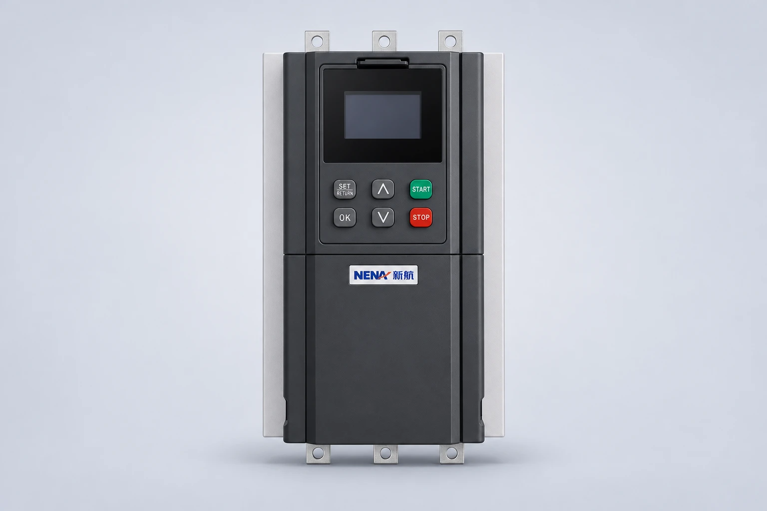
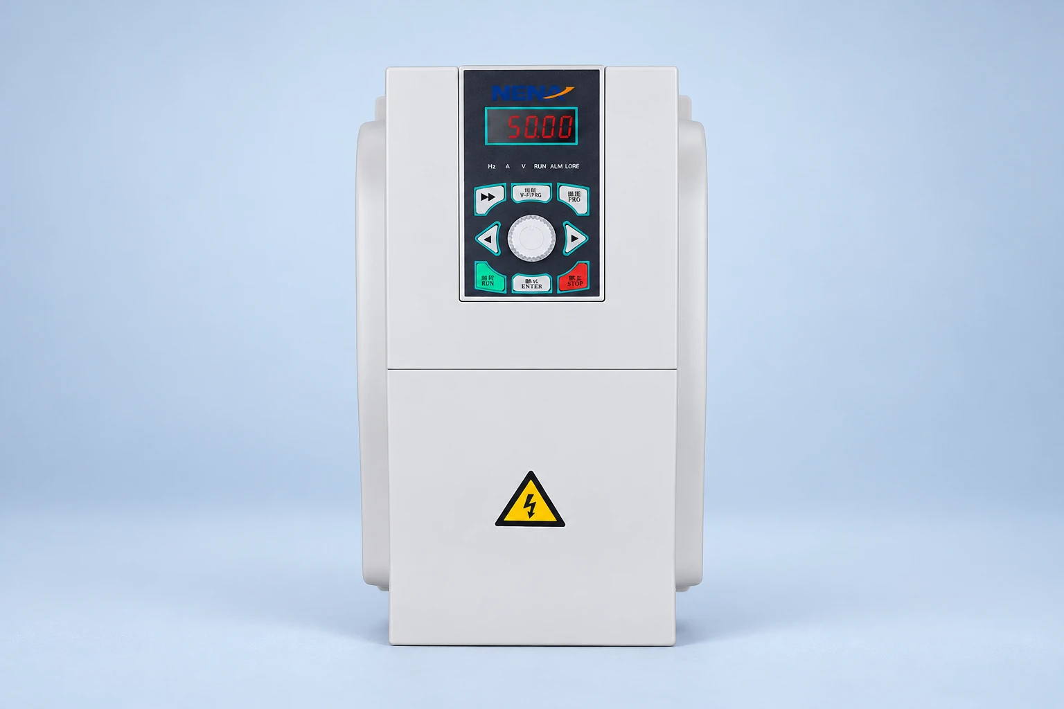
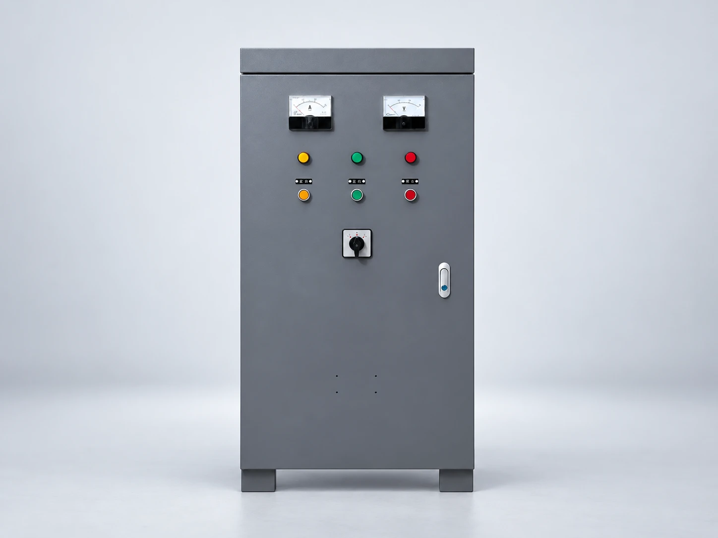
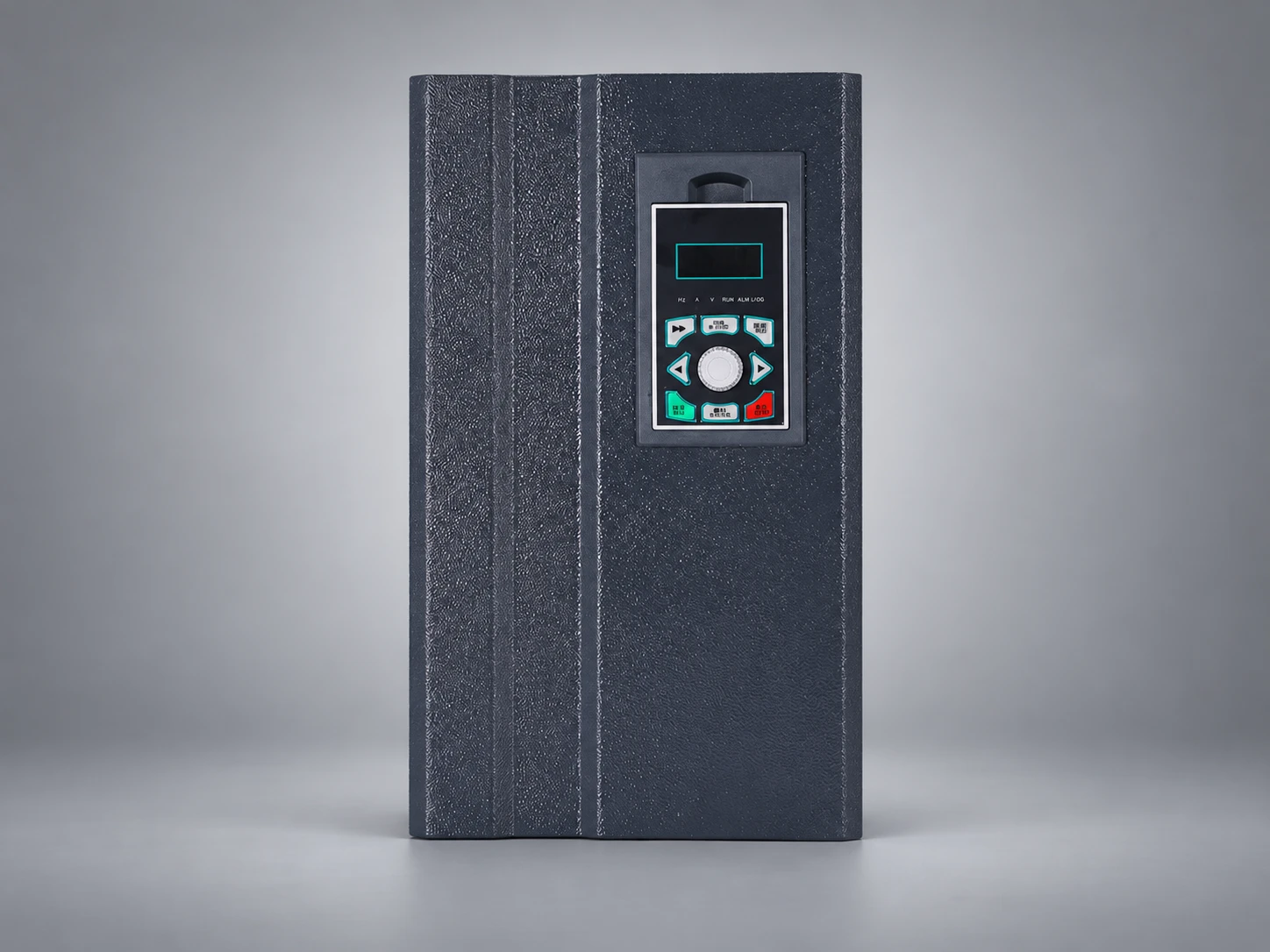
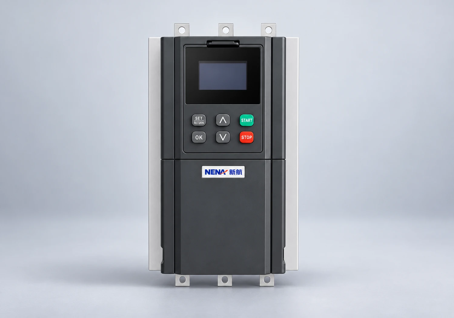
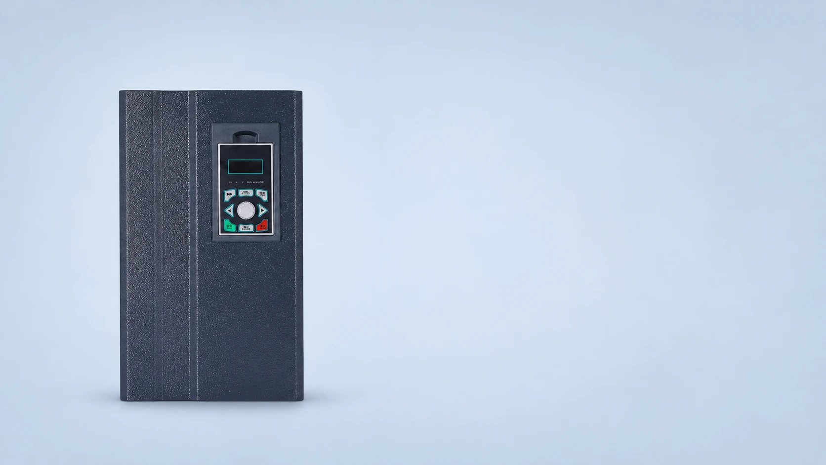
The NENA current-vector inverter is the website product reference shown in the illustrations. Those images retain its visible housing and controls; they do not demonstrate thermal performance, altitude approval or a correction factor. Request model-specific documentation before approving a selection.
This Instrumentation Unlimited video introduces VFD current derating. Treat any numerical conditions in an educational example as context, not as guaranteed limits for a NENA model. The exact drive documentation takes priority.
Watch on YouTube — Instrumentation Unlimited
No. Rating conditions vary by model, mounting, enclosure and operating mode. Read the exact documentation instead of applying common example values as universal limits.
No. Use a temperature-altitude trade-off only if the manufacturer explicitly supports it for the proposed installation. Other altitude-related restrictions may remain.
Only when that is the documented method. Some instructions use a combined factor, an alternative temperature limit or another rule. Preserve the source table and calculation.
Not necessarily. Motor thermal duty and cooling need their own assessment. Drive current capacity does not by itself establish adequate motor ventilation.