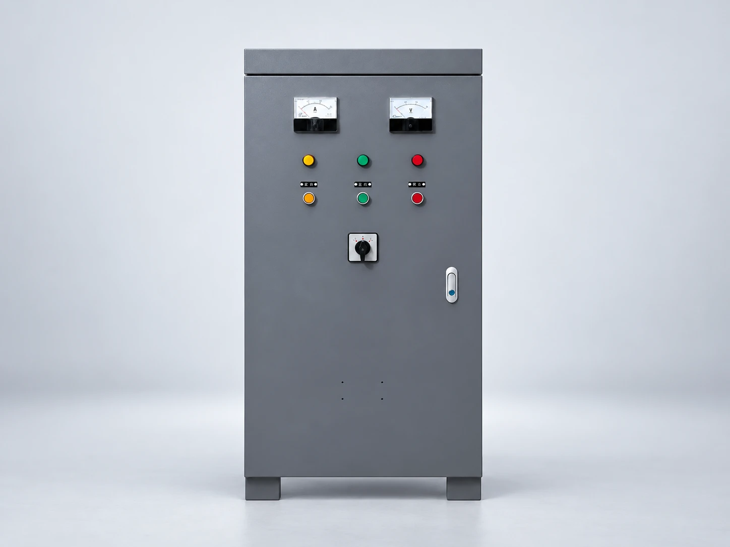
VFD cable is motor power cable selected or designed for the electrical conditions between a variable frequency drive and its motor. It must carry the required current, withstand the drive system’s voltage stress and meet the installation’s grounding, shielding and environmental requirements. Asking “what is VFD cable?” is therefore different from asking which wire size fits a motor. There is no universal cable construction, maximum length or conductor size for every drive. The selected drive manual, motor documentation, cable data and applicable installation rules must agree.
A typical AC drive system has incoming supply wiring, a drive, output wiring to the motor and separate control or feedback circuits. In this guide, VFD cable means the drive-to-motor power connection. It does not mean the incoming feeder, a communication cable or an encoder cable.
This distinction matters when reading specifications. A cable acceptable on the supply side is not automatically suitable on the output side. Similarly, motor power cable cannot substitute for a specified feedback cable simply because both connect equipment in the same machine.
For the drive’s role in the system, see our frequency inverter explanation. Establish the equipment boundaries before requesting a cable recommendation, particularly where a panel builder, drive supplier and installation contractor share responsibility.
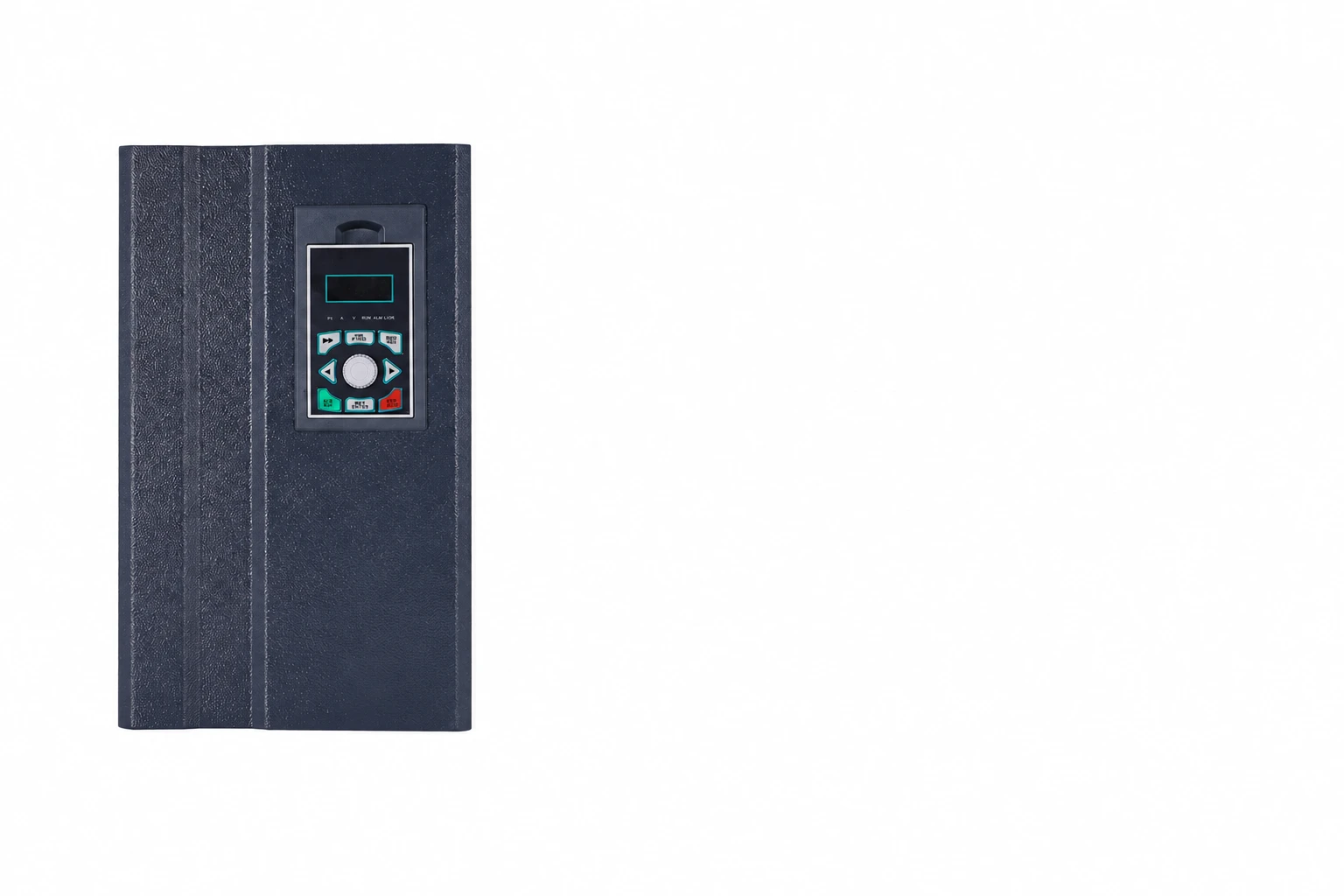
A modern PWM drive produces a switched output voltage rather than simply passing through the supply waveform. The motor current and the voltage pulses are not the same waveform. The cable and motor therefore need an assessment appropriate to that output, in addition to ordinary current-carrying requirements.
Natural Resources Canada’s motor reference guide explains that switching behavior, cable length and motor characteristics can interact to create voltage transients that stress insulation. It also discusses grounding and bearing-current issues. These are reasons to evaluate the complete drive, cable and motor combination.
Do not turn a general explanation into a universal voltage multiplier or length limit. The waveform at the motor depends on the actual system. A cable’s ordinary voltage marking, by itself, is not proof that every PWM application is acceptable.
The practical request is specific: ask whether the proposed cable’s insulation system and construction are suitable for the selected drive output, motor and installed length. Ask the responsible suppliers to identify any restrictions in writing.
| Item | What to confirm | Why it belongs in the review |
|---|---|---|
| Power conductors | Required ampacity, material, termination compatibility and installation corrections | Motor current alone does not describe the full installed condition |
| Insulation system | Suitability for the selected drive’s output conditions and motor-cable length | Current capacity does not establish resistance to repetitive voltage stress |
| Protective grounding | Required conductor arrangement, continuity and approved connections | Electrical protection must remain effective throughout the circuit |
| Shield or screen | Drive-manual requirements and compatible termination hardware | Shield performance depends on the installed connection as well as the cable |
| Jacket and mechanical duty | Temperature, moisture, chemicals, movement, bend radius and installation method | A fixed installation and a continuously flexing machine impose different demands |
| System interfaces | Glands, junctions, disconnects, motor entry and any output filter | Accessories and intermediate connections must preserve the intended arrangement |
This table is a procurement checklist, not a wiring design or a claim that every cable needs identical features. Resolve each item against the actual equipment documentation and local installation requirements. A product described as “VFD rated” still needs its exact construction, ratings and permitted use checked.
A shield or screen is part of managing electromagnetic interference in the installed system. Protective grounding has a safety function. Do not assume that a screen, drain wire or metal jacket automatically satisfies the required protective-earth connection.
Obtain the drive manufacturer’s motor-cable and termination requirements, then check the proposed cable and hardware against them. The cable specification, gland or clamp, enclosure interface and motor connection must be considered together. A good cable cannot compensate for an incompatible termination arrangement.
For a shielded system, the intended high-frequency path must be preserved through the installation. Long improvised connections, an unreviewed intermediate junction or an accessory that interrupts the specified arrangement deserve engineering review. Do not apply signal-cable shielding habits to motor power wiring without checking the equipment instructions.
If a retrofit has unexplained interference or bearing damage, avoid assuming the cable alone is responsible. Review the drive settings, grounding arrangement, motor, connections and installation history. The visible symptom identifies a reason to investigate; it does not establish a diagnosis.
Record the complete installed route from drive to motor, including intermediate boxes and service loops. A cabinet-to-machine distance on a floor plan can understate the actual cable length. Record parallel motor branches separately if the application includes them.
Ask the drive supplier which length restrictions apply to the selected cable construction and operating conditions. If an output reactor, dv/dt filter or sine-wave filter is proposed, obtain the specific approved combination and its operating restrictions. These accessories perform different tasks and should not be treated as interchangeable names.
An incoming line reactor is also not automatically a solution to a motor-side cable problem. State which side of the drive an accessory serves and what issue it is intended to address. This prevents a quotation from appearing complete while leaving the output-circuit review unresolved.
Carrier-frequency changes can alter system behavior, but they do not remove the need to check cable and motor limits. Our VFD carrier-frequency guide discusses that separate setting decision. Do not treat a quieter motor or the absence of an immediate trip as proof that the insulation and grounding arrangement are acceptable.
Begin with the drive’s output-circuit instructions and the motor data. The responsible designer must determine conductor ampacity under the applicable rules, including the relevant duty and installation conditions. Conductor temperature rating, termination limits, grouping, ambient conditions and the selected wiring method can affect the result.
Next, evaluate voltage-related requirements and cable-system compatibility. A conductor can have adequate current capacity while its insulation or installed arrangement remains unsuitable for the drive output. That is why an online wire-size calculator cannot complete the selection by itself.
Finally, verify physical fit. Confirm terminal acceptance, cable outside diameter, bend radius, entry hardware and available space. A cable that meets an electrical schedule can still create an installation problem if it cannot enter the cabinet or terminate as instructed.
No numeric cable-size example is offered here because the supply details, jurisdiction, equipment instructions and installation conditions have not been specified. A useful quotation should list those inputs and the resulting cable selection rather than conceal assumptions behind a universal kW-to-cable table.
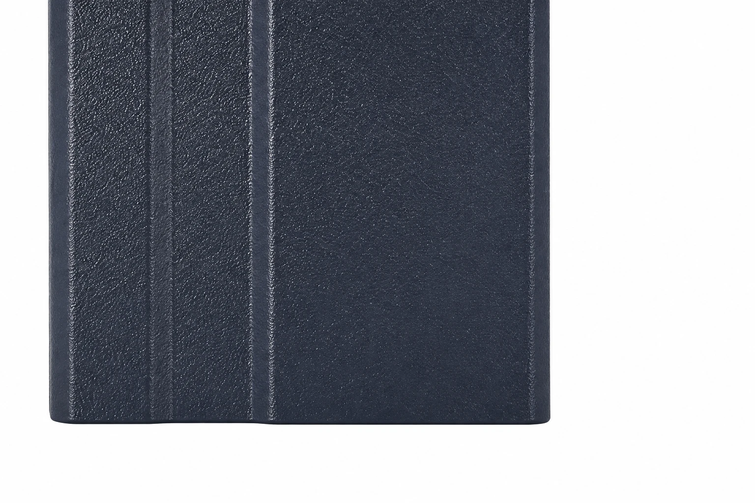
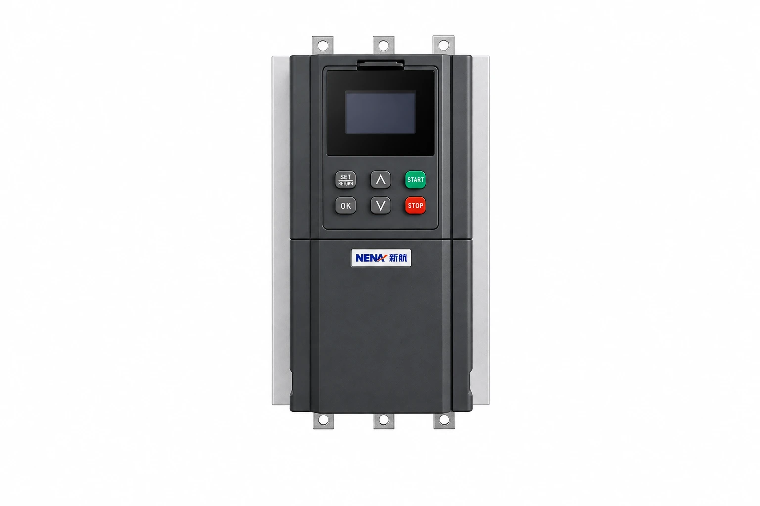
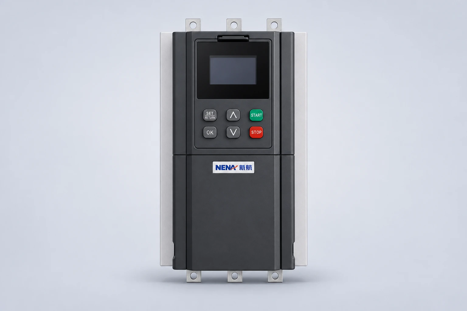
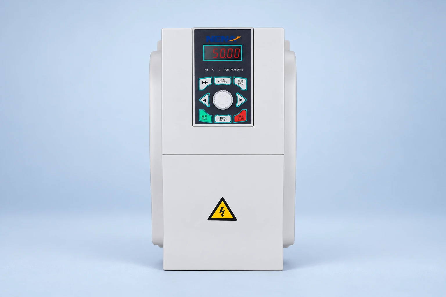
A NENA current-vector inverter is one product reference for a drive-system enquiry. Confirm the exact supplied model and its installation manual. The exterior photograph does not establish terminal capacity, cable-entry dimensions, shielding provisions or approval for a particular cable.
Map the motor-power route alongside the control and feedback routes. Check the manufacturer’s separation and crossing requirements rather than choosing a distance from an unrelated installation. Identify where cables enter enclosures, where they move with the machine and where they can encounter heat, liquid or mechanical damage.
Include junction boxes, local isolators and connectors in the review. If the installation needs an intermediate disconnect, obtain the approved arrangement and operating sequence. Do not assume it is acceptable to switch a drive’s loaded output as though it were an ordinary supply circuit.
Before inspection or modification, follow an equipment-specific isolation procedure, including stored energy. CCOHS lockout/tag-out guidance distinguishes operating controls from energy-isolating devices. A dark display or keypad stop is not evidence that the circuit is safe to touch.
The U.S. Department of Energy’s motor-system guidebook supports collecting motor and operating information before equipment decisions. For a retrofit, retain the old cable identification, drive settings and service history as well. These records help reviewers distinguish a design issue from an installation or maintenance change.
At commissioning, verify the installation against the approved drawings and equipment instructions. Record the cable identification, installed length, termination arrangement, accessories and final settings. Qualified personnel should perform the specified inspections and tests using suitable methods; do not apply insulation-test equipment through connected electronics unless the manufacturer explicitly permits the procedure.
For broader operating preparation, our guide on using a VFD with a three-phase motor covers the surrounding application questions. Keep the cable review as a documented part of that system assessment.
This NPTEL IIT Delhi lecture introduces sinusoidal PWM and three-phase converter operation. It explains the background to a drive’s switched output; it is not a cable-installation tutorial or a source of cable ratings.
Watch on YouTube — NPTEL IIT Delhi
Only when its exact construction and installed arrangement meet the drive, motor and installation requirements. An acceptable current rating alone is insufficient. Ask the equipment and cable suppliers to confirm the proposed output-circuit application.
No. Requirements depend on the selected drive system, environment, installation and applicable rules. Check the equipment instructions for cable construction and termination requirements rather than assuming one shield arrangement fits every project.
There is no single limit for all systems. The selected drive, cable, motor, operating settings and output accessories determine the permitted arrangement. Obtain the applicable limit for the actual combination before ordering or extending the cable.
No. An appropriate cable and grounding arrangement can be part of the system response, but bearing problems require diagnosis. Motor construction, operating conditions and other electrical or mechanical causes must also be reviewed.