VFD carrier frequency is the switching rate associated with the inverter’s pulse-width modulation. It is different from the output frequency that determines the motor’s rotating-field speed. A higher carrier setting can change or reduce an objectionable motor whine, but it can also increase inverter switching losses and require a lower permitted output current. The appropriate setting comes from the exact drive’s rating tables, motor and cable requirements, thermal conditions and a controlled operating check. There is no single quietest frequency that is automatically safe for every motor-drive installation.
This guide explains the trade-offs for industrial motor-drive users. It does not prescribe a universal kHz value, alter a product rating or replace the drive manufacturer’s installation instructions.
A VFD produces a motor supply using rapidly switched voltage pulses. The desired lower-frequency voltage component and the motor’s response to the pulse pattern are distinct from the switching rate. In a basic sinusoidal PWM explanation, a reference waveform is compared with a higher-frequency carrier to form switching commands. Actual industrial drives can use other modulation methods and automatic adaptations.
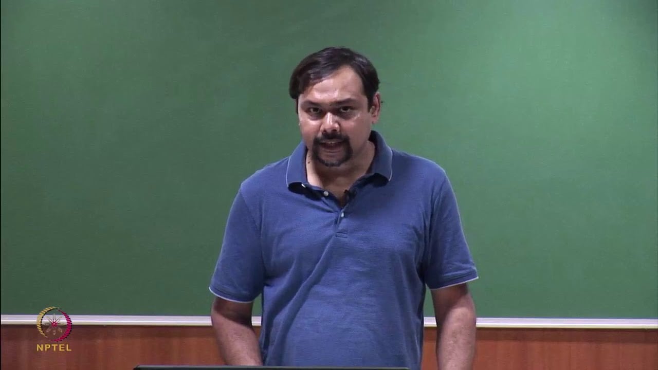
NPTEL’s lesson on sinusoidal pulse-width modulation introduces this distinction. Our VFD operating-principle guide gives the broader power-conversion context.
| Quantity | Usual unit | Meaning | What it does not establish |
|---|---|---|---|
| Output fundamental frequency | Hz | The motor electrical-frequency command | Actual shaft speed under every load |
| Carrier or switching frequency | kHz, or Hz in some menus | The PWM switching timescale, as defined by the drive | A new motor-speed command |
| Switching-edge rise time | Time, commonly discussed in microseconds | How quickly an individual voltage edge changes | The same thing as carrier frequency |
| Motor shaft speed | RPM | The mechanical rotation of the rotor | The PWM pulse rate |
For illustration, 4 kHz means 4,000 carrier cycles per second. At a 50 Hz reference, the simple carrier-to-reference ratio is 4,000/50 = 80. Raising that illustrative carrier to 8 kHz doubles the ratio to 160; it does not change the 50 Hz command. The precise switching-event pattern depends on modulation, so this is not a count of every transistor transition.
For a four-pole induction motor, a 50 Hz fundamental corresponds to 1,500 RPM synchronous speed through ns = 120f/p. The loaded rotor runs below the rotating field during normal motoring. Changing only the carrier setting is therefore not a method of selecting shaft speed. Also check the units: confusing a kHz carrier menu with a Hz speed reference can lead to an entirely different parameter change.
Electromagnetic forces associated with the switching waveform can excite audible vibration in a motor. Changing the carrier changes parts of that excitation spectrum. Whether the installation sounds better depends on the motor, modulation, operating speed, load and mechanical resonances. A setting change can alter the pitch without eliminating every source of noise.
Before adjusting the drive, distinguish electrical whine from bearing damage, a loose cover, a vibrating base, cooling-fan noise or a driven-machine problem. Listen and measure at consistent operating conditions. A sound that tracks shaft RPM or appears at one narrow mechanical speed range deserves a different investigation from a tone that responds directly to a carrier-setting change.
Do not assume that selecting a value above a commonly quoted human hearing boundary will make the whole installation silent. Other waveform components and mechanical noise remain possible, and hearing sensitivity varies. Use an agreed acoustic criterion in the actual working area. A brief phone recording can help document a complaint, but does not replace a suitable sound measurement where formal acceptance is required.
Power semiconductors dissipate energy during switching transitions. More switching cycles per second can increase that part of the loss. Texas Instruments explains the relationship in its motor-driver switching-loss application note. Its example concerns 48 V automotive MOSFET systems; it illustrates the principle and does not provide industrial VFD current ratings or permitted settings.
A useful conceptual expression is Psw ≈ Ecycle × fsw, where switching loss is in watts, energy per switching cycle is in joules, and frequency is in cycles per second. With an illustrative constant 2 mJ per cycle, 4,000 cycles/s gives 8 W and 8,000 cycles/s gives 16 W. These are hypothetical values for a simplified switching element, not the total loss of a three-phase inverter.
Real switching energy varies with voltage, current, temperature, device behavior and modulation. Conduction losses, cooling-fan power and other losses also remain. Doubling carrier frequency therefore does not establish that the total drive temperature rise or complete drive loss will double. Use the actual manufacturer’s thermal and current-rating information for selection.
If the manual requires derating at the selected carrier frequency, compare the resulting available output current with the application’s continuous and overload requirements. Include ambient temperature, altitude, enclosure conditions and any other specified reductions using the manufacturer’s method. Do not invent a fixed percentage per kHz or assume the full nameplate output remains available at every setting.
The motor receives a switched waveform, not a perfect sinusoidal voltage. Cable characteristics, cable length, motor insulation and the output network can affect stresses and interference. A carrier adjustment does not remove the need to follow the drive’s cable and motor requirements. Natural Resources Canada’s electric-motor reference guide discusses inverter-related waveform effects, motor compatibility and installation considerations.
Carrier frequency and switching-edge steepness must not be treated as interchangeable controls. Reducing the repetition rate does not necessarily slow each voltage edge. Likewise, a higher carrier frequency does not certify a gentler motor-terminal waveform. Where cable length or motor insulation is a concern, obtain a documented review of the complete drive-cable-motor combination.
An output reactor, dV/dt filter and sine-wave filter are different devices. Ask which, if any, is required for the proposed installation and what switching-frequency range it permits. Some filters depend on specific operating conditions. A quiet motor is not evidence that a filter or cable requirement has been met, and a generic accessory list is not a compatibility statement.
| Stage | Record or check | Reason |
|---|---|---|
| Identify | Exact drive model, firmware, motor, control mode and current carrier setting | Parameter meanings and allowed ranges vary |
| Establish the baseline | Speed, load, output current, ambient conditions, alarms and noise location | Changes must be compared at equivalent operating points |
| Check ratings | Permitted output current and overload at the proposed setting | Acoustic improvement must not consume required current capacity |
| Check the output circuit | Cable type and length, motor suitability and filter restrictions | A parameter change cannot substitute for installation compatibility |
| Validate | Representative operation, temperature evidence, stability and process output | An unloaded short trial may miss production limitations |
| Handover | Approved setting, test results and conditions for future changes | Prevents undocumented settings from becoming an assumed standard |
Start from the approved configuration rather than a forum’s preferred kHz value. Have the responsible person confirm the permitted adjustment method, including whether the motor must be stopped. Make one authorized change at a time and retain a rollback record. If a fault appears or operation becomes unstable, follow the agreed stopping and diagnostic procedure.
Evaluate the result at representative speed and load and under the intended enclosure conditions. Do not leave a cabinet open to obtain a favorable thermal result if normal service requires it closed. Confirm that any available temperature indication represents the quantity being assessed; a displayed heat-sink value is not the motor winding temperature.
Some drives automatically change effective switching frequency with operating conditions. Establish whether the parameter is a fixed value, a maximum or part of an adaptive mode. A changed tone during acceleration can be normal for an adaptive strategy, but the explanation must come from the actual model documentation rather than an assumed feature.
If a motor overheats only during sustained low-speed loaded operation, check motor cooling and torque duty as well as drive settings. Increasing carrier frequency is not a substitute for independent motor ventilation or an appropriate motor rating. Our minimum VFD motor speed guide explains that separate operating boundary.
If the process needs tighter speed regulation, review control mode, motor data, tuning and feedback. A higher switching rate alone is not a promise of position accuracy, starting torque or zero-speed holding capability. Similarly, intermittent nuisance trips need their actual fault record investigated; changing several parameters until the trip disappears can hide the cause.
Repeated drive overheating also calls for inspection of load, cooling paths, contamination and enclosure conditions. Any inspection, rewiring or servicing belongs under the applicable isolation procedure. A carrier setting is an operational parameter, not a safety function or permission to touch the power circuit.
For a NENA quotation, provide motor voltage and rated current, load type, speed range, overload requirement, operating hours, ambient temperature, altitude, cabinet arrangement, motor cable details and the acoustic acceptance point. Include any existing output filter and the customer’s reason for requesting a particular carrier frequency.
The NENA current-vector inverter product provides a relevant product reference. Ask for the exact model’s carrier-frequency options, derating table and output-circuit requirements. This article does not assert a supported kHz range or current capacity for that product. For the full specification process, use our motor inverter selection guide.
This NPTEL IIT Delhi lecture explains sinusoidal PWM and a three-phase converter. It provides independent background for understanding the carrier; it is not a parameter-setting tutorial for a particular NENA drive.
Watch on YouTube — NPTEL IIT Delhi
Not by itself. Motor speed depends on the fundamental output frequency, pole count, load and control behavior. The carrier concerns the switching pattern used to produce the motor supply.
No. A higher setting may improve an objectionable tone but increase switching losses or reduce permitted drive current. Confirm the model’s ratings, motor and output-circuit requirements before changing it.
It is not a universal remedy. Cable length, voltage edges, insulation and filter compatibility require a complete application review. Follow the documented drive-cable-motor limits.
Do not assume so. Their power stages, cooling, modulation and rating conditions can differ. Compare exact model documentation and application duty rather than copying the number.