Duplex pump control panel alternation changes which of two pumps receives the lead duty, helping distribute operating use. It is different from lag control, which calls the second pump when demand exceeds the first pump’s capacity or when an agreed backup condition occurs. A panel with two pump indicators does not automatically provide every alternation, fault-transfer or alarm function. Specify the operating sequence and test each required response. This guide focuses on level-controlled pump-down systems; pressure boosting and tank-filling applications need their own documented control sequence.
The lead pump starts first during a normal demand cycle. The lag pump starts when another defined condition requires additional pumping. A standby pump is available to replace an unavailable duty pump, but the term does not establish whether both pumps may run together. A project can require duty/standby operation, duty/assist operation or a combination. Put that requirement into plain written statements before discussing relays or controller brands.
For a pump-down sump, rising liquid level usually creates a start request and falling level ends the cycle. The second start threshold may request another pump if the first is unable to reduce the level quickly enough. The designer must confirm that simultaneous operation is hydraulically useful and electrically permitted. Two identical pumps in parallel do not automatically provide twice the single-pump flow at the actual system head.
A useful independent explanation appears in Thompson Rivers University’s drainage training material, which describes duplex sump arrangements. Its teaching example explains the concept; it does not prescribe the number of floats or control logic for every installation.
Alternating after every completed cycle is straightforward, but equal cycle counts do not guarantee equal operating hours. One cycle may last much longer than another. If wear balance is the objective, runtime-based selection may be more suitable. Specify whether the system alternates by cycle, elapsed time or accumulated operating hours, and define when the change is allowed.
Some installations need a manual lead preference for maintenance or operational reasons. State how that preference interacts with automatic alternation. A maintenance selection should not silently erase the required standby response, and a failed pump should not repeatedly be selected as lead without an agreed recovery condition. The owner’s sequence should describe both normal operation and the exceptions.
Record the distinction between command and proof. An output telling pump one to start is not evidence that water is moving. A running contact, current measurement, pressure or flow signal can provide different levels of confirmation. Choose the evidence needed for the process and define a reasonable response time using the equipment and hydraulic design.
| Condition | Required response to define | Evidence during acceptance |
|---|---|---|
| Normal lead request | Start the available lead pump after applicable interlocks. | Correct pump command and agreed running proof |
| Cycle complete | Stop according to the approved level sequence and update alternation. | Correct stop response and next-cycle lead selection |
| Lag demand | Start the second pump if simultaneous operation is permitted. | Both pumps respond without violating the design limits |
| Lead unavailable | Apply the specified backup and alarm behaviour. | Unavailable pump is excluded and required alarm appears |
| High level | Raise the specified local and remote alarm; apply agreed pumping action. | Alarm reaches the intended recipient or monitoring point |
| Power restored | Resume or await reset as required by the risk assessment. | Documented restart order and stable control response |
Utility requirements show why the sequence must be explicit. The Jackson County Utility Authority specification includes duplex control and failure-handling provisions. Those are requirements for that authority’s context, not universal settings to copy into another site’s controller.
Float switches and continuous level instruments provide different information. A float normally changes state near a physical level, while a transmitter provides a varying measurement interpreted by the controller. Either arrangement needs a documented response to invalid signals and maintenance isolation. Avoid assuming that a continuous sensor automatically removes the need for an independent alarm or backup measure.
The designer must select start and stop levels with wet-well volume, inflow, pump capacity, submergence and allowable motor starts in mind. Narrow level separation can cause frequent cycling. Excessive separation may use storage that should remain available for abnormal inflow. The appropriate values depend on the site, not on the panel’s maximum number of inputs.
Sensor installation matters as much as the logic. Turbulence, obstructions, cable restraint, foam and solids can affect a level device. Record the intended mounting and access arrangement. Acceptance testing should demonstrate the required input states without exposing personnel to a confined-space or electrical hazard. Use qualified personnel and approved test methods.
A two-pump installation still may have common points of failure: supply, level sensor, controller, discharge pipe or alarm communication. Alternation alone does not remove those dependencies. Identify the failure cases that the project must tolerate and ask whether the proposed arrangement actually addresses them. A second motor is useful only when the remaining system can operate it under the relevant condition.
State the required response to overload, seal alarm, temperature alarm and missing running proof where these signals are provided. Some faults may permit an automatic transfer; others may require a stop and manual investigation. The panel supplier should implement the approved sequence rather than applying one generic rule to every signal.
Clarify how an unavailable pump returns to service. Automatic fault clearance, local reset and operator authorization are different arrangements. Record whether alternation resumes immediately or at the next completed cycle. A clear recovery rule prevents unexpected repeated starts after an intermittent problem.
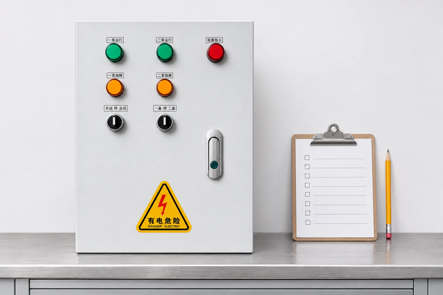
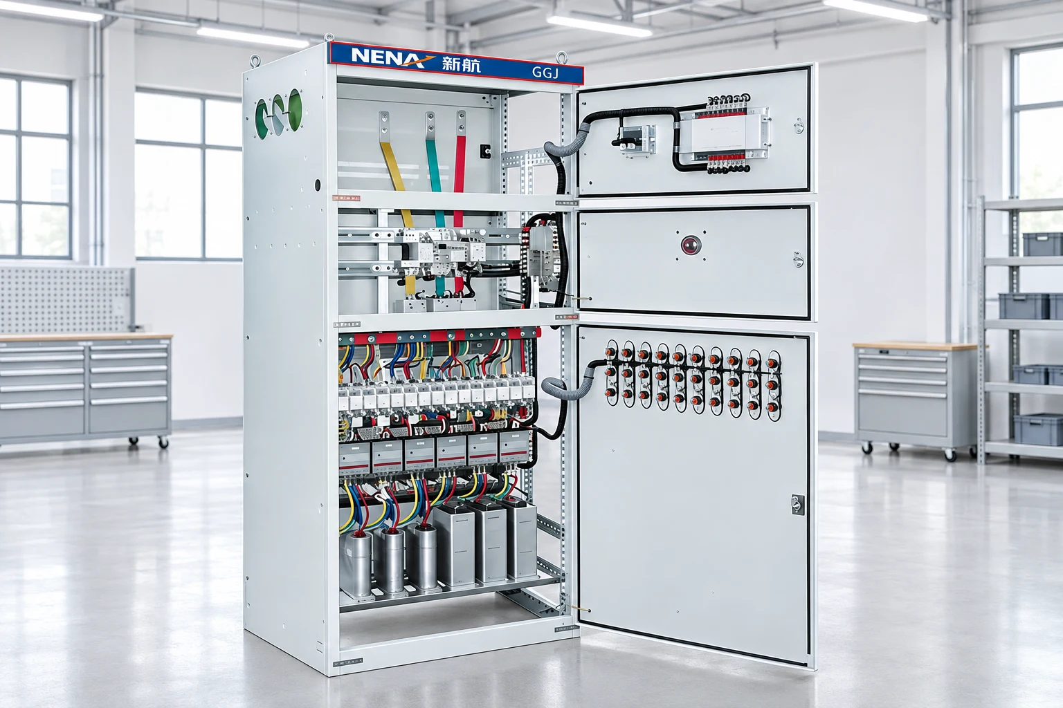
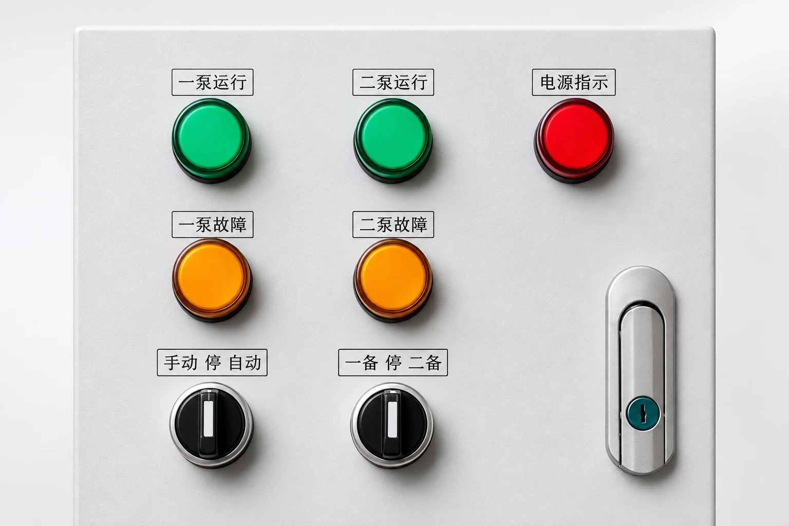
NENA’s duplex pump control panel provides a relevant starting point for a two-pump enquiry. Its visible lamps and selector switches identify the product, but do not establish its internal logic, alarm communications or redundancy. Request a model-specific schematic, input/output list and written operating sequence.
Provide each motor’s nameplate, supply characteristics, starting method, available fault level and environmental conditions. Include the sensor types, required alarm outputs, control voltage and cable distances. If both pumps can run at once, the supply and panel ratings must cover that agreed duty. If they cannot, the interlock must be explicit and tested.
The broader motor-control cabinet selection guide helps define the supply boundary. Where variable speed is part of the design, review the VFD pump selection guide. If frequent cycling affects a soft-started motor, the soft-starter ramp-time discussion explains why extending acceleration is not a substitute for correcting the process sequence.
Prepare a test sheet with the initial state, simulated input, expected output and actual result. Test at least two complete normal cycles so that both lead selections are demonstrated. Check lag demand separately from a high-level alarm, even if the design uses a combined signal. Record any deliberate delays and verify their purpose against the approved sequence.
Then test an unavailable lead pump, a pump removed by its selector, the specified sensor-failure cases and restoration of power. Confirm local indications and remote alarm delivery at the agreed endpoint. Hearing a local sounder does not establish that a remote operator received the notification. Restore every test bypass and temporary input before handover.
Finish with a controlled wet test where practical. Verify actual level changes, pump discharge behaviour and stopping levels. Save the final settings, schematic, test record and maintenance instructions. These records let the operator distinguish a sensor problem from a control fault and make later changes without losing the original operating intent.
During planned maintenance, pump one may be selected off while pump two remains available. The acceptance test should show what happens on the next normal demand, on additional lag demand and when pump one is restored. The operator needs to know whether the system simply alarms, changes its lead selection or requires a manual acknowledgement. None of those responses follows automatically from the presence of two selectors.
Record the temporary operating limitation as well. One remaining pump may maintain normal service but be unable to handle peak inflow. An alarm at that condition should be understandable to the operator and reach the agreed monitoring point. Once maintenance ends, verify that temporary overrides are removed and the normal alternation sequence is restored.
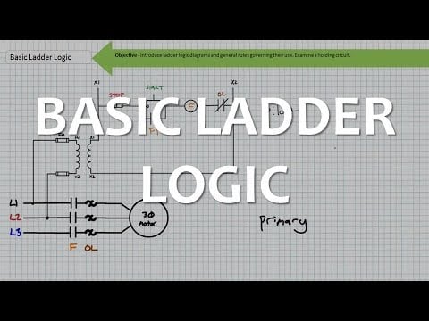
The educational video below explains control concepts relevant to automatic pump operation. It supplements the sequence table; it does not provide a wiring diagram for this NENA panel or replace its approved instructions.
No. Alternation changes which pump leads. Lead-lag control defines when another pump joins operation or responds to a specified condition.
No. Alternating every cycle balances cycle selection, while the duration of those cycles can differ. Runtime balancing needs a suitable measurement and control strategy.
Only if the approved hydraulic and electrical design permits that response. Define the action explicitly rather than assuming it from the word duplex.
Use an approved acceptance test that makes the lead pump unavailable, applies the relevant demand and checks the required transfer, alarms and subsequent recovery.