Ring main unit cable testing needs a coordinated plan for the cable, its terminations, the switchgear and any connected devices. Before approving the work, establish the cable identity, both ends of the test boundary, the permitted access arrangement and the applicable test method. Test voltage and duration must come from the approved cable-system specification and equipment instructions. An RMU nameplate rating alone is insufficient. This guide helps project engineers and purchasers prepare an acceptance package and ask the right questions. It is not a switching sequence or an instruction for applying test voltage to an installed network.
State whether the project concerns a newly installed cable, an existing circuit after repair or a planned condition assessment. Include the cable construction, service history, length, joints and termination details in the request. The responsible testing organization needs this information to propose the method and acceptance criteria. Calling every activity a “hipot test” can hide important differences in the actual scope and in the equipment included.
Separate cable testing from the RMU factory acceptance work. A factory report for the switchgear does not automatically cover the installed cable route. Equally, a cable test report does not establish that every switchgear operating function has been accepted. The broader RMU and switchgear comparison explains the equipment context. Keep the cable work as a clearly identified part of the overall commissioning plan.
Ask who owns the final decision on the test specification. Depending on the project, the network operator, design engineer and equipment suppliers may all need to review different parts. Put the agreed responsibilities in writing before a test contractor arrives. The contractor should receive an approved scope rather than be expected to resolve contradictory purchase documents on site.
Prepare a marked one-line drawing showing the circuit identifier, local end, remote end and every included joint or branch. Link the drawing labels to the physical equipment register. Request confirmation of which terminations remain connected and which equipment is excluded. For a ring arrangement, a name such as “incoming cable” may be ambiguous unless the feeder reference and both ends are recorded.
Ask the authorized network team to review all possible sources affecting the work boundary. The HSE safe working practices guide discusses identification, isolation, proving dead and additional precautions for high-voltage work. The site’s competent personnel must establish and control the safe work condition under applicable rules. A drawing used for procurement does not itself authorize access or testing.
For planning, list the documents the testing team must receive: the current one-line, cable schedule, termination instructions, RMU manual and relevant operating authority requirements. Record unresolved differences between drawings. If the field labels and the schedule do not agree, make that an explicit hold point for the responsible team rather than asking the contractor to infer the correct circuit.
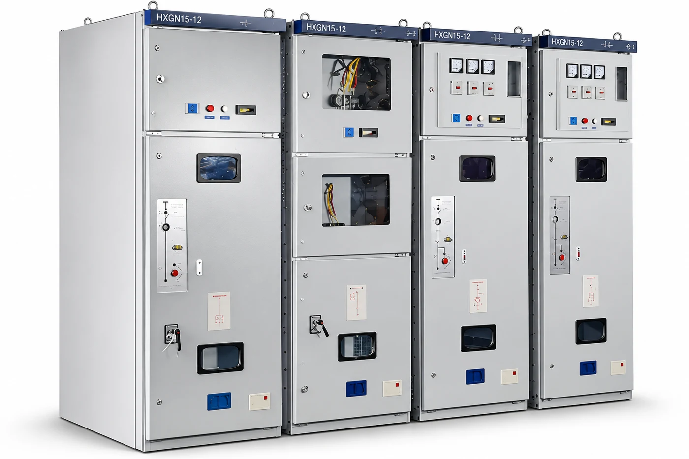
Do not infer a cable test interface from a photograph, a voltage indicator or the fact that another RMU has a similar front panel. Request the manufacturer’s drawing of the actual access arrangement and its permitted use. Ask whether the ordered unit includes the required provision and what accessories, adapters or termination arrangements the approved method needs. A generic catalog drawing should be identified as such.
Have the designer and relevant suppliers review every device that could be exposed during the proposed test. Ask about voltage transformers, surge arresters, sensing arrangements and other connected apparatus where applicable. The review should identify the approved inclusion or exclusion of each item. Avoid copying a disconnection list from a different cabinet; the actual circuit and equipment instructions govern the decision.
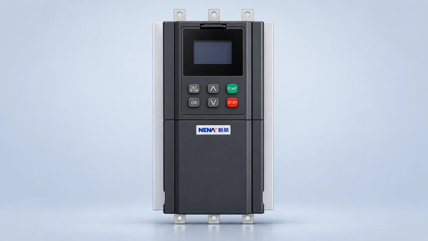
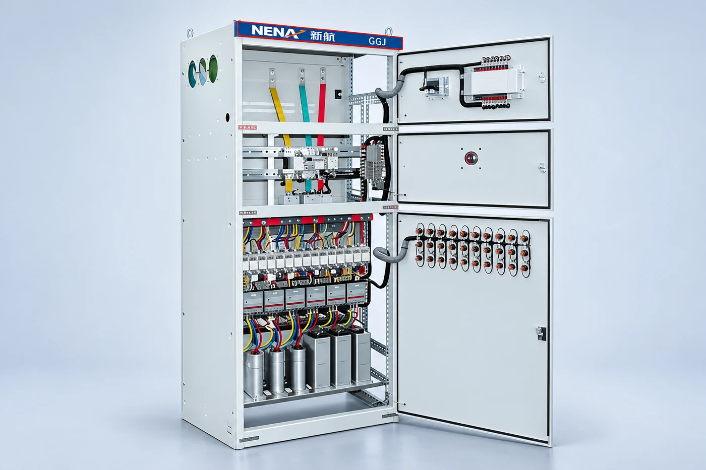
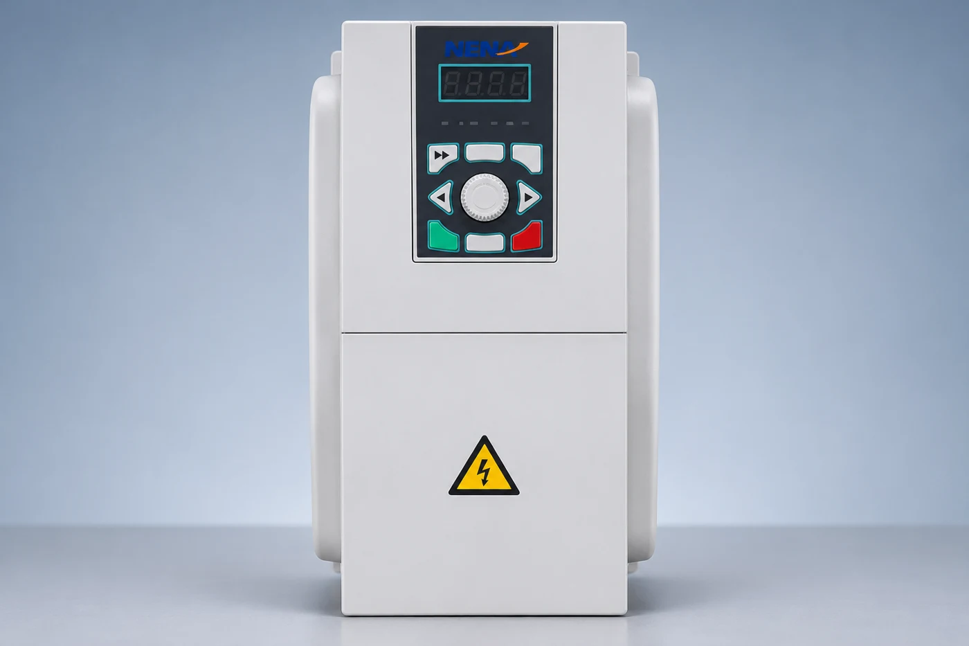
For a NENA HXGN ring network switchgear inquiry, send the feeder arrangement and cable test requirements with the quotation request. Ask NENA to confirm the delivered configuration against those requirements. The visible four-section product illustration on this page does not establish a particular cable test point, adapter rating or approved operating sequence.
The following matrix is a proposed document-review aid. It intentionally provides no default test voltage. Each row should lead to a project-specific answer from the responsible authority.
| Planning question | Required input | Approval output |
|---|---|---|
| What cable system is included? | Cable type, length, joints, terminations and service history | Identified test section and purpose |
| How is test access provided? | Actual RMU and termination instructions | Approved interface and accessories |
| Which apparatus sees the test? | Marked circuit diagram and device schedule | Reviewed inclusion and exclusion list |
| Which method and limits apply? | Network requirements and cable-system specification | Authorized method, waveform, voltage and duration |
| What permits handover? | Results, exceptions and reinstatement records | Signed acceptance and operating responsibility |
Insulation resistance measurement, sheath integrity assessment and a specified withstand test answer different questions. The approved plan should name the test rather than relying on an informal label. It should also state the instrument requirements and how each result is evaluated. A numerical value without the test conditions and connection reference is difficult to assess or compare later.
Western Power’s high-voltage XLPE cable commissioning form separately records phasing, insulation resistance, sheath integrity and VLF work. Its instructions prohibit high-voltage DC hipot testing of HV XLPE cable within that specified scope. It also distinguishes handover stages. This illustrates why method selection must follow the applicable cable-system rules; its values and instructions are not universal settings for every NENA RMU installation.
Ask the test organization to identify the reference supporting each selected limit and the revision used. If a report states an AC value, make clear whether it is expressed as rms or peak and identify the waveform. If two documents disagree, request a written resolution. Do not select the larger number simply because it appears to demonstrate a more demanding test.
Before mobilization, ask the test coordinator to check the completeness of the package. Include the equipment identifiers, approved method, responsible contacts, required access provisions and the process for reporting exceptions. Specify how the team will record changes discovered in the field. The planning objective is to avoid an improvised scope after the outage has started.
Where an operating authority controls the network, make the interfaces explicit. The testing organization should know who controls the circuit, who accepts the test section and who receives it after work. The actual permits and switching instructions remain with the authorized organization. A purchaser’s witness request should align with that arrangement and should not create conflicting directions to technicians.
The article on RMU interlock documentation addresses a related equipment review. For this cable work, request confirmation that the proposed access method follows the actual manufacturer’s instructions. Do not treat the ability to open a compartment as proof that the cable is ready for testing, and do not use a general article to bypass the equipment’s access controls.

Ask for a report template with the circuit identity, cable details, instrument identification and calibration reference. It should capture the actual method, settings, duration, connection reference, readings and final assessment. Include a place for interruptions, abnormal events and deviations from the approved plan. A report containing only “pass” gives a future reviewer little basis for understanding what was assessed.
Agree how failures and incomplete work will be handled. For example, an unidentified remote termination or missing equipment instruction can make a test scope unresolved before any voltage is applied. Record the open issue, the person responsible and the evidence needed to close it. Do not turn “test postponed” into “test passed” because the cabinet otherwise looks complete.
Retain the report together with the approved drawing and any revisions created during the work. If the circuit is later extended or repaired, the new team needs to know which section the earlier report covered. A stable document reference is more useful than a photograph of a test-set screen detached from the circuit record.
HSE’s switchgear safety guidance addresses the responsibilities of owners and operators and the use of equipment-specific maintenance information. For this acceptance plan, ask the responsible team to document the final configuration and release conditions. Completion of a test is one input to handover; it does not replace the site’s authorization to return the circuit to service.
Keep reinstatement evidence separate from the test result. Request confirmation that the installation matches the approved final drawings and that any temporarily affected apparatus has been dealt with under the authorized method. The report should identify outstanding restrictions. Do not infer completion solely from an instrument being removed or a contractor leaving the site.
Where the RMU serves a packaged installation, coordinate the cable records with the prefabricated substation commissioning context. Environmental and access conditions belong in the wider handover, while cable test acceptance remains tied to its own scope. Send the final package to the owner’s document custodian so it can be retrieved by feeder identifier.
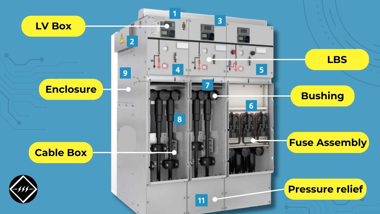
TheElectricalGuy’s educational RMU overview helps readers recognize the equipment’s broad functional arrangement. It provides background for discussing the drawings; it does not authorize a test connection or supply a switching procedure for the pictured unit.
Watch on YouTube — Gaurav J – TheElectricalGuy
No. The approved method must consider the cable system, terminations, connected apparatus and applicable project requirements. Request the responsible engineer’s documented limits.
No. Confirm the actual delivered configuration and the relevant manufacturer’s instructions. Do not infer an interface or rating from a photograph or another product.
No. It covers the defined test scope. Other equipment checks, reinstatement and the operating authority’s release conditions remain separate acceptance items.
Include the approved scope and drawings, cable and equipment identity, method and instrument records, actual results, deviations, assessment and signed handover information.