VFD motor cable length has no single safe maximum that applies to every drive and motor. Accept the installed route only after checking the exact drive instructions, motor insulation requirements, cable construction, electromagnetic compatibility conditions and any output device. Include the complete routed length, not merely the straight-line distance between equipment. If the documents do not cover the proposed circuit, obtain written engineering confirmation before ordering the cable or energising the installation.
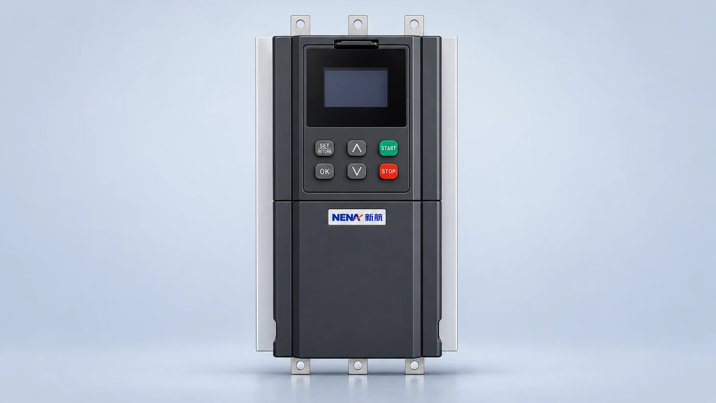
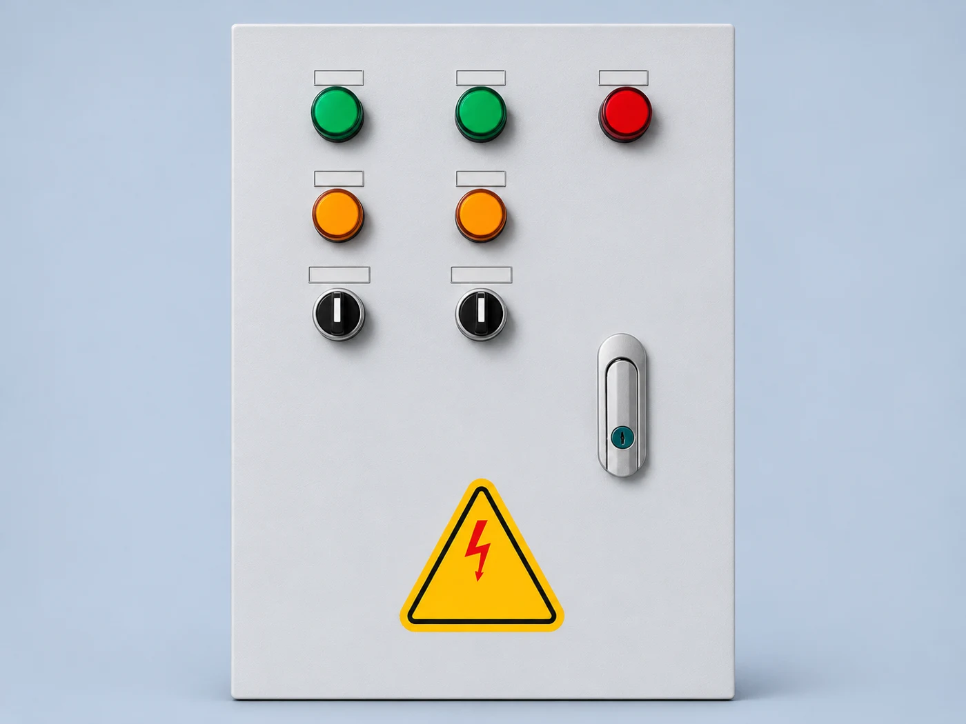
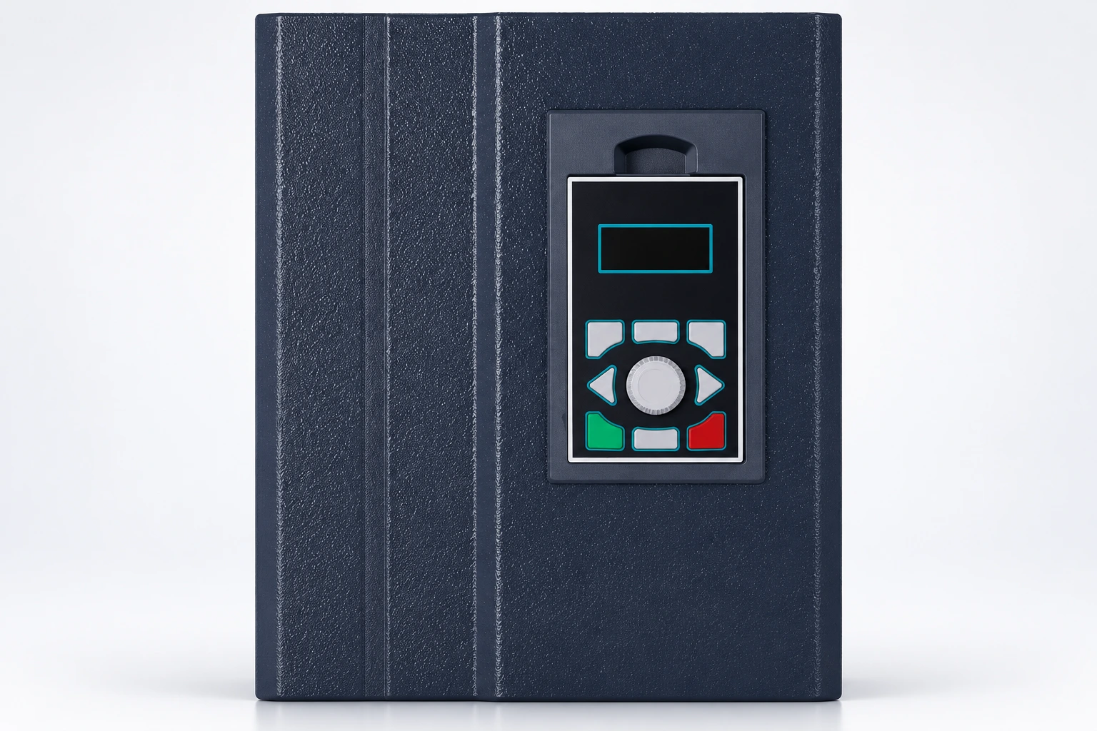
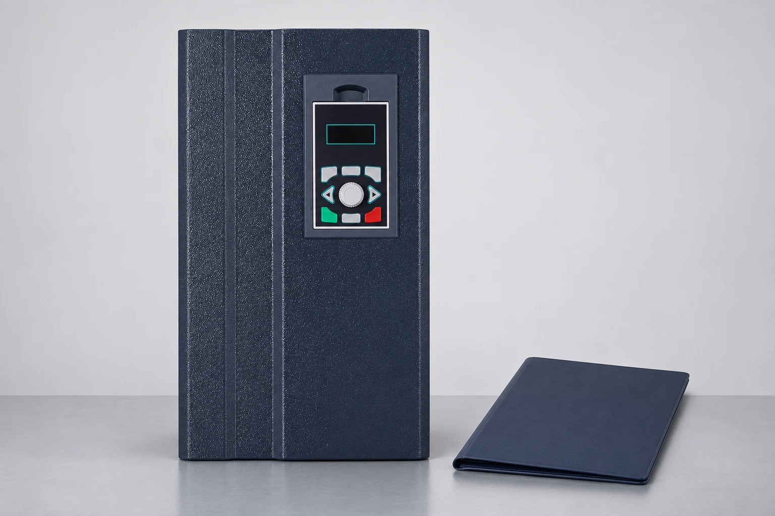
This guide focuses on the length review. The VFD cable overview explains cable construction and procurement more broadly. The illustrated NENA 860S current-vector inverter is relevant product context, but its photograph and power range do not establish an approved cable length for your motor.
A drive supplies a pulse-width-modulated output rather than the same waveform provided by a conventional sinusoidal supply. Rapid voltage changes travel along the cable and encounter the motor. Differences between cable and motor characteristics can produce reflections. The resulting motor-terminal stress depends on the system, so the distance alone does not describe the whole problem.
Natural Resources Canada’s VFD reference discusses voltage stress associated with switching waveforms, motor insulation and cable length. Treat its general discussion as a reason to perform a system review, not as a cable-length approval for a particular NENA model. It cannot replace the manufacturer’s installation limits.
There are several questions to answer separately: can the drive operate with the connected cable, can the motor tolerate the terminal waveform, and does the installation satisfy the required EMC arrangement? Passing one check does not automatically pass the others. A cable with adequate current-carrying capacity can still leave the output circuit outside another documented condition.
Prepare a route drawing that starts at the drive output and ends at the motor terminals. Include vertical rises, cable tray deviations, service loops, local isolation equipment and intermediate junctions. Identify the measurement method and whether the length is provisional or as installed. A purchasing estimate and an installation acceptance record serve different purposes.
When a route changes, update the register before closing the change request. A relocation that looks minor on a floor plan may add a considerable cable run through existing trays. Avoid approving the drive on the original estimate and then treating the revised route as an unrelated construction detail. The electrical reviewer needs the final arrangement.
Show multiple motor branches explicitly where the application permits them. Do not hide a branched circuit behind the length of only its longest route. The applicable drive documentation must define how cable loading and length are assessed for that arrangement. If the manufacturer does not permit or describe the proposed topology, stop the comparison and obtain an approved design.
The table below is an original review template. It deliberately contains no universal distance values. Fill the accepted value or condition from the exact manual, approved engineering response or project specification. Record the document revision and relevant section so another reviewer can reproduce the decision.
| Review item | Evidence to collect | Acceptance question |
|---|---|---|
| Drive output limit | Exact model, rating, manual revision and applicable cable condition | Does the proposed complete circuit fit the documented limit? |
| Motor compatibility | Motor identification and permitted inverter supply conditions | Has the motor supplier accepted the proposed waveform and circuit? |
| Cable route | Installed length, construction, joints and branch layout | Does the reviewed drawing match the actual installation? |
| EMC condition | Required environment, shield termination and approved installation arrangement | Is the specified EMC condition valid at this length? |
| Output device | Approved reactor or filter, location and operating restrictions | Do drive, device and motor requirements agree? |
| Commissioning evidence | Approved checks, final settings and unresolved exceptions | Can the responsible engineer release the circuit? |
A component on the incoming supply side does not automatically solve a problem on the motor side. The purchasing list should identify whether each reactor or filter belongs at the drive input or output and what problem it is intended to address. Similar names and similar-looking enclosures are not sufficient evidence that parts are interchangeable.
For an output reactor, a dV/dt filter or a sine-wave filter, request the approved application data rather than choosing solely by motor current. Ask about the drive model, supply voltage, switching-frequency conditions, output-frequency range, cable arrangement and motor requirements. The device supplier and drive supplier should agree on the configuration before the project relies on an extended route.
Physical installation also belongs in the review. A specified device needs adequate space, cooling, mounting and access, along with the correct location in the circuit. Confirm what cable lengths apply on either side of it. Do not assume that adding an unreviewed component creates unlimited cable capability or removes the need for motor compatibility checks.
An existing motor may have operated successfully on a direct supply for many years. That history does not establish compatibility with a proposed inverter circuit. Collect its identification and available insulation information, then ask the motor supplier or responsible engineer to review the intended duty. An undocumented motor should appear as an open item rather than an assumed approval.
The ASHRAE chapter on motors, controls and variable-frequency drives explains that reflected pulses can create high peak voltages and discusses the importance of motor and cable characteristics. It also addresses grounding paths. These principles help explain why an ordinary distance rule cannot describe every installation.
Record the required EMC environment and the installation conditions supporting it. Cable shields, terminations, bonding and routing need to follow the applicable instructions. A longer route may require a separate review of the manufacturer’s EMC conditions even when another output-circuit limit is satisfied. Do not present a successful motor run as evidence that the EMC requirements have been met.
Bearing currents are a related but distinct topic. If the project also needs that assessment, use the VFD bearing-current guide to frame the questions. A remedy selected for insulation stress should not be described as resolving every common-mode or bearing problem without supporting evidence.
First verify the facts. Confirm the model, manual version, length measurement and cable construction. Check whether the cited limit applies to the actual installation condition. Do not compare an unshielded-cable value against a shielded route or borrow a limit from a different voltage or drive family. Correcting the comparison may change the engineering question.
Then request an approved solution. Possible design discussions include shortening the route, relocating equipment, selecting an appropriate output device or changing the drive-motor combination. None is automatically suitable. Review access, environment, maintenance, voltage drop, cable capacity and application requirements with the responsible designer before choosing an option.
If switching frequency is part of the proposed solution, record the agreed setting and restrictions in the handover documents. Lowering it without a review can affect noise, performance and other application conditions. The carrier-frequency article explains that separate decision; it does not grant permission to exceed a cable limit.
The commissioning plan should refer to the reviewed circuit and acceptance criteria. Confirm final cable routing, device identification, shielding and bonding against the approved design. Record final parameter settings and document any substitutions. An installation with a different output filter or motor should return to the reviewer rather than inherit the original acceptance by default.
Specialist measurements of fast output waveforms require appropriate instruments, methods and competence. A normal multimeter reading or a short trial run cannot establish the peak stress at the motor. This article does not provide a live-testing method. Where measurements are required, let the responsible specialist define the safe procedure and interpretation.
Keep insulation testing separate from the drive electronics and follow the relevant equipment instructions. Do not apply an insulation tester through connected power electronics. The test plan must identify the isolation boundaries, reconnections and checks needed before restoration. Record any test that was not performed and why, so the final report does not imply a broader acceptance than was obtained.
A useful enquiry includes the drive model, supply, motor nameplate and available insulation data, cable specification, full route drawing, proposed output device, operating range and EMC requirement. Ask the supplier to identify the approved configuration and its limitations in writing. Preserve that response with the equipment order and final installation records.
For example, “the motor is far from the cabinet” invites a general answer. A marked route drawing with a confirmed cable type and equipment identities lets the supplier assess the actual proposal. If any of those inputs remain provisional, identify the uncertainty and state when the final review must occur before release.
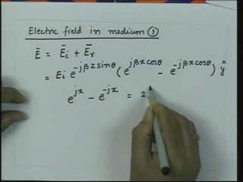
The NPTEL lecture below explains reflection from a conducting boundary as background physics. It helps visualise why a travelling wave can return from a boundary; it does not model a particular VFD cable or specify an installation limit. Use the drive and motor documentation for engineering acceptance.
No. The accepted length depends on the documented drive, motor, cable, EMC and output-device conditions for the complete installation.
No. Motor compatibility is one check; drive capability, EMC conditions and any output-device restrictions still need review.
Do not assume that. Input and output devices serve different circuit locations and purposes; use an approved solution for the actual problem.
No. A running motor does not by itself verify insulation stress, EMC compliance or every condition in the installation instructions.