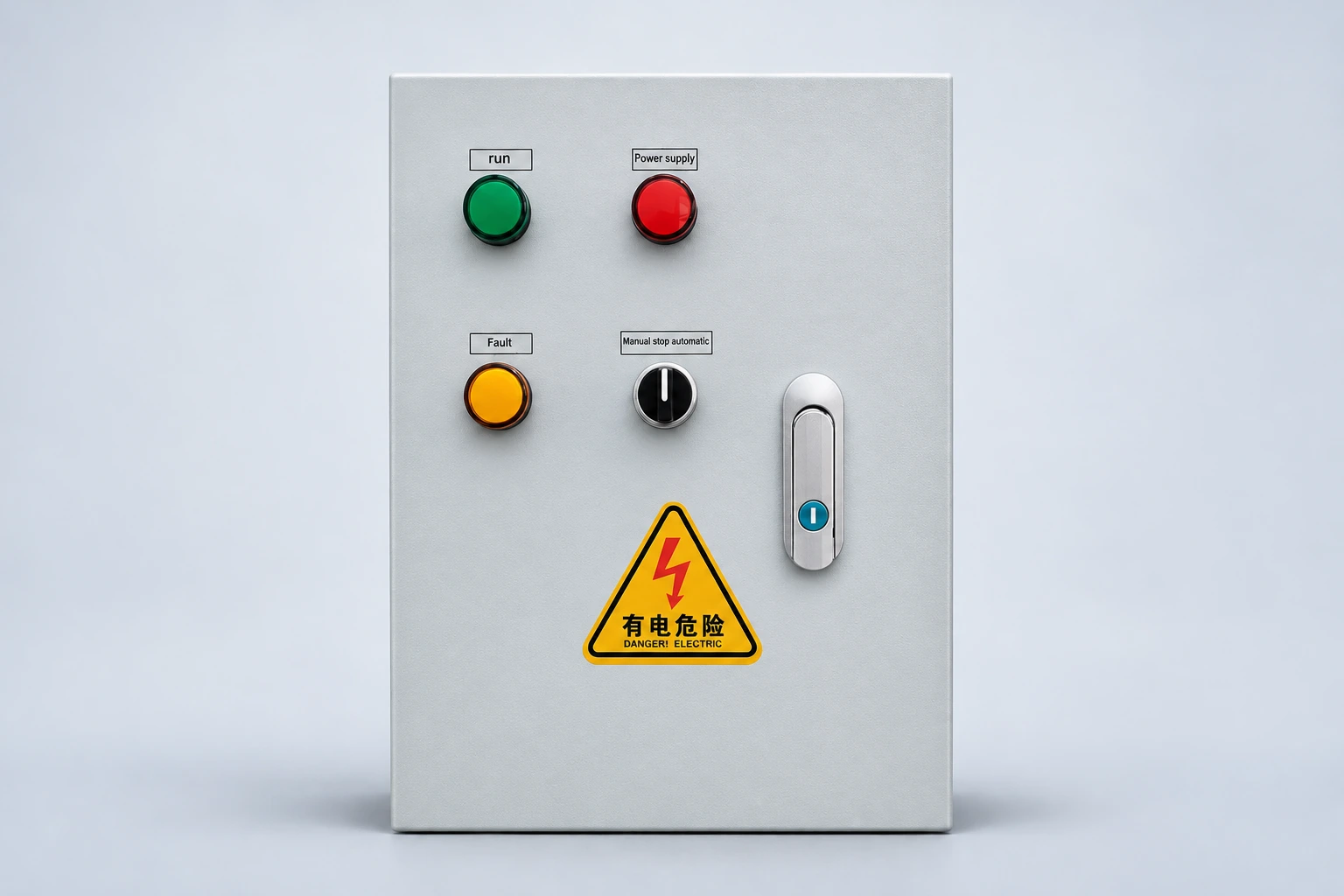
A VFD motor insulation resistance test needs a defined test boundary before an instrument is connected. The motor, its cable and the variable frequency drive are different items; a test intended for motor insulation must not be applied indiscriminately through connected drive electronics. Ask a qualified technician to identify the equipment, follow the exact manufacturers’ instructions, establish safe isolation and document what is included in the measurement. A stopped motor or dark keypad is not proof of a safe circuit. This guide explains how an industrial owner can specify and review the work without copying a universal test voltage or resistance limit.
Start with the reason for the test. A motor returning from storage, a machine exposed to moisture and a system with a recurring earth-fault indication present different questions. Record the symptom and operating history before components are disconnected. A drive alarm is useful evidence, but its name alone does not identify a defective motor winding or distinguish the motor from a cable problem.
The work request should identify whether the owner needs a condition trend, investigation of a specific fault, or acceptance after repair. Include the relevant previous results and the decision that depends on the new test. A simple request to “megger the VFD” leaves both the test object and the intended decision unclear. Replace that wording with an identified component and an approved method.
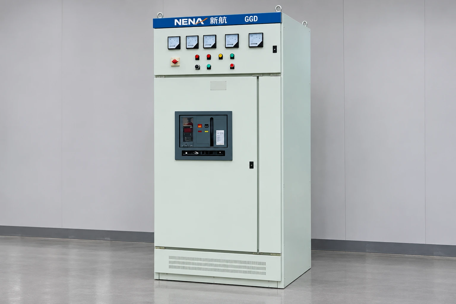
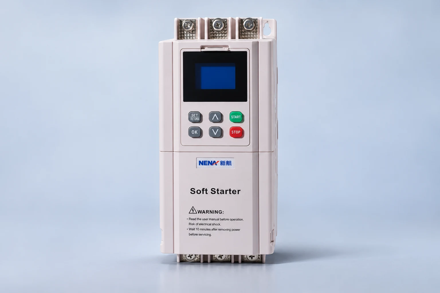
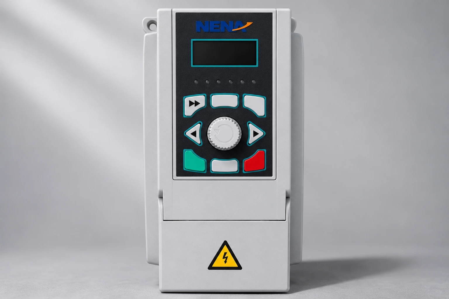
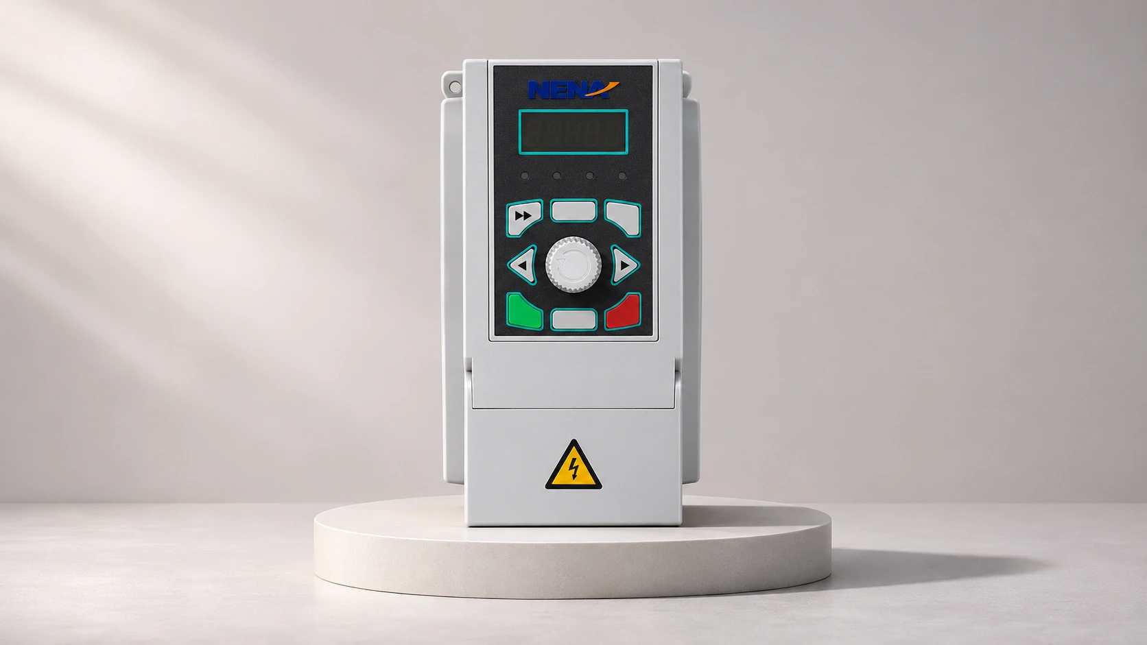
The NENA 820 general-purpose inverter provides the product context for the illustrations. Its keypad and enclosure do not establish a field insulation-test procedure. The actual drive revision, motor details, cable arrangement and connected accessories must be identified from the supplied documentation before the technician selects a method.
A measurement only answers a question about the circuit connected to the instrument. When a motor and cable remain connected together within an approved test boundary, their combined insulation path may influence the result. A low reading cannot automatically be assigned to the motor. If the investigation requires separate component evidence, the qualified team must plan the necessary separation and testing under the applicable instructions.
Drive power circuits, control modules, sensors, filters and other accessories can require different treatment. Establish what is connected at both ends of the proposed test path. A drawing that shows only the main motor conductors may omit an accessory relevant to the test. Resolve uncertainty with the equipment supplier instead of assuming a terminal label defines the whole circuit.
Manufacturer documentation found during research uses different motor-and-cable arrangements. That difference is why this article does not supply a generic terminal-by-terminal method. Use the exact manual for the supplied assembly and record the approved boundary on the job sheet. Do not treat a procedure for another supplier’s drive as an instruction for the NENA product pictured here.
Testing is electrical work even when the machine is not producing output. Identify the supplies, stored energy and possible movement relevant to the system. Follow the site’s authorized isolation and verification procedure before access or disconnection. The person carrying out the work must understand both the electrical system and the limitations of the test equipment.
The HSE safe-working guidance provides a framework for planning electrical tasks and establishing appropriate safe conditions. It does not turn an online checklist into permission for unqualified work. Include control supplies and any other sources identified in the equipment documentation rather than assuming that the main stop command removes every hazard.
After a test, the test object may require discharge and verification before handling or reconnection. The instrument and equipment instructions determine the appropriate method and precautions. Keep responsibility for that stage explicit in the work plan. An automatic function displayed by a tester should not replace the technician’s required verification of the actual condition.
The US Department of Energy’s motor and drive system sourcebook describes insulation-resistance checks as part of motor maintenance and discusses moisture and contamination. A result can guide further investigation; it does not independently establish the complete mechanical, electrical and operational condition of the machine.
Insulation resistance is different from winding resistance, and neither should be confused with every possible winding-insulation diagnostic. Record the actual test name. If a report says only “resistance passed,” ask which property was measured, with which circuit and under what conditions. A continuity indication from an ordinary meter is not the same evidence as an approved insulation-resistance test.
Likewise, a satisfactory result for a disconnected motor does not prove that the drive, cable terminations, protection or control sequence is satisfactory. The return-to-service decision must consider the work scope and any remaining fault evidence. Avoid interpreting one successful test as a certificate for the whole drive system.
| Record | What to specify | Why the owner needs it |
|---|---|---|
| Component identity | Motor, cable or other defined test object | Prevents assigning a combined result to one component |
| Boundary | Included connections and separated equipment | Explains what was exposed to the test |
| Method | Approved procedure, instrument and relevant settings | Makes comparison and review possible |
| Conditions | Temperature and other conditions required by the method | Provides context for a change in reading |
| Acceptance basis | Applicable equipment guidance and responsible review | Avoids a copied universal pass number |
| Disposition | Further investigation, repair or authorized release | Connects the observation to a controlled decision |
This qualitative table defines the evidence expected from the contractor. It does not choose a test voltage, duration or pass threshold. Those values must be suitable for the particular equipment and approved procedure. A complete record also identifies the technician and date, and preserves the original result rather than only a rounded value in a summary email.
A trend is useful only if its records describe comparable test objects and methods. A previous reading from the motor alone cannot be directly compared with a later reading that includes a long cable without acknowledging the changed boundary. The same applies when a motor has been repaired or an accessory disconnected between tests.
Temperature and moisture context can matter to interpretation. Retain the conditions required by the method, together with any approved corrections or qualifications. Do not silently replace the measured result with an adjusted number. Keep both the original evidence and the reviewer’s interpretation so another engineer can understand the decision later.
If the result is unexpected, stop at a defined investigation point. Confirm the identity, configuration and instrument setup under the approved procedure before condemning a component. An unusual reading is not a reason to keep increasing the applied voltage. Escalate the question to the responsible specialist and record the additional evidence requested.
The test report should not end before the system is restored to its intended configuration. Record removed connections, identification marks and any settings affected by the work. Reconnection, terminal checks and guarding must follow the equipment instructions and approved release process. An undocumented temporary arrangement should not become the production configuration.
Plan the operating verification separately from the insulation measurement. Define who authorizes power restoration, which functions are checked and what stops the trial. Review fault indications and the original symptom under suitable conditions. Keep any untested operating cases visible instead of assuming a brief run proves the entire process.
The OSHA hazardous-energy control rule provides US workplace context for servicing and controlled restoration. Its applicability must be assessed for the actual task and jurisdiction. A normal run command, selector position or software inhibit does not replace the required energy-control process.
Provide the drive and motor identification, approved drawings, cable information, fault history and previous test records. State whether the motor has been idle, repaired, exposed to water or moved between machines. Request a written test boundary and acceptance basis before the outage. This gives competing service quotations a comparable scope.
The VFD cable guide explains the cable’s role in the system. The separate discussions of motor cable length and bearing currents address other engineering questions. Neither a cable-length calculation nor an insulation-resistance result alone diagnoses every drive-related motor problem.
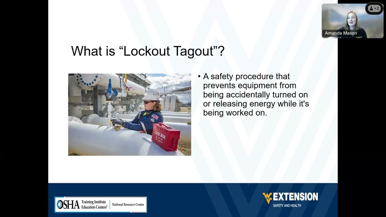
The US Department of Labor video below introduces lockout and tagout principles. It supports the planning discussion in this article. It is not a motor test demonstration, does not specify test values, and does not replace the site’s equipment-specific procedure.
Watch on YouTube — USDepartmentofLabor
Do not apply a motor insulation test indiscriminately through drive electronics. The qualified technician must establish the permitted test boundary using the exact equipment instructions.
No. Interpretation depends on the included circuit, method and conditions. A combined motor-and-cable result does not isolate the cause to one component.
No. Use the applicable equipment guidance, approved method and responsible technical review. Do not copy another installation’s pass threshold without establishing its relevance.
No. The result covers the defined test object and method. Reconnection, protective functions, operating behavior and any unresolved fault evidence require their own review.